A Butterfly Expansion Table
A hinged self-storing leaf hides under the tabletop until it's needed.
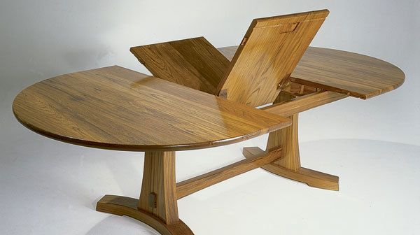
In a butterfly-leaf table, a hinged leaf stored under the top pivots up and unfolds to extend the table. This leaf-storage system eliminates the need to handle the heavy, bulky leaves normally used in an extension table and also avoids the possibility that forgotten leaves will be left behind in the excitement of loading up the moving van. Just this past year, I’ve had two jobs making matching table leaves to replace ones that had been lost. So when commissioned to design and build an extension table, I decided on the butterfly-leaf table for its practicality, aesthetics and absolute ease of operation.
The butterfly mechanism is not as complicated as it may appear, and once the basic geometry is understood, the mechanism can be built easily.
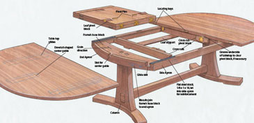
Fig. 1: Butterfly-leaf table construction. Click to enlarge.
The hinged-leaf sections counterbalance each other, as shown in the photo at the top of the page, and move almost effortlessly. The key to laying out the mechanics of the leaf is to build a full-scale mock-up based on the cross-sectional view of the butterfly leaf and aprons shown below in figure 2.
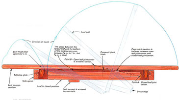
Fig. 2: Cross-sectional view of butterfly-leaf mechanism and aprons. Click to enlarge.
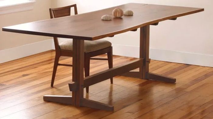
You must take into consideration that the leaves need space to swing freely under the table and that the aprons are an important structural part of the table. With the exception of these restrictions, there is considerable flexibly in designing a butterfly-leaf table. The top can be just about any size or shape and can be supported by a trestle base like the one shown in the photo at left or with a more traditional four-legged base. The table’s base-and-apron assembly are stationary, and the ends of the tabletop are screwed to glides that ride in grooves cut into the side aprons. For greater extension capabilities, the table could include multiple butterfly leaves.
In addition to the mechanics of the folding leaves, there are some other key areas that this article will touch on. The material from which the table is made will not only affect the appearance but also will have an impact on the function of the mechanism. For example, woods with excessive seasonal movement may interfere with the operation of the leaf. The hardware for the folding leaf is surprisingly simple, and much of it is easily shopmade, as are the guides and glides that the table ends slide on. And finally, I’ll discuss the pivot blocks, which ensure smooth operation and the locating keys, which position the leaf in relation to the tabletop. In the sidebar at the bottom of this article, I’ll described the simple templates I use to rout the mortises and tenons that connect the top to the base.
Making a mock-up of the butterfly mechanism
A full-scale drawing of the leaf in both the open and closed position and a working mock-up of the table-leaf mechanism are essential for planning and laying out a butterfly-leaf that opens easily, aligns properly with the tabletop and stores without interference below the top. To make the mock-up, draw a cross-sectional view, as shown in figure 2, on a smooth piece of plywood. Two thin strips of plywood, fastened together with a fabric hinge at one end, represent the hinged table leaf. Drive a nail through the mock leaf at the approximate pivot point, as shown in figure 2. Put another nail into the plywood drawing to represent the edge of the leaf support. Now you can move the mock leaf through its entire range of motion and experiment with the location of the pivot point and leaf support. As the top half of the leaf is lifted, the bottom half should ride on the leaf support and just barely clear the apron. To gain more clearance, you should move the aprons farther apart, but having the aprons as close to the folded leaf as possible provides the best balance and support for the open leaf.
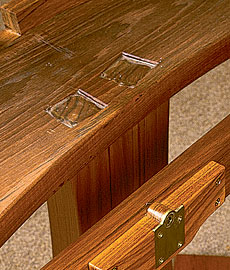
To make the mock leaf, rip two strips of 1/2-in.-thick plywood as wide as the tabletop is thick (1-1/4 in. for the tabletop shown in this article) A piece of fabric glued into the ends of the plywood strips simulates the action of the Soss hinges used in the actual leaf. The location of the folded leaf between the side aprons of the table is not critical, although I positioned my folded leaf so that it is centrally located between the aprons and parallel to the top. The space between the folded leaf and the underside of the tabletop must accommodate the pivot block without interfering with the top as it slides open and closed. As this space becomes larger, however, the side aprons must become wider to conceal the leaf below the table. About 5/8 in. clearance is ideal, but because I wanted narrow aprons, I left only 3/8 in. and consequently, had to groove the underside of the top to pass over the protruding cross-rail pivot blocks, as shown in the photo below.
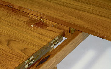
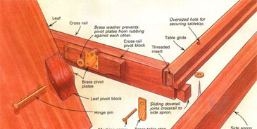
The butterfly-leaf mechanism includes cross-rail pivot block, the leaf pivot block and pin, and the Soss hinges that join the two halves on the leaf. The author grooved the underside of the tabletop to accommodate the pivot blocks’ knuckles, but this could be avoided by lowering the pivot point slightly.
Pivot-point placement is very critical and needs to be carefully laid out. After positioning the folded mock leaf on the drawing in the closed position, outline the leaf’s exact location on the plywood and remove the leaf mock-up. Then draw a line from the closed leaf-joint center (point A in figure 2) to open the leaf-joint center (point B, which must fall at the table’s center). The pivot point lies at the middle of this line.
Now, reposition the mock leaf on the drawing and glue a semi-circular block with a small hole drilled through it onto the leaf, so the hole aligns with the pivot point. A finishing nail, driven through the whole serves as the pivot point while a second nail driven into the plywood drawing simulates the contact point between the leaf and the edge of the leaf support. Clamp the plywood drawing in a vertical position so that the leaf hangs on the pivot nail and gravity holds the bottom half of the leaf against the leaf-support nail. Pull the top half of the leaf up, over and into the open position, while checking that the lower half of the leaf slides properly on the leaf support and clears the side apron by at least 1/4 in. Also, be sure the trestle or other substructure does not interfere with leaf movement. Although the leaf is balanced and moves with very little effort, it should not open on its own. If the leaf does not stay in the closed position, the pivot point needs to be moved toward the hinged edge of the leaf, which in turn necessitates repositioning the leaf and possibly the leaf support. It takes some experimenting, but once this mock-up functions properly, you are assured that the actual tabletop will operate flawlessly.
Choosing the right wood for the top and leaf
Most of the references I found on making butterfly-leaf tables recommend against using solid wood because seasonal movement or warping can cause the mechanism to bind or cause a mismatch between the leaf and the tabletop ends. My solid-wood table, now six years old, was built with wood movement in mind. Even though the table is subjected to humidity swings of 25 percent to 55 percent, it still works very well.
Wood selection is very important. I used teak for this table, but mahogany, oak or even pine will do, if it is high-quality, stabilized wood. The wood must be properly air- or kiln-dried (with no internal tension) and stabilized to the shop’s environment. Boards with a wild and undulating grain pattern or those that bind or warp when ripped are sure to have internal tension and should be avoided. The grain of the tabletop should run across its width, and to equalize or minimize warping, I recommend using the opposed-heart method when gluing the top as shown on the table’s edge in figure 1 above. To allow for seasonal movement of the leaf, I left 1/4 in. between the leaf and each pivot block. And because the aprons are the main structural support and form the glide system for the tabletop, quarter-sawn defect-free wood, with its grain oriented as shown in figure 2, is preferred.
Selecting and making the hardware
I joined the leaf halves with three heavy-duty Soss hinges (see sources of supply at the end of the article) that permit the halves to fold back on themselves yet are completely invisible when the leaf is open. The pivot pins that hold the leaf in the table are two ¼-in dia. by 3-1/2-in.-long solid-brass hinge pins. I had to scavenge them from a set of brass butts after I found out that I couldn’t just buy the pins. I might have been able to use the butt hinge leaves to make the pivot plates or table stops if I hadn’t already cut them from some 1/8-in.-thick by 1-1/2-in.-wide flat, brass bar stock. I also made a table lock from the brass stock. I cut the brass with a coarse metal-cutting blade mounted in a sabersaw and used drops of water as a cooling lubricant. I recommend wearing safety glasses to protect your eyes from flying brass chips. After roughing out, the brass is easily filed to shape, buffed to a bright shine with a felt buffing wheel and soft-metal rouge compound, and, finally, sprayed with Agateen 2-B cellulose-nitrate lacquer. Because these brass pieces are rarely handled, the lacquer provides a durable shine and prevents tarnishing.
To facilitate the removal and reinstallation of the tabletop, I screwed a threaded insert into the end of the tabletop glide, so the brass end stop could be fastened with an easily removed machine screw, as shown in figure 3 below. A hook-and-screw table lock, which holds the table ends together when the leaf is not in use, is mounted about 3 in. from the perimeter and across the joint on the underside of the table ends. When the table is fully extended, the weight of the leaf on the locating keys prevents the table ends from being accidentally pulled apart. But if you prefer, locks also could be installed on the leaf.
To strengthen the aprons against the leverage exerted by the extended tabletop, I reinforced the top ends of the side aprons with 1-in.-wide strips of 1/8-in.-thick by 10-in.-long flat, steel bar stock, as shown in figure 1. I screwed the steel to the side aprons with three #12 by 2-1/2-in.-long flat-head screws, positioned to avoid the slide groove on the aprons’ inside edges. The steel, located under the table ends, is not visible even when the table is fully extended on its glides.
Guides and glides
For each table end, there are two tabletop glides and one center guide, as shown in figure 1. The guides and glides should be made from a dense wood with the grain angling across the stock at 45° when viewed from the end (as shown in figure 2), which offers more lateral and shear strength. The end aprons and the cross rails are notched to allow passage of the tabletop glides, as shown in the top photo at right, and the end aprons are also notched for the center guides. The dovetail-shaped center guides provide additional support and prevent undue stress on the glides if the table is picked up by the top. The guides also prevent racking when the top sections are slid in and out and even can serve as stops if positioned to hit the cross rails when the top is fully closed.
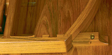
The table glide extends through the end apron, which is dovetailed to the side apron. Also shown are the dovetail joints that connect the frame’s base block and the cross rail to the side apron.
The guides and glides are screwed to the underside of the tabletop with round-head screws and flat washers through oversized holes. The oversized holes permit adjusting the glides and guides to their respective slots and allow for normal wood movement with seasonal changes in humidity.
Locating keys
Although locating keys and their corresponding mortises along the mating edges of the leaf and table ends, shown in figure 1, may be optional on other types of extension tables, they are necessary on a butterfly-leaf to secure the folding leaf in the open position. The locating keys also align the leaf with the table ends and when the leaf is folded, align the table ends to each other. I have found that three keys across the width of the table are sufficient. The key located near the leaf joint is positioned on the lower half of the leaf (when the leaf is closed), so it will clear the pivot block on the cross rails when opening or closing the leaf. The 1-in.-thick cross-rail pivot block automatically provides ample clearance between the locating keys (which should protrude about 5/8 in.) and the table’s ends. I’ve found that it’s best to wait until the leaf is ready to be installed in the table before cutting the mortises and setting the locating keys into the edges of the table ends and leaf. Then I can make last minute adjustments to be sure everything is perfectly aligned.
Mounting the pivot blocks
Because the leaf pivot blocks bear considerable weight and are subjected to some abuse as the leaf swings in and out of the table, I dovetail them into the leaf. Each of these joints is further reinforced with a brass pivot plate mortised into the side of the leaf, as shown in figure 3 below, and screwed to both the leaf and the block.
Fig. 3: Butterfly leaf mechanism. Click to enlarge.
Before installing the cross-rail pivot block, make sure that the table ends slide freely together and apart in a smooth, predicable fashion, and then mortise for and install the locating keys. To locate the cross-rail pivot blocks, clamp the tabletop ends and leaf together in the full extension position, and from under the table, screw the pivot blocks to the cross rails with a single screw. Gently swinging the leaf open and closed will reveal if any final adjustments are needed before securing the pivot blocks with three more screws.
| Trestle mortise-and-tenon templates
I connect the trestle base of my butterfly-leaf table to the upper assembly with a through wedged mortise-and-tenon joint, as shown in the photo below.
It’s a challenge to lay out and cut this joint exactly where I want it, with tenons that fit tightly into their mortises. However, the simple templates shown in the drawings below make lay out easy and ensure perfect-fitting joints every time.
Step one: Cut a piece of 1/4 in. thick Masonite to match the top of the trestle column. Cut the mortise openings; then scribe, cut and fit the tenon templates to the opening.
Step two: Position the mortise template on the column end, drop the tenon templates into place, and after predrilling the Masonite, nail the tenon templates onto the column with brads. Remove the mortise template.
Step three: Rout away the waste, taking about 1/16 in. per pass with a flush-trimming bit with the bearing mounted above the cutter. Be careful not to contact the template until you’ve cut deep enough for the bearing to ride along the template.
Step four: Position the mortise template on the frame’s base block and rout away waste in the center of the mortises. Again, keep the router bit away from the template until the bearing will ride on it. Square up the mortise corners with a chisel. |
Sources of Supply
- Soss hinges and threaded brass inserts are available from Woodcraft Supply.
- Brass bar stock for making pivot plates, stops and table locks is available from Industrial Metal Supply Co.
- Agateen 2-B lacquer for coating brass is available from Agate Lacquer Manufacturing Co.
Drawings: Bob LaPointe, Photos: Sandor Nagyszalanczy and Paul Schürch
From Fine Woodworking #94
Fine Woodworking Recommended Products
Stanley Powerlock 16-ft. tape measure
Dividers
Dubuque Clamp Works Bar Clamps - 4 pack



Comments
Just about the nicest dining table that I've seen and it would be a great challenge to make. It's a shame that the drawings are not dimensioned, to at least give an idea of the size, and of course, the leg details would be great, too.
Yes, I would very much like some more details about this build. I also wish I could download the article as a PDF so it would be easier to read and study the drawings.
Log in or create an account to post a comment.
Sign up Log in