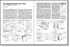
Synopsis: Ian J. Kirby continues his series on the mortise-and-tenon joint. In this article, he talks about designing mortise-and-tenon joints and how to stop the joint below the top surface of a table or chair. Using these sloping or square haunched mortises and tenons improves strength, he adds. Illustrations show the form of the joints and suitable proportions. He explains the steps necessary to cut the mortise and tenon and how to avoid common errors.
The most basic of woodworking problems is joining two pieces of wood together at right angles to form a corner. The most common joint for doing this is the mortise and tenon. We are usually in one of two situations: first, where two pieces of similar thickness are being joined, as in the corner of a door frame (fig. 1); and second, where a third piece of wood of dissimilar thickness is involved, as in a typical table or chair joint between apron and leg (fig. 2).
When designing these joints, note that the top edge of the mortised member—the vertical piece in the illustrations— will be in line with the top edge of the tenoned rail. If you want the final appearance to be as shown, then the joint must be stopped somewhere below the top surface. The usual solution is to add a haunch, which may be either square or sloping. Both variations strengthen the joint and increase the gluing area, and the basis for choice is visual. If you want a clean, uninterrupted line at the top shoulder of the joint, you would use the sloping haunch. If you don’t mind the interrupted line or if the joint will be concealed, the square haunch is a little easier to make and a little stronger.
The illustrations show the form of the joints, and the elevations suggest suitable proportions. I must emphasize here that it is the responsibility of the designer to detail all the joint dimensions to achieve the visual effect he wants as well as the mechanical strength the structure requires.
The main reason for the haunch is strength. Resistance to twist is especially improved. If you leave the haunch off altogether (fig. 3), the result is that about a third of the width of the rail is free-floating, with no mechanical bond and no glue bond where it needs it the most. If you go to the other extreme and make a bridle joint, you sacrifice mechanical resistance to downward loading. Although glue is strong in shear and the joint has a great deal of gluing area, the two parts meet at right angles. This puts considerable strain on the glue line when the wood shrinks and expands, and the condition is aggravated by the large amount of exposed end grain.
From Fine Woodworking #18
For the full article, download the PDF below:
Fine Woodworking Recommended Products
Veritas Standard Wheel Marking Gauge
Veritas Precision Square
Festool DF 500 Q-Set Domino Joiner




Log in or create an account to post a comment.
Sign up Log in