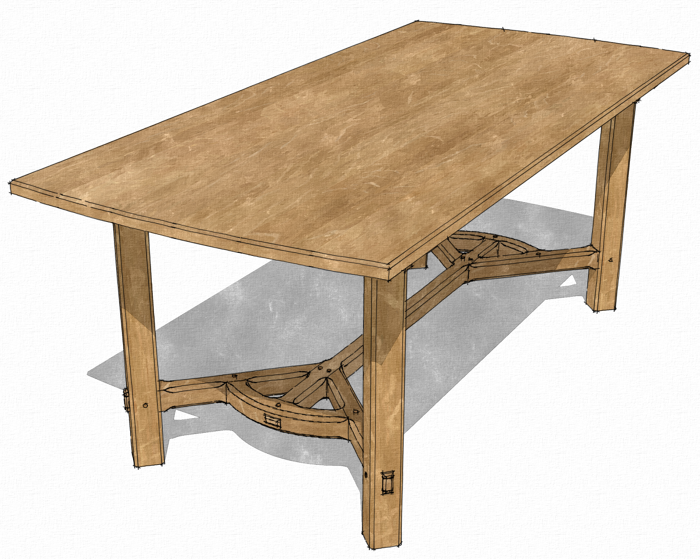
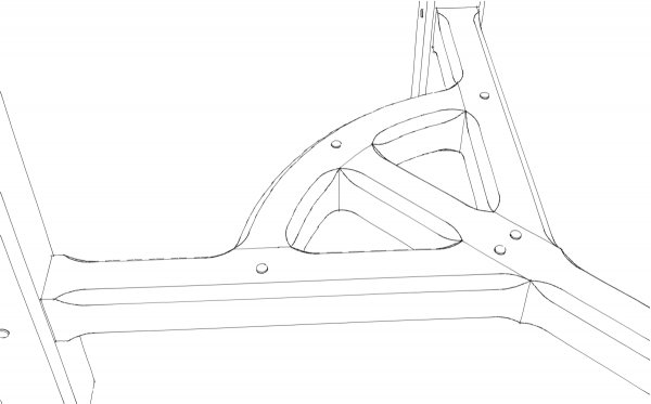
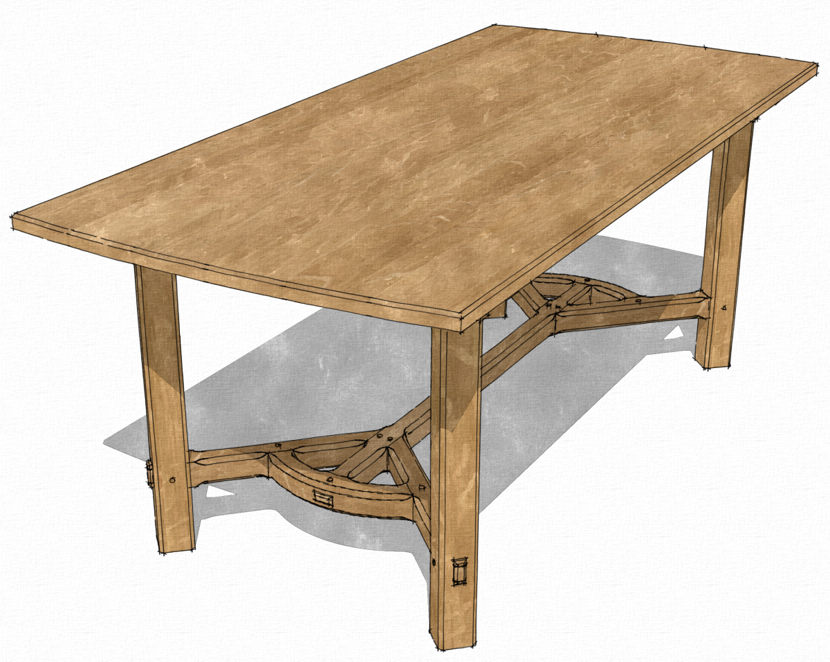
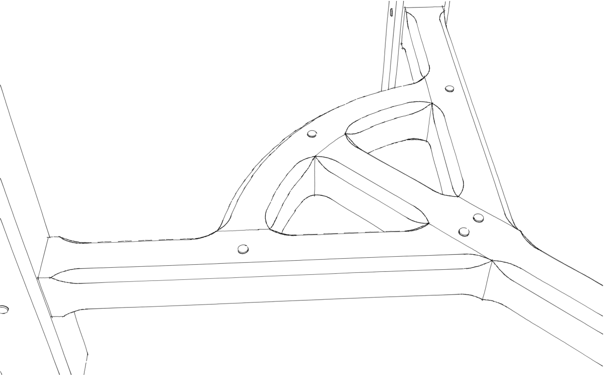
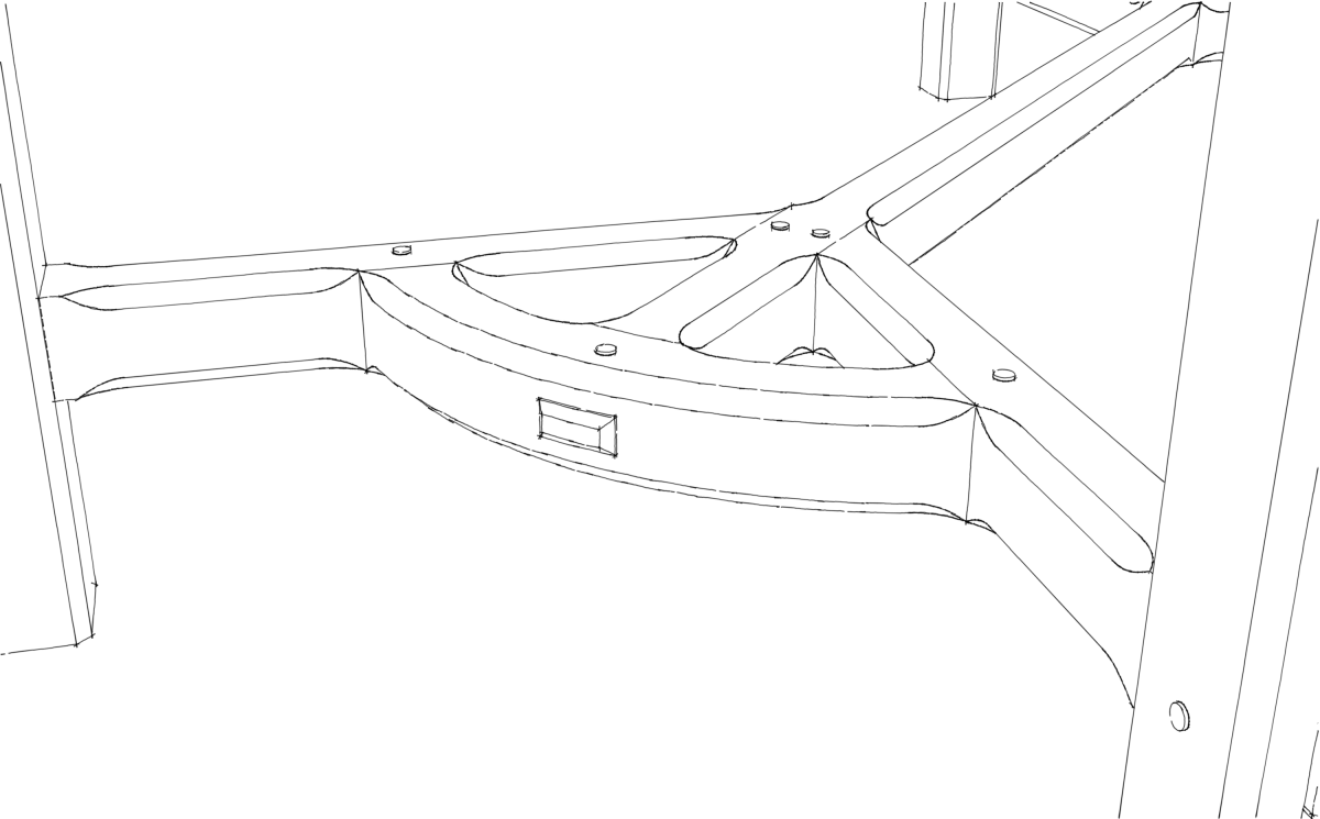
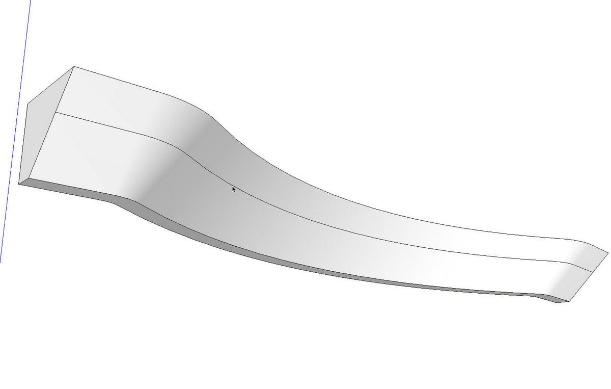
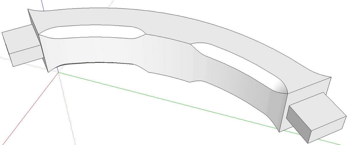
When I was working on the SketchUp model for the plans to Michael Peckovich’s Arts and Crafts Dining Table, I had to draw the chamfers on the curved end caps of the hayrake stretcher. The curves on these end caps are simple arcs and adding unstopped chamfers would be a very simple Follow Me operation. In this case, though, they are stopped. The process to create them takes a little additional set up but it really isn’t that much different from the unstopped version. Here’s how I did it.
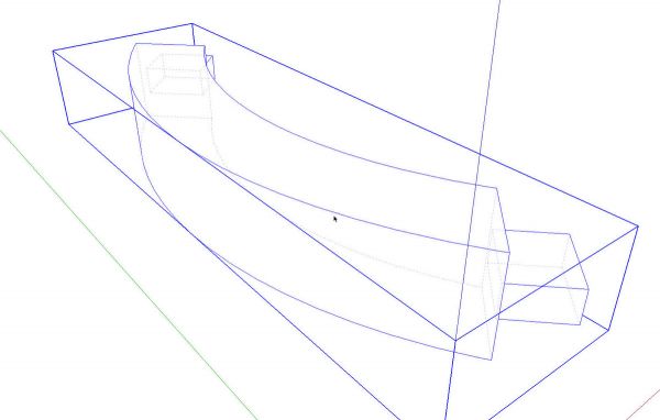
In SketchUp I always start by drawing the parts without details such as chamfers, roundovers, joinery and so on. I make components of each parts as I work. I get all the parts drawn and then go back and add the details. As I’ve demonstrated before, this is very efficent for me because often the details on one component require referencing the neighboring parts. This is especially evident when drawing joinery.
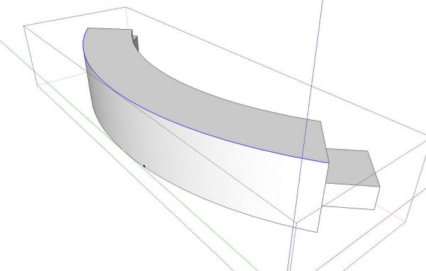
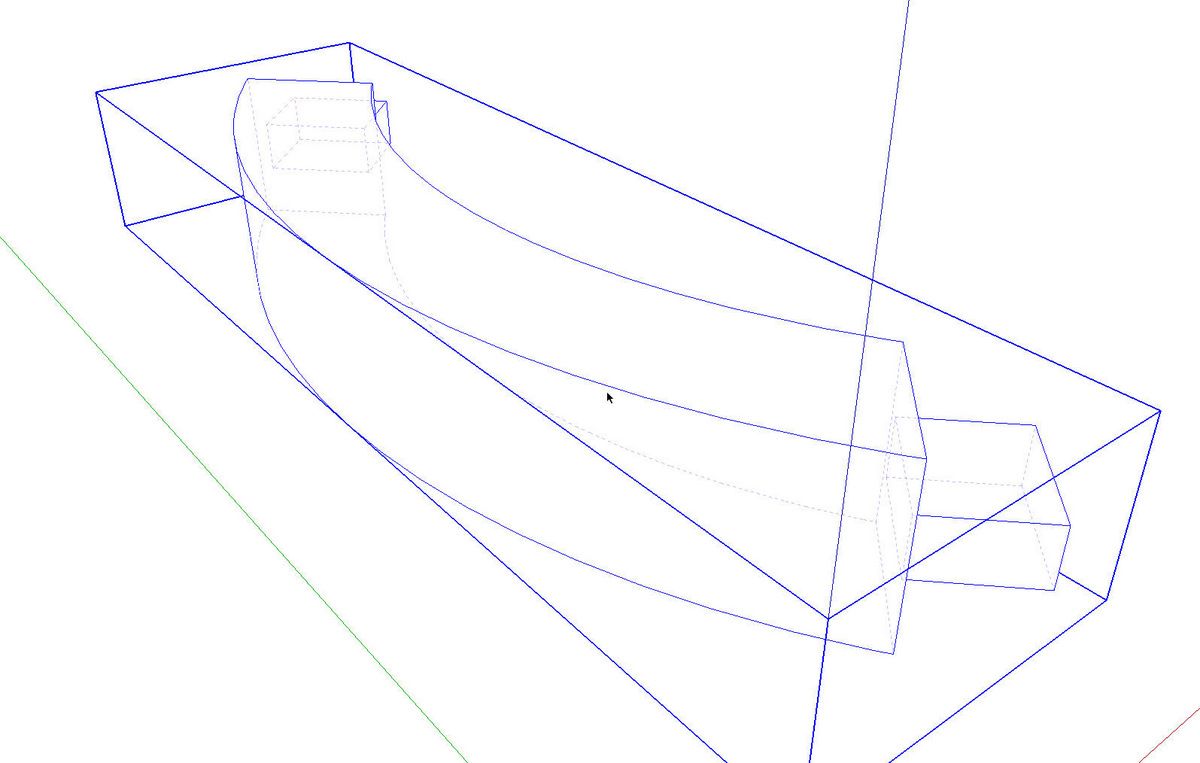
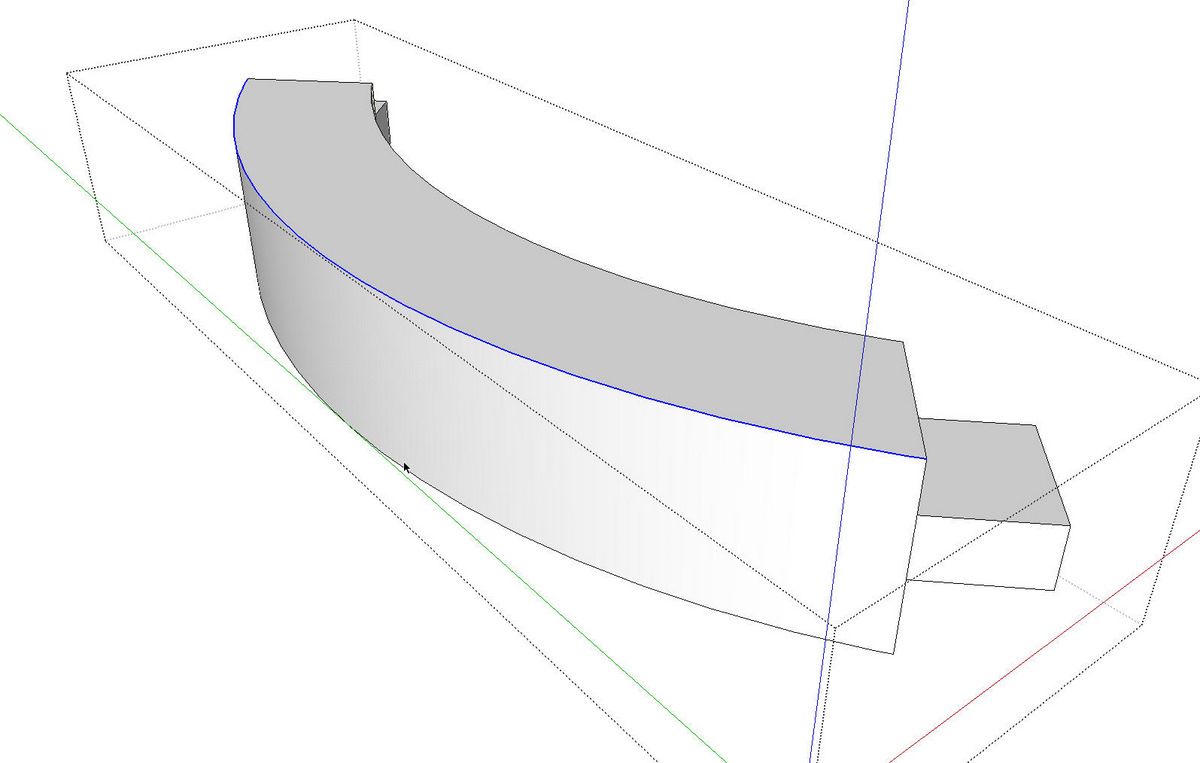
I’ll be using Follow Me to create the chamfer and for that, I need a path along which I can extrude a profile of the chamfer. I tend to think of these sorts of things in terms of how they would be done in the shop. These chamfers are to be cut with a router so I’ll draw the shape of the space through which the router bit would pass. Iopened the cap component for editing and selected the outer edge of the top surface.
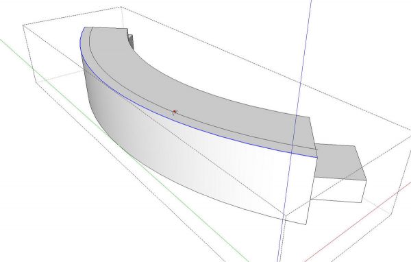
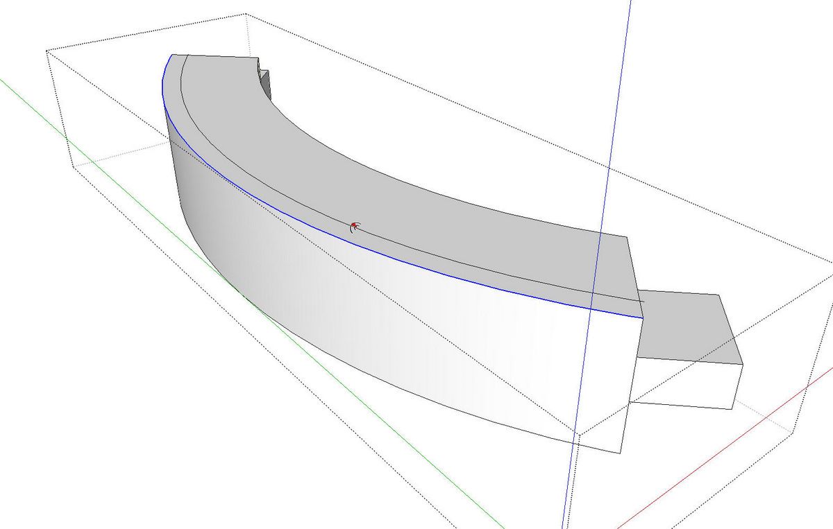
I got the Offset tool and offset arc 3/8 in. because the chamfer was specified to be 3/8 in. by 3/8 in.
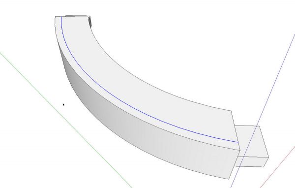
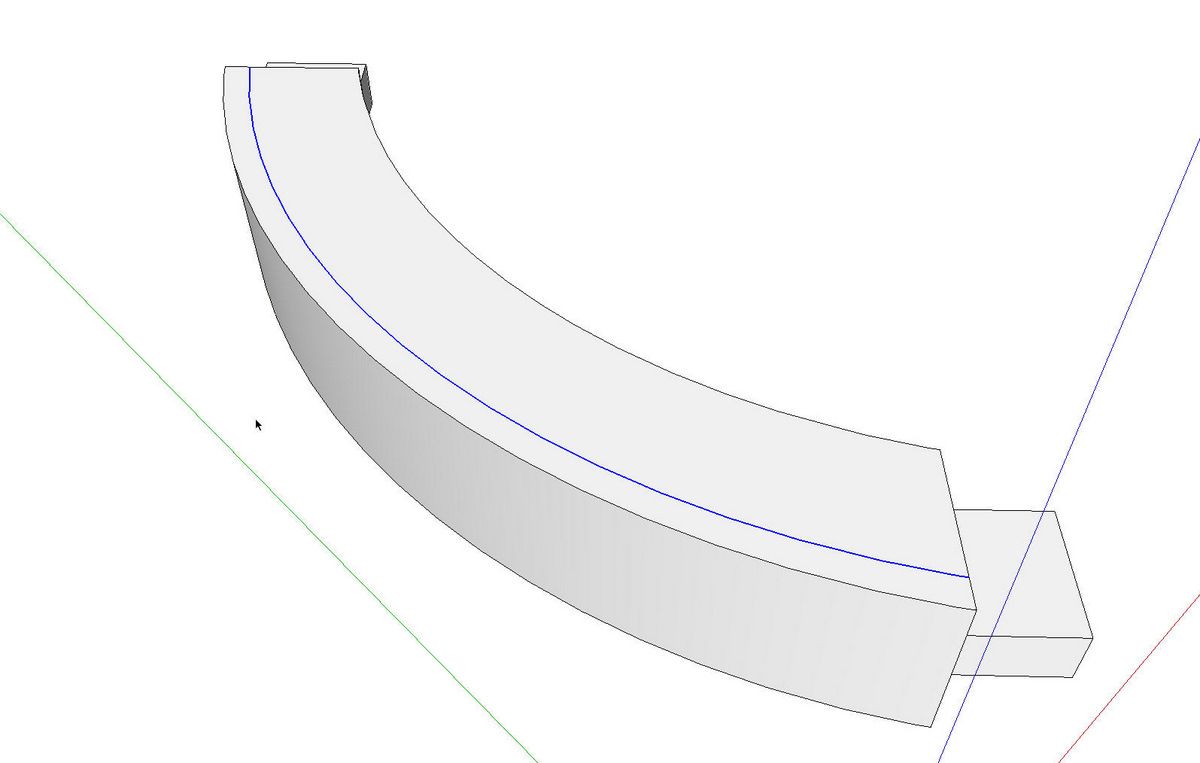
I then Cut (Scissor tool, Edit>Cut, etc.) the offset arc, closed the component for editing and hit Edit>Paste in Place.
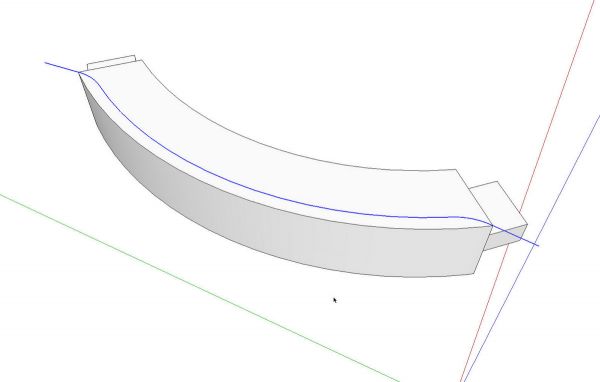
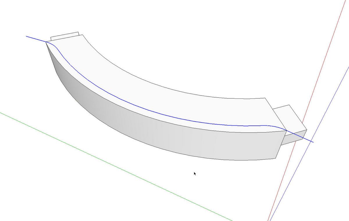
Then I drew some small arcs from the offset arc to the corners of the cap. Then I added some short line segments off the ends of those small arcs. The length of these lines isn’t very important but You want to make sure that they are long enough so that the ends of the extruded profile clear the cap. I drew these lines so that they are colinear with the end segments of the small arcs. With the path created, select all of it and use Weld to weld it into a polyline.
My anaolgy for these lines at the ends is the router. You would start the router bit spining before it contacts the work and you would move the router away from the work before shutting the motor off.
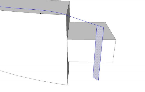
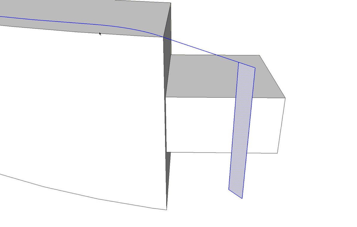
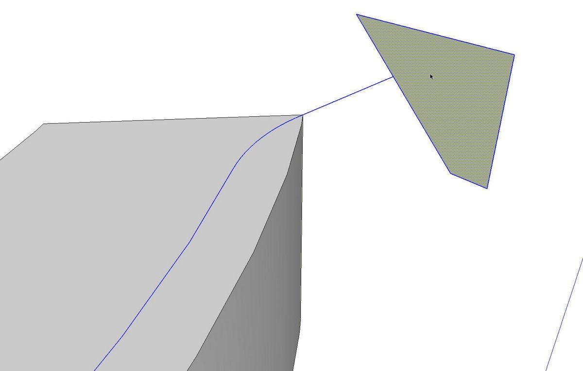
In order for Follow Me to work as expected, the profile needs to be perpendicular to the first segment of the path. Here’s a simple way to create a perpendicular face on which to construct the profile. Draw two vertical lines down from the end of the path. Connect the two lines to create a face.
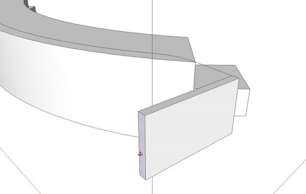
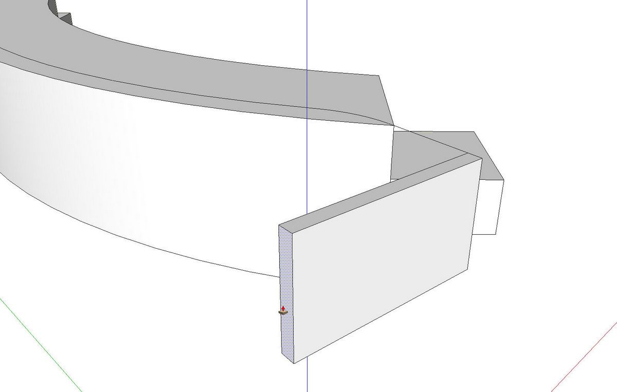
Use Push/Pull to extrude that face.
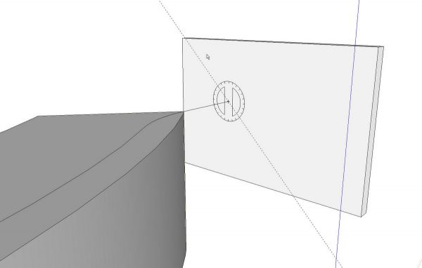
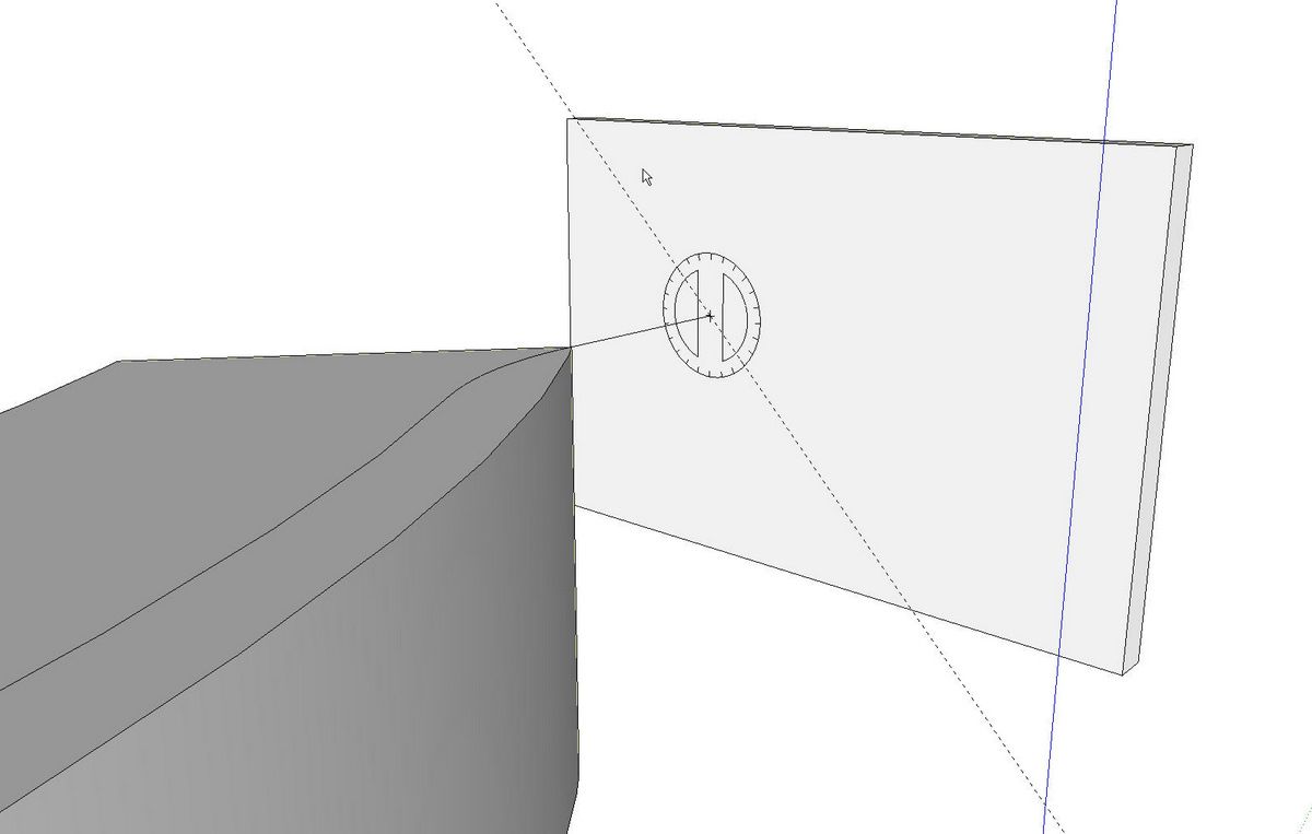
Use Push/Pull to pull the box up in the vertical direction and to the opposite side of the path. Then use the yellow Protractor tool to put a guideline on the face at 45°. Trace that guideline with the Line tool and delete the unneeded parts leaving just the profile of the cutter.
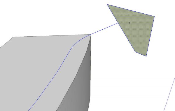
Now were ready to run Follow Me on the profile. I like to select the path, get the Foolow Me tool and click on the profile. After Follow Me has run, orbit around to check that the extrusion runs off both ends of the cap correctly. Then I make the extrusion into a component. That saves it into the In Model component library so if I need it again, I don’t have to remake it.
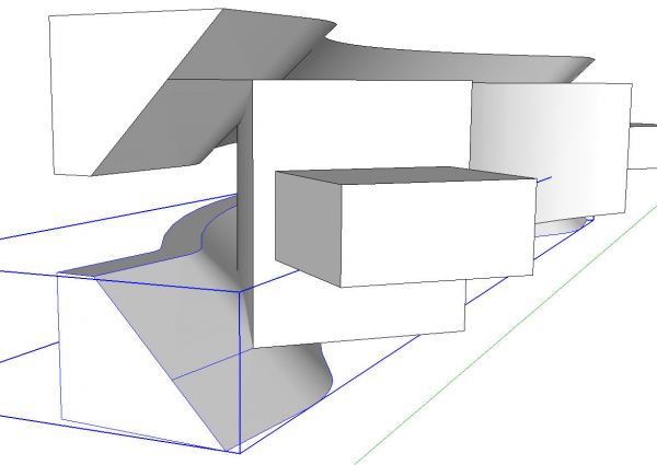
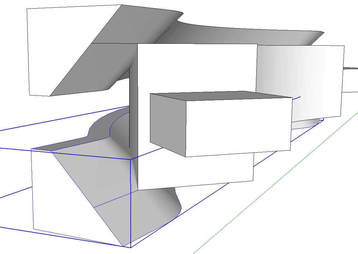
Since this cap gets the same chamfer on the bottom, I copied (Move+Ctrl) the chamfer component, flipped it along the blue axis and placed it correctly on at the bottom of the cap. You can see in the image above, the line from the Follow Me path is included in the component. I used that line with the Move tool to locate the chamfer component in the right place.
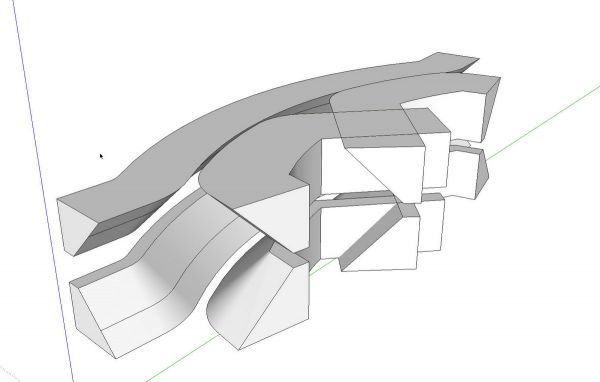
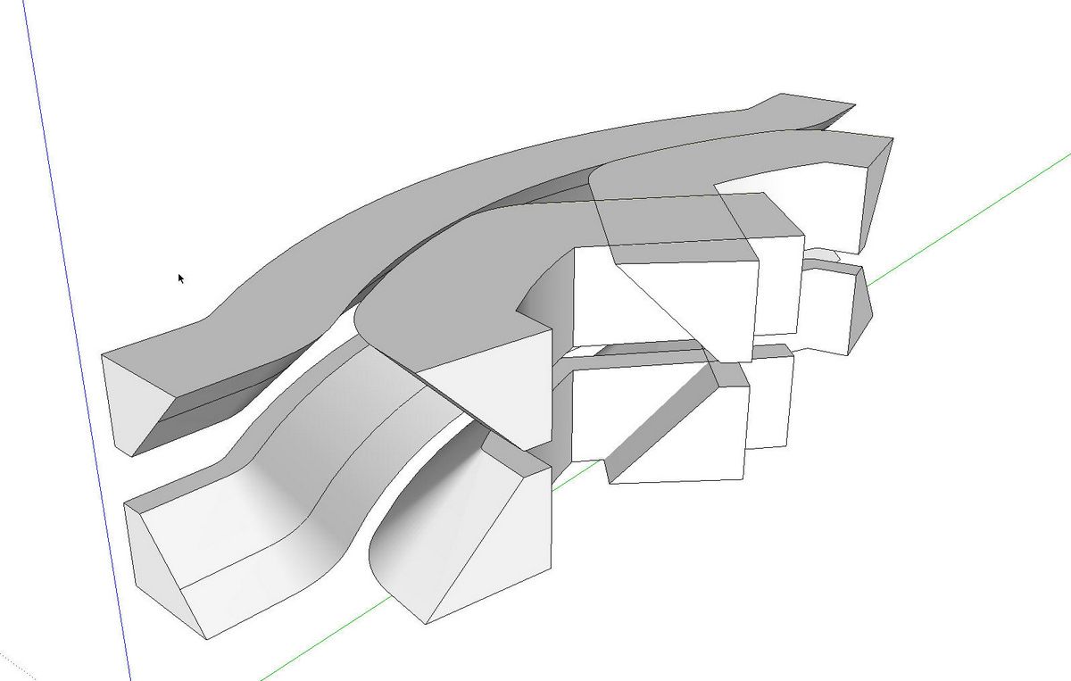
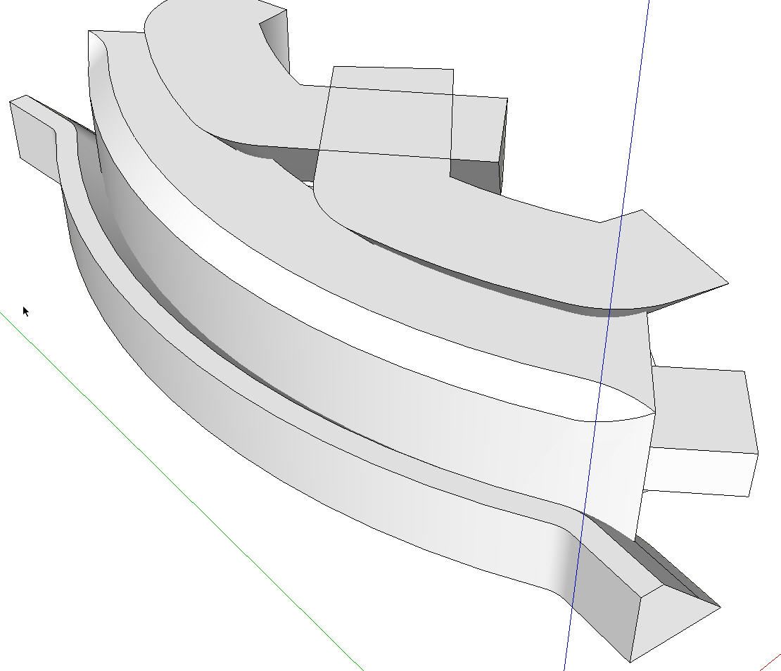
I repeated this process for the inner chamfers. I only needed to draw one of them and then I copied and flipped the component to make the other three. I’ve hidden the cap in the image above so you can see just the cutters.
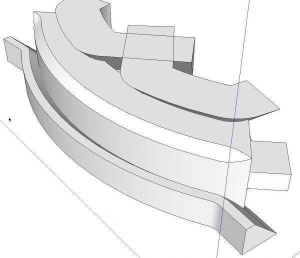
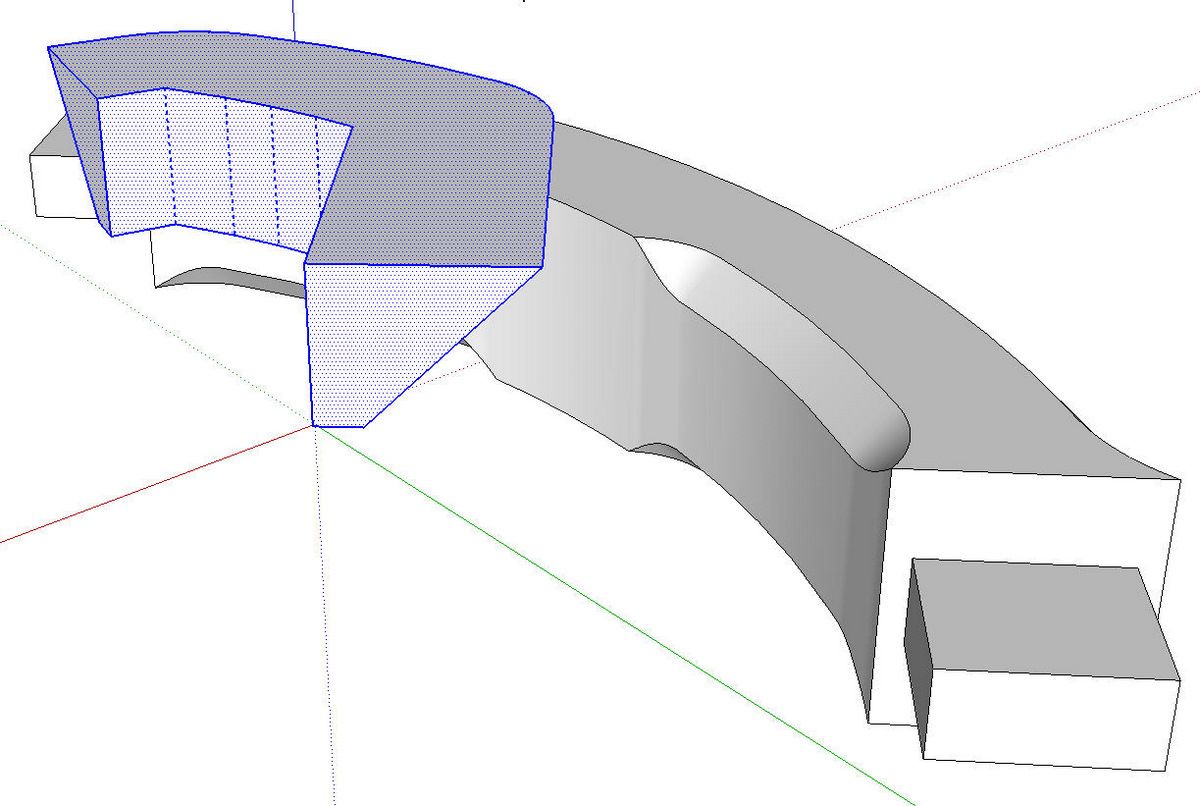
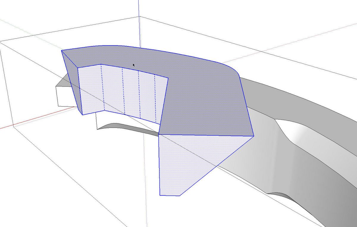
With the pro version of SketchUp 8, the Subtract tool makes quick work of chamfering the cap. Without the Subtract tool, though, you’ll use Intersect and then the Eraser tool to delete the waste.
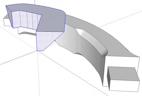
Explode the chamfer components.
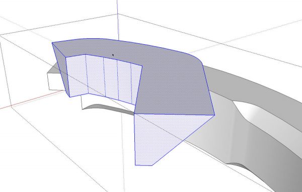
Select all the geometry and Cut it (Edit>Cut, Scissor tool, etc.), open the cap component for editing and use Edit>Paste in Place.
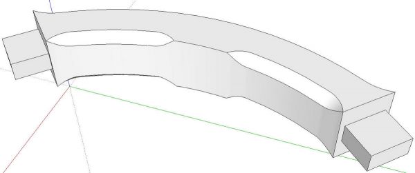
Select all of the geometry in the component, right click on it and choose Intersect Faces>With Selection. Delete the waste and correct the face orientation as needed.
You’ll notice I made components of all the parts involved here before exploding and intersecting. I could have created all of the chamfers inside the cap component but from experience, I’ve found it is safer to make these things as separate entities because it avoids potentially unwanted modifications to the component. The cap component won’t be modified until I’m ready to do it.



Comments
Great post Dave, very clear as ever. Looks familiar to a problem I was grappling with a while ago. Thanks.
Very interesting post Dave, as always!
Another great post Dave Thanks again
Slick trick, Dave! Nice, clear presentation of the process. Now I won't struggle to produce "routed" corner profiles any more.
Matt
aka The Timber Tailor
Log in or create an account to post a comment.
Sign up Log in