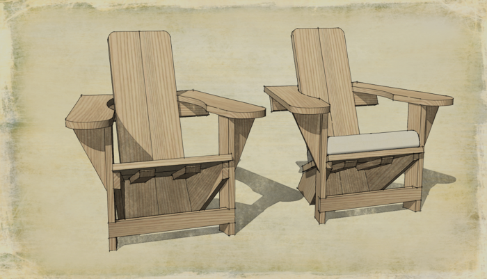
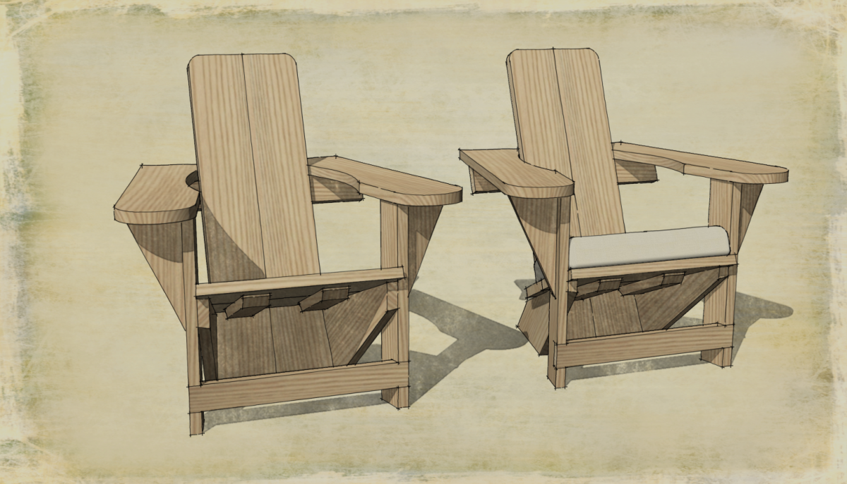
Recently, during one of my online tutoriing sessions, my student and I were talking about the components in a corner cabinet model he was working on. He had drawn the components in situ as Tim and I advocate. He discovered some unexpected things in his model, though. These same things occurred in the model of a Westport chair I drew this morning.
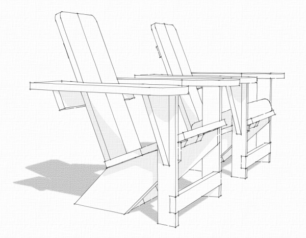
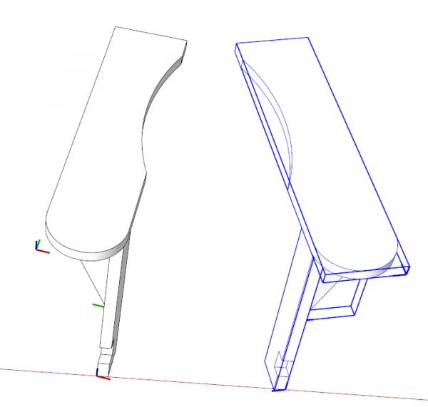
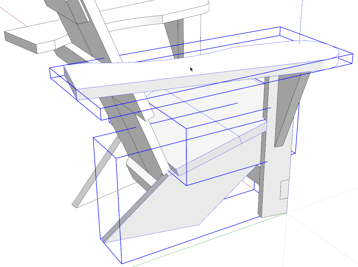
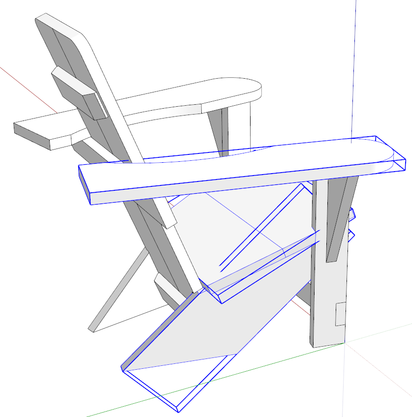
I drew all the parts in place as normal starting on the left side and working toward the right. When I made the components their bounding boxes were created with the edges parallel to the model axes. You can see this in the next image.
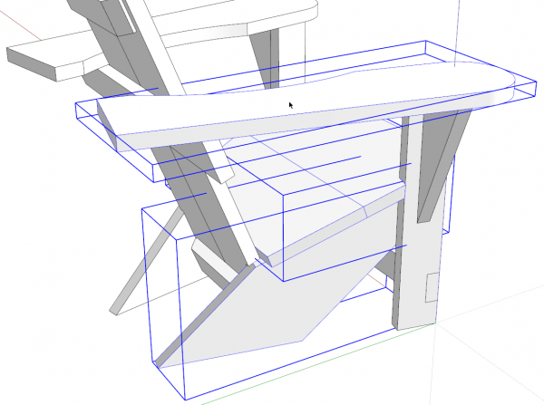
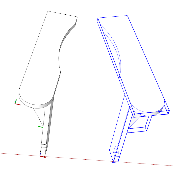
This is normal but can create some issues later on. One of those issues shows up when applying materials because they go in aligned to the component’s axes so they typically need adjustment to align correctly. Another issue rears its ugly head if you choose to make a cut list from the model. The cut list plugin reads the dimensions of the bounding box. In the model as shown, above, this would result in errors and an amzing number of board feet required to build the project. You can imagine how much waste there’d be if you cut this chair’s back leg from a block of wood as large as that bounding box.
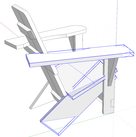
So the fix is to adjust each component’s axes so the bounding box fits tightly as in the image, above. I’ve written several times about changing component axes. See here for example. But deciding when to change those axes can be important. If you do it to early in the modeling process, it can create extra work. It might seem that adjusting the component’s axes orientation right away would make sense but for something like this chair, maybe it’s not a good idea.
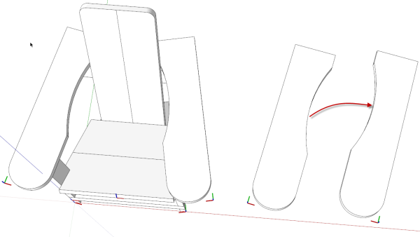
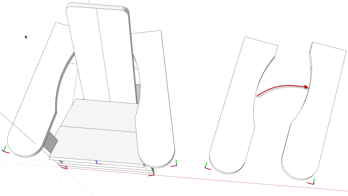
For example I drew the left arm rest and copied it to make the right side. The usual thing to do with the right side would be to mirror it using Flip Along. In the image above the flip direction would be along the component’s red axis. It creates a mirror image alright but the angle is wrong as you can see on the right. the next step would be to rotate the right side armrest to the correct angle.
When I drew the chair on the left, I copied and flipped the arm rest before changing the component axes so I didn’t have to take the extra rotate step. The angle was correct by default.
When you flip a single component the flip along directions are based on that component’s axes directions. When you choose Flip Along from the context menu you’ll see the options are “Along Component’s Red”, “Along Component’s Green”, and Along Component’s Blue.” However, if you select more than one component and flip them, the flip direction is based on the model or global axes. You’ll see the Flip Along options are now “Red Direction”, Green Direction”, “Blue Direction.”
You can leverage this behavior if you think ahead a few steps. Once in awhile I’ll run into a situation where I need to mirror a component but flipping it would also require rotation or other gymnastics to place it correctly. Rather than go through all that, I just select another component with it and flip the two of them. If I don’t need the extra component I simply delete it after the flip.
Many times it doesn’t matter what order you do things in sketchUp. Sometimes, though, choosing the right time to do them can make a difference in how much work you have to do later. Try to think a few steps ahead as you are modeling to find ways you can improve your efficiency.



Comments
Great tip about flipping multiple components! That will come in very handy.
Thanks, Dave
Log in or create an account to post a comment.
Sign up Log in