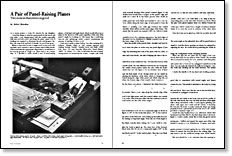
A Pair of Panel-Raising Planes
Two is more than twice as good
Synopsis: Robert Bourdeau made himself a pair of planes, a left-hand plane and a right-hand plane, that allow him to plane in the direction of the grain no matter which side of the panel he might be working on. They work better than a shaper and were cheaper than custom-ground shaper knives. Here he cites the research he did to find out how to make the planes and the project planning that determined the plane’s profile, field, shoulder, and bevel. He explains how he decided to set the iron’s skew and how he ground the cutter and the scribing spur. Multiple photos and drawings illustrate the plane construction.
From Fine Woodworking #30
In a recent project, a Louis XV armoire for my daughter, I used the shaper to raise the many panels for the doors and case sides. I was disappointed with the results—especially with tear-out both across and along the grain. Quite a bit of sanding was required to eliminate the pits and gouges; further, the crisp look and feel of cleanly cut wood was gone.
When it came time for me to begin work on my son’s rolltop desk, and I wanted to raise its panels with double bevels, I discovered that the appropriate shaper knives would have to be custom-ground at a high cost. There had to be a better way, so I decided to make myself a pair of panel-raising planes, a left-hand and right-hand, which would allow me to plane in the direction of the grain regardless of the side of the panel I might be working on. This meant that I could keep tear-out and splintering under control, minimizing the amount of sanding I’d have to do.
I had never made a plane before, but after studying K.D. Roberts’ Wooden Planes in 19th Century America and reading Norman Vandal’s “Paneled Doors and Walls” (FWW #18, Sept. ’79) and Timothy Ellsworth’s “Hand Planes” (FWW #1, Winter ’75), I felt I could make the pair of panel-raising planes by laminating the bodies. I began with a full scale sectional drawing of the panel I wanted (figure 1); the double bevel would form a tongue on the panel’s edge and make for a nicer fit in the frame grooves than would an unrelieved wedge. Using 3/4-in. stock, I divided the thickness of the panel into even thirds and decided to cut a 1/4-in. by 3/8-in. rabbet along the back edge of each panel to form the backside of the 1/4-in. tongue. When captured in the grooves, there’s a resulting 1/8-in. wide gap between the vertical shoulder of this rabbet and the inner edges of the frame. This means that the panel can expand a full 1/4-in. before it exerts any pressure against the frame, a sufficient allowance for most panels, unless they are exceptionally wide or made from an unstable wood. For a pleasing appearance, the back edges of the panel can be chamfered or slightly rounded over, as can the inner edges of the frame.
Since the profile of the panel’s field, shoulder and bevel is the exact complement of the plane’s sole, it was an easy matter to draw the plane in section atop the panel (figure 2) just as though the plane were making its final pass down the edge. By laminating the body of the plane with two sides, or cheeks, and a three-part core (a front block, an adjustable shoe and a rear block), the task of shaping the sole to the required angles was made much easier and simpler than would have been the case had I tried to make the entire body from a solid block in the traditional way.
For the full article, download the PDF below:
Fine Woodworking Recommended Products

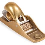
Lie-Nielsen No. 102 Low Angle Block Plane

Stanley Powerlock 16-ft. tape measure

Marking knife: Hock Double-Bevel Violin Knife, 3/4 in.


Log in or create an account to post a comment.
Sign up Log in