I suppose I am only one of many readers of Fine Woodworking intrigued by an early article about wooden-works clocks (FWW #10). My first efforts were only nominally successful (in large measure because I can be impatient–I wanted to build the whole clockworks and sit back and watch it run). Well, it ran, but it had so much internal friction that it required 12 lb. of drive weight. Beyond that, its tick-rock was not as consistent as even a novice clockmaker would like. Although it won a best-in-show in one woodworking exhibition, it did not satisfy me. In fact, a couple tried to buy it at a show in Philadelphia, but luckily–for them as well as for my reputation–I was able to persuade them to wait a few weeks for the improved model.
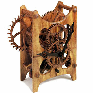
 Clock construction is a study in perseverance, patience and forethought. Dad charges, “Boy, you ‘re in too much of a hurry. You’ve never got enough time to do a job right the first time, but you’ve always got time to do it over.” Like most fathers, mine proves to be right with uncanny, and sometimes irritating, frequency. Nevertheless, I have to wonder if “doing it right the first time” is even possible with clocks-mine seem to work better with each one I build. The grandfather clock described in this article runs two days on a winding and carries two 3-lb. drive weights. It is accurate to about a half-minute per day.
One of my latest clocks, which I call the Oval, ran in the workshop on an astonishing 1 3/4 lb. of weight. I am hoping to get my next generation of grandfather clocks to run five or six days on 6 lb. of weight. This kind of performance requires great precision. Are setups and measurements with a machinists’ dial caliper going too far? Perhaps, I can’t say for sure–I only know I feel better for doing the best I know how. Doing less would reduce the pleasure of the craft and result in something other than the heirloom timepieces I intend my work to become.
What is a clock?–In the strict definition, a clock is a timepiece that signals the hours by striking a bell. But in broader terms a clock is a mechanical device designed to release stored energy in small, equal increments over a period of time.
The energy in purely mechanical clocks is typically stored in one of two ways, either in a coiled spring or in a falling weight or weights. In a spring-driven clock, a fully-wound mainspring delivers maximum drive energy, but this force decreases constantly as the clock runs down. Spring-driven clocks, therefore, require special compensating mechanisms that are beyond the scope of this article.
The most practical power source for mechanical clocks is the energy provided by a falling weight, which remains constant for the duration of the weight fall. It is a simple matter to compensate for the internal friction of the clock movement by increasing the drive weight. Of course, too much weight will accelerate wear, deform bearings and possibly even bend the weight arbor.
As shown in the drawing on p. 33, the weights in my clock are wound around a drum 1 in. in diameter, which acts as a lever–the larger it is, the more force it will transmit, but the faster the weights will fall and the sooner the clock will have to be rewound. The less internal friction in a clock (and the more efficient it is in general), the smaller the drum can be, and the longer the clock will run with any given weight.
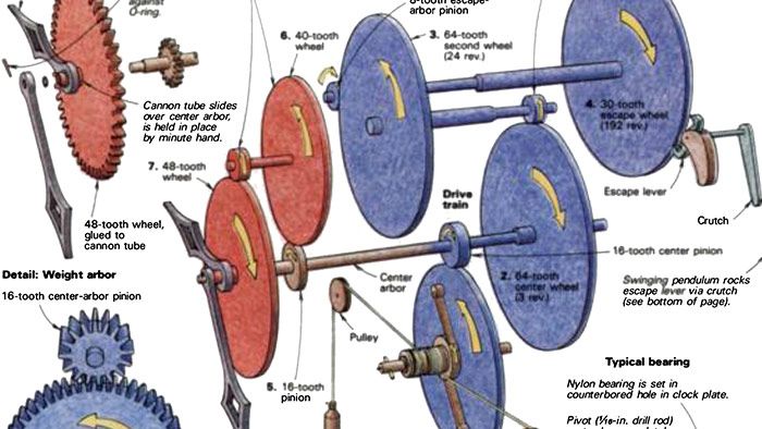
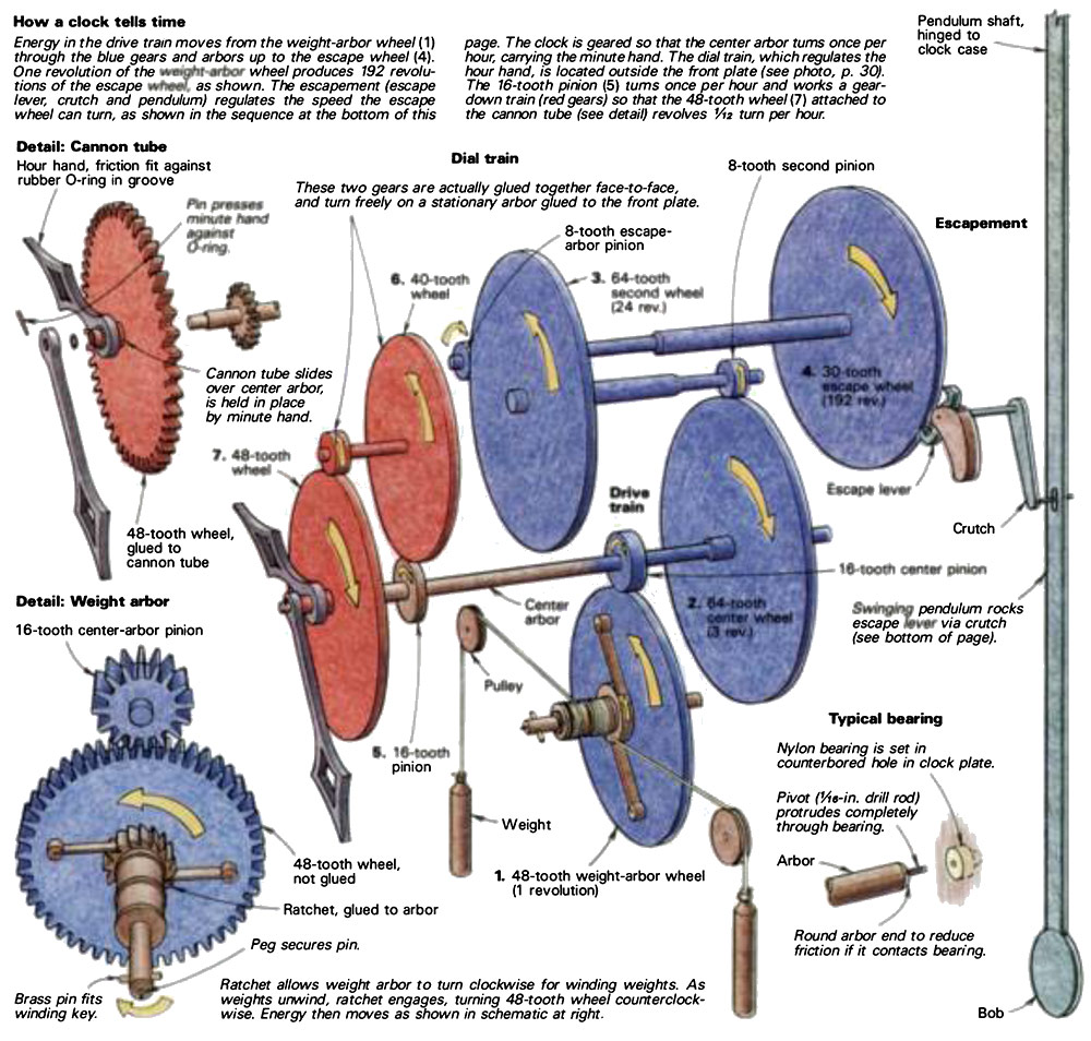
Converting weight into time–At first glance, a clock seems a confusingly complex mechanism, but a few minutes’ study will prove that a basic timepiece such as this one is surprisingly straightforward. The clock turns energy into time by means of two gear trains, a drive train (or going train) and a dial train, which moves the hands. An escapement mechanism controls the rate at which the energy stored in the weights is released. The escapement mechanism consists of an escape wheel, an escape lever, a pendulum and a crutch.
The weights connect to a weight arbor at the beginning of the drive train, and from there a series of gears increases the speed at which each successive arbor turns (the arbor is the shaft the gears are mounted on). This sort of gear-up drive, where large wheels are driving smaller pinions, is unique to horologic al applications. In most other gear trains, pinions (the small gears) turn wheels (the large gears) in order to convert the fast, lowpower revolutions of a motor shaft to an output shaft that turns slower but has more torque. Because the drive train of a clock is a gear-up train, the tooth profiles on its wheels and pinions are not the same as those in most other gear trains, a consideration discussed in the box on p. 34.
The speed of the drive train triples from the 48-tooth wheel on the weight arbor to the first pinion, then increases by eight, then by eight again. The result is that the escape wheel wants to turn 192 times faster than the weight-arbor wheel. Ignoring all internal friction for the moment, this means that the clock’s 6 lb. of weight (or 96 ounces) can be stopped by 1/2-ounce force applied to the pinion on the escape-wheel arbor.
If we apply the force to the escape wheel itself, which is much larger than the pinion, the stopping force decreases to about 1/16 ounce. And when we introduce the power losses due to the clock’s internal friction, which occurs not only at the bearings but also between the pairs of teeth as they engage and disengage, we see that it takes very little force to prevent the escape wheel from turning.
Thus the escape wheel is a good place in the drive train to regulate the rate of release of the energy stored in the clock’s weights–because little force is involved, the acting parts can be light in weight and, further, they will be subjected to little wear.
The escapement mechanism–The drawing above traces the path of the drive force of a clock by starting at the weights. But in designing a clock, the escapement is where you would start, because all clocks depend on the following interrelationship: the internal gearing determines the length of the pendulum; the length of the pendulum suggests the internal gearing. For those interested, I’ve included a mathematical discussion of gear ratios and pendulum lengths (at right).
The pendulum regulator developed around 1675. It superseded the verge escapement, the earliest escapement known, which dates from the 13th century. Verge escapements required a large oscillation of about 100° of arc and were, therefore, not very accurate. With the development of the recoil escapement, the pendulum oscillation was reduced to between 5° and 10° of arc. Within this range, the period of a pendulum (the length of time it takes to swing from right to left or from left to right) is constant, or nearly so. It is this principle upon which all pendulum regulators are built.
The exact period of a pendulum can be calculated mathematically, at least in theory. In the real world, theory and actuality do not quite correspond, but it remains true that to lengthen a pendulum’s period, you lengthen the pendulum; to shorten the period, you shorten the pendulum. In my grandfather clock, the bob–the weight on the end of the pendulum shaft–is adjustable up and down. By moving the bob, the pendulum can be adjusted to swing faster or slower, thus speeding or slowing the clock.
With each oscillation of the pendulum, one tooth of the escape wheel is released and the entire gear train of the clock is allowed to advance proportionally. More specifically, the escape wheel and escape lever constitute the release/relock mechanism. As shown in the drawings below, the pendulum, working through the crutch, rocks the escape-lever arbor back and forth, so that the escape lever will stop and release each tooth on the escape wheel according to how fast the pendulum is adjusted to swing. It is important to keep in mind that though the pendulum controls the movement of the crutch and, therefore, of the escape lever, it would stop without the impulse it receives from the escape wheel and the escape lever through the crutch. This push is essential, because it is the force that keep s the pendulum swinging. There are at least a dozen major clock escapements, all designed to solve one problem or another, but only two–the recoil and the dead beat- seemed practical for me to construct in wood. The recoil (the escapement analyzed in FWW #10) is so named because there is a small counter-rotational movement of the escape wheel for each swing of the pendulum.
The dead beat escapement, a significant refinement, was invented by George Graham about 1730. In a weight driven clock with a long pendulum, it is probably the best escapement to use. It gives a steady, constant beat–and with no recoil, the drive train moves in only one direction. My version of the dead beat uses a “club foot” escape wheel–it is a bit more difficult to construct than the standard recoil, but it offers larger wear sufaces that should allow a wooden mechanism a long life.
The dial train–With this much accomplished, we have a mechanism that will keep time, in the sense that the pendulum will swing at a steady rate until the weights have fully unwound. It remains for us to translate the mechanism’s rate of time to our own, by gearing the clock to indicate hours and minutes.
The typical arrangement, which I use in the grandfather clock, is to design the escapement and gearing so that the center wheel of the drive train rotates once each hour. Then the minute hand can simply be mounted on the end of the center wheel arbor:
To turn the hour hand, we need a train of gears called the dial train, shown on p. 33. This is simply a four-gear 12-to-l reduction system that takes its power from the center arbor and causes the hour hand to rotate once for each 12 rotations of the minute hand. In other words, as the minute hand cycles through 12 hour s, the hour hand moves from midnight to 12 noon.
In order that the hour hand and the minute hand can both be centered on the clock face, the dial-train gearing is “folded back” upon itself, and the hour hand is mounted on a short hollow arbor, called the cannon tube, concentric with the minute hand arbor. The hands are friction- fit against rubber a -rings on the center arbor and the cannon tub e, so that the hands can be set without turning the clock’s gears.
Holding it all together– The clock’s moving parts must be held in precise alignment with each other. Wheels and pinions are mounted on wooden shafts called arbors. In general terms, arbors turn in bearings set into the front plate and the rear plate. Wooden clocks in the past have successfully used bearing materials such as brass, ivory and bone. Ivory and bone make particularly handsome bearings, but I am shifting away from them to nylon, which I find superior. Materials such as Teflon are too soft.
My arrangement is to bore the clock plate to accept a 3/8-in.-dia. plug of nylon, which has 1/16-in.-dia. hole through its center. A pivot, a steel pin on the end of the arbor, fits the bearing hole and runs with little friction. The pivot must be perfectly centered in the end of the arbor or the wheels will turn eccentrically.
The clock’s plates are held rigidly in relation to each other by concealed threaded rod, making a unit of most of the moving parts. The plate assembly is supported by a case or a frame tall enough to contain the pendulum and allow room for the weights to drop. In my grandfather clock the pendulum is attached directly to the frame, not to the clock’s rear plate.
Wood for clocks–Anything made of so lid woo d will change size or shape across the grain as the humidity of its environment changes. For this reason I use laminated wood wherever possible. Since so lid-core plywood of the quality I need is not commercially available, I make my own of 1/8-in.-thick layers, alternating each ply at 90°. For parts that will be subject to wear, I choose dense, tight-grained rosewoods that contain a high degree of natural oil. For parts not subject to wear, such as clock plates, I laminate various domestic and imported hardwoods, choosing these as much for beauty as anything else.
Be sure the wood is dried to a moisture content compatible with the intended environment. Select good, flat, preferably straight-grained wood, joint one face and edge, then thickness so that the stock is absolutely uniform. Proceed to make your own sawn veneer substantially as described in FWW #51.
I have found epoxy to be the best adhesive. Since it cures chemically, it has no effect on the moisture content of the wood. It adheres well to all the woods I’ve used, and it’s an excellent gap filler, if needed as such. I use T-88 two-part epoxy (from ChemTech, Inc., Chagrin Falls, Ohio). I apply it evenly, using a serrated applicator that I made from a hacksaw blade. I make sure all surfaces are covered evenly–no lumps and no voids. I’ve found that coating one side of each ply is adequate. I press the parts together by hand with a slight circular motion to assist glue transfer, then clamp between cauls overnight.
The woods I use are heavy, so I light en the wheels by cutting away as much unnecessary wood as possible. This provides me with an opportunity to add to the clockwork’s visual appeal. I try to design spoke patterns that are interesting in themselves and that also allow a viewer to look through into the clock’s interior to watch everything in motion. I’ll all describe my methods of cutting spokes in part 2.
More to come–This first article has provided an overview of how a clock works and some of the theoretical considerations. In the next part (Making a Wooden Clockworks) I’ll give exact sizes and relationships and I’ll cover the methods I use to achieve the necessary precision. I’ll also talk about problem-solving and fine-tuning. I hope I’ve tempted you so far to try to build a clock of your own. But hold off for just a while longer-I may be able to help you steer clear of dead ends, backtracking and trouble spots. I’ve been there once already, and believe me, trial-and- error is the long way to get through the maze.
Wayne Westphale designs and builds a variety of limited-edition and custom clocks at his shop, Contemporary Time, in Steamboat Springs, Colo.
Fine Woodworking Recommended Products

Suizan Japanese Pull Saw


Log in or create an account to post a comment.
Sign up Log in