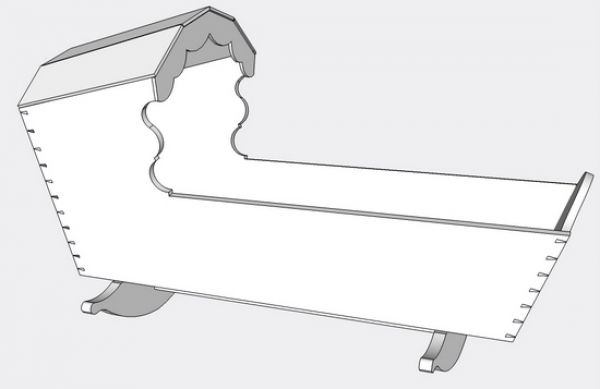
Last week I attended the Colonial Williamsburg Conference, “Working Wood in the 18th Century. Covering the subject – Bedroom Furniture – I found this conference very educational and valuable. One of the featured furniture pieces was an 18th C child’s cradle. It looked simple enough, however after working with the design, I’ve found it to be one of the most complex and difficult. I haven’t built it yet, only within SketchUp, which is in itself, a challenge indeed.
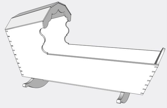
Here is an overall view of the design in SketchUp. As Bill Pavlak, the Williamsburg Cabinetmaker, remarked: “This piece has no right angles. ” In the following steps, I’ll show my method of creating this design in SketchUp.
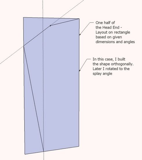
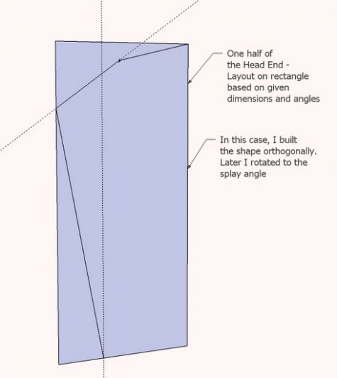
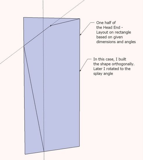
Step 1: I started with the Head End of the Cradle. Since this piece is symmetrical about one axis, my strategy was to build one-half the cradle as split down the middle, then complete with a simple copy and flip.
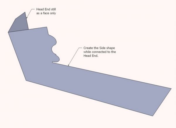
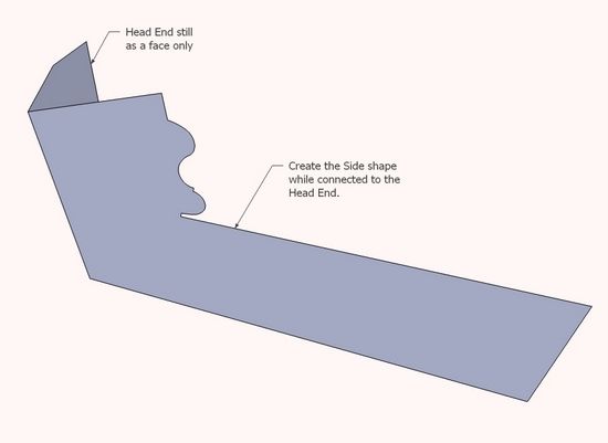
Step 2: Using the Head End as a reference, I began the design of the Side in its splayed position. Note that I’ve kept the components as “faces” only at this stage. I found this made it easier to get the outline of the piece to specified dimensions.
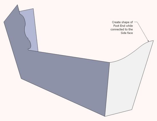
Step 3: Using the first two components as reference, I built the Foot End. Again I only created one-half the End component for efficiency in getting to the detail design.
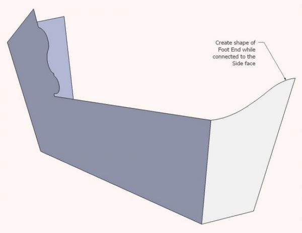
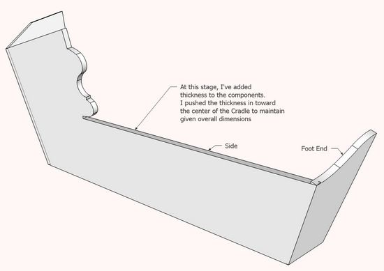
Step 4: At this stage I push/pulled each component to specified thickness. I pulled into the interior of the cradle to maintain the overall lengths and widths of the original design.
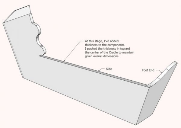
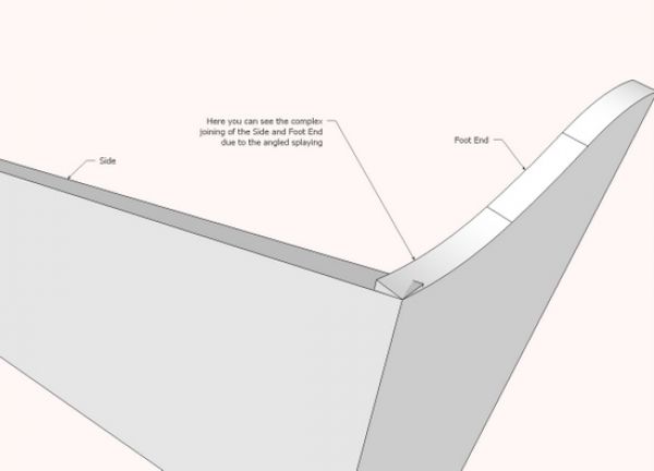
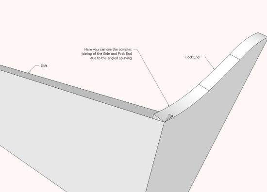
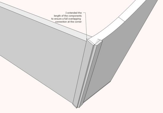
Step 5: Now it starts to get complicated. Notice the connection mess at the corner due to the multiple angles and splaying. This corner will be dovetailed so there will be quite a process to clean up and join cleanly.
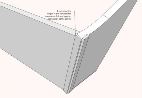
Step 6: Since the components do not totally overlap, I need to slightly extend them to ensure the overall length and width specifications of the cradle. The ends of these components require beveling before making the dovetails.
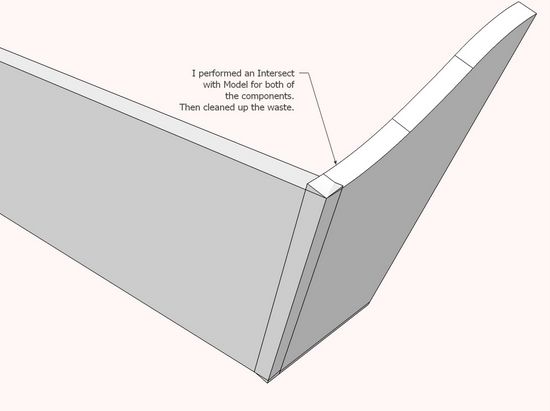
Step 7: I executed “Intersect with Model” for both of these components and then removed the waste. I did not clean up the top and bottom surface as these protrusions will be smoothed in the shop with a file.
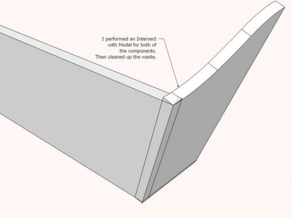
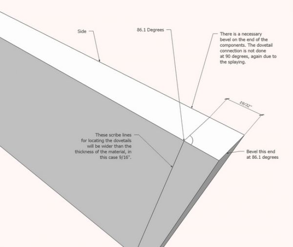
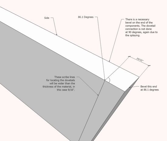
Step 8: Here we can see the result of the beveling that occurred in the intersection. Note that the angle for beveling is now settled in SketchUp and this is an important piece of data for the shop work. Also I can see in SketchUp where to place my dovetail scribe lines and the setting of the marking gauge.
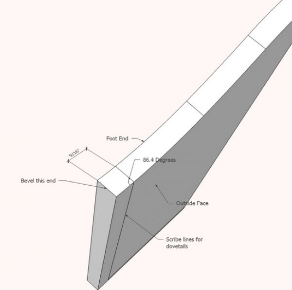
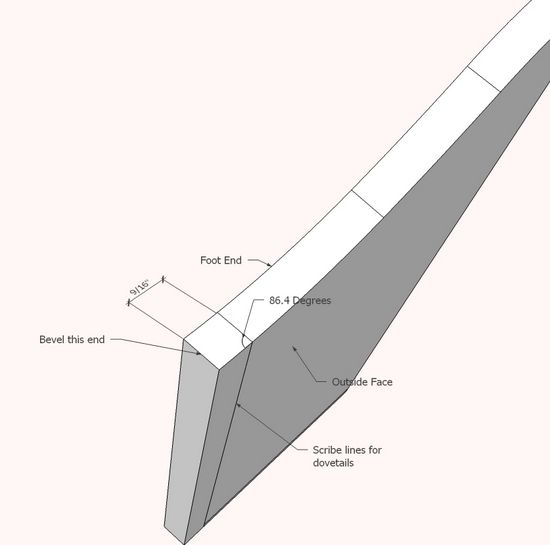
Step9: The same is true for the Foot End – the bevel angle is now determined.
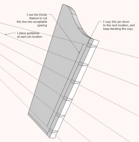
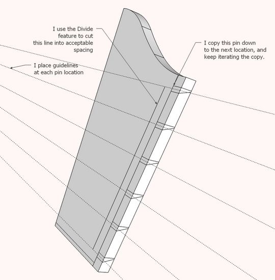
Step 10: The dovetail pins can be created on the Foot End. Unfortunately, one of these pins must be created line-by-line. We can’t use Push/Pull as this will push the pin at the wrong angle. The layout of pins is such that it roughly lines up with the horizontal axis regardless of splay.
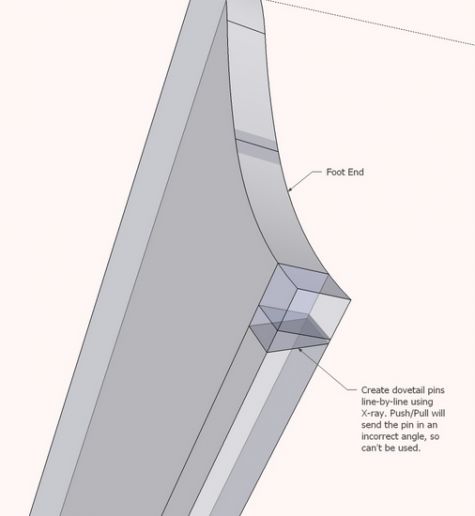
Step 11: In this step I copy the pin location at accurate spacing.
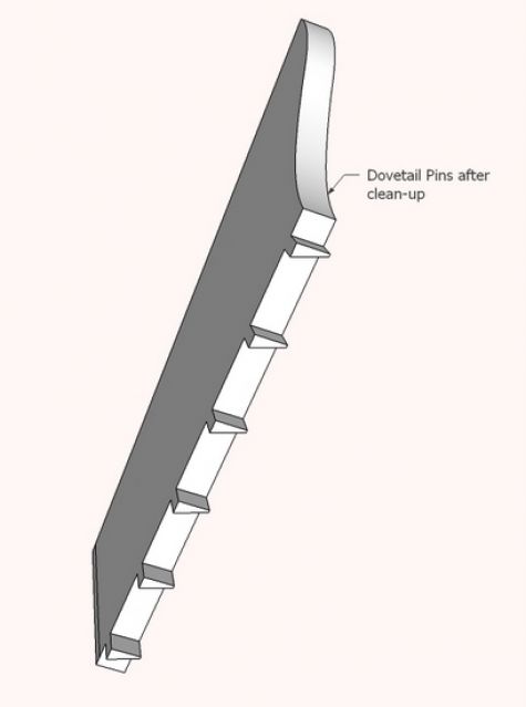
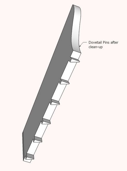
Step 12: Here are the pins after clearing away the waste.
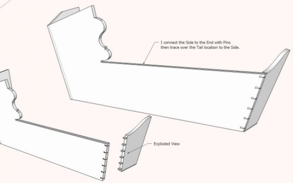
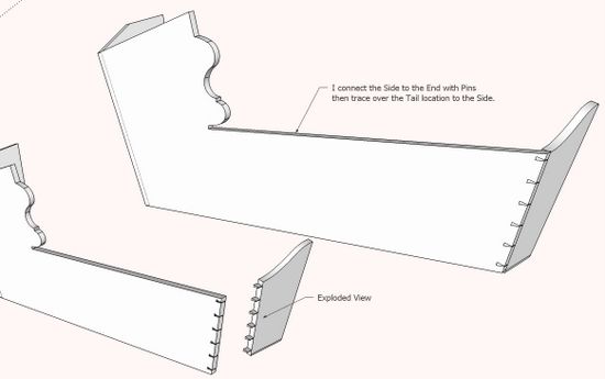
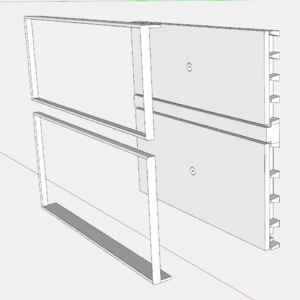
Step 13: In the final step, I’ve created the tails in the Side component.
Once the design is complete, SketchUp will be invaluable in providing full-size templates for shape and dovetail layout.
Again Williamsburg has been an inspiration – the high standards of craft and professionalism are very much appreciated.





Comments
I absolutely loved going to the conference the last 2 years. I like the child's cradle, but the senility cradle was creepy that they showed in the 2nd session.
You are spot on with you sketchup rendition! You amaze me with your sketchup models.
Scott
Log in or create an account to post a comment.
Sign up Log in