Now that you’ve got your piece of furniture modeled in SketchUp, how do you extract/ show information and drawings needed in the shop? For this you need to know about SketchUp “Scenes” which allow you to define, capture, and save multiple views and details that, when printed, provide a comprehensive document for use in the shop.
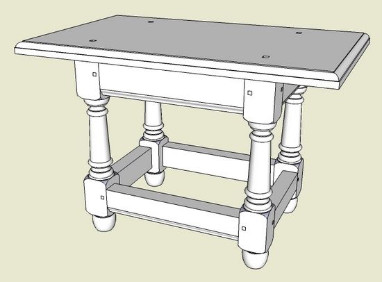
As an example, I will show the development of a shop documentation package for a Connecticut Stool as shown below

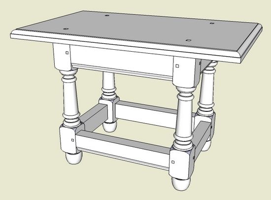
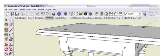
Below is the above assembled view of the stool as displayed on my computer. I’ve cropped the screen picture so you can see the horizontal set of multiple tabs just under the Toolbar. These tabs are labeled Cutting Diagram, Scan, Orthographic, Assembly, Exploded, Leg, Front Stretchers, Lower Edge on Stretchers, Side Stretchers, Top, and Edge Molding on Top. In this model there are 11 of tabs or Scenes. (For more complicated pieces, I may have as many as 50 scenes). When you click on the tab, SketchUp displays the selected detail or view that was saved for that Scene. For this small piece, 11 pages are sufficient for construction, and along with a cutlist make up the entire shop documentation.

In the process of creating the model, I am continually developing views needed in the shop. I don’t separate modeling tasks from developing documentation, rather these activities are very much blended. Nevertheless, I often get into construction and find that another specific view, cross-section, X-ray, or close-up would be helpful. For this, the computer, handy to the shop, is used to quickly generate the new view.
How do you create a Scene? First, I find it useful to have the Scenes’ dialog box on my screen at all times. Click on the Window tab and in the pop-up menu, select Scenes. A dialog box will appear on the screen. Minimize the dialog box by clicking the mouse on the top heading bar. Then drag the minimized Scenes’ dialog box up to a blank space in the top of the screen. Click on the minimized bar to expand the dialog box when needed for creating or editing a scene.
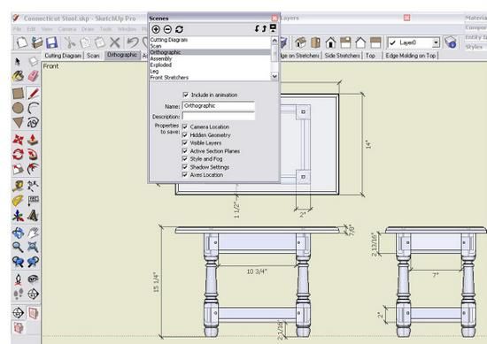
Here is a view of my computer screen with the Scenes’ dialog box expanded over the Orthographic view of the stool.

To create a Scene, follow these steps:
1. Orbit, zoom, and pan to set up the desired view of the model or component.
2. Click on the minimized Scenes’ bar to open the dialog box.
3. Click on the plus sign icon to add a new scene.
4. Type the name of the scene in the Name text box. You can also add a description, however I generally skip this.
5. Save the scene by clicking on the update icon with the “circular arrows”.
After following this process, a scene tab will appear just below the toolbars. No matter where you are in the model, clicking this scene tab will adjust the camera to retrieve the exact previously saved view.
As you can see in the above Scenes’ dialog box, there is a running list of all scenes. You can delete, add, and re-order the sequence by clicking on the up and down arrow icons. I generally follow a standard sequence of scenes for my models, and they are typically in an order that would be used in shop construction. That is for this table, after showing the overall and exploded views, I start with the leg component, followed by stretchers, and finally the top.
I will continue this subject next week and describe the dimensioned component drawings, cutting diagram, cutlist, templates, printing, and how I use Layout for construction packages.




Comments
Question: Do you add the dimensions on Layer 0? Or, do you keep the dimensions on various layers depending on the scene? It seems the model would get very cluttered if all dimensions were visible all the time.
Tim
I look forward to your further tutorial on this subject.
I hope you can address the use of CutList Plus. I am having trouble to get it recognize rough lumber in the cut list/layout
Thanks in advance
Richard
Great subject to discuss! I need lots of help but love SketchUp and want to make more use of in in the shop. Could you also also go through building the exploded view?
DaveS48: I generally keep my dimensions on Layer 0 and outside the component definition. There are occasions where I need a close-up view of the component to more easily see detailed joint dimensions. I don't want these detail dimensions to show in the overall component view. So I will set up a layer for detail dimensions. Then I can set the Scenes to show or not show this specific layer.
When I make the detail dimensions, I originally make them on Layer 0. Then I click on the dimensions and flip the Layer to the detailed one. This procedure avoids my creating graphics on the wrong layer when changing the active layer and forgetting to reverse it.
Tim
docparm: I will cover the CutList but not sure I will be able to help you with the "rough" lumber. I do not show rough thicknesses in the cutlist, only the thicknessed dimensions. I do show rough thicknesses in my Cutting Diagram however.
Tim
DiveMike: I will indeed be showing the steps I use to create the Exploded View. Nothing fancy here, and it only takes a couple minutes to pull a copied assembly apart. Components are a must for doing this.
Tim
Tim
Although Ive been using SU for about 18 months I have never used layers so I welcome this tutorial. When you put dimensions on a layer do you mean without any geometry. do you make dimensions into components Will you be going through the basic process of putting items into layers Ihave managed to do it but do not find it a very logical process
Ted Gibbs
Teamman: Yes, when I place dimensions into a specific layer other than Layer 0, it is the dimension itself that is moved, not any graphics or components. I click on the dimension (or multiple dimensions in a view) and use the Layer Toolbar to switch them to the alternate layer.
I do not place my dimensions into the component, with a couple exceptions that are explained in a previous blog entry (URL below).
http://finewoodworking.taunton.com/item/7025/rules-for-dimensions
I hadn't planned on showing details on using and placing items into layers. This is a big subject and perhaps we need to have more information in future entries.
In the meantime, here is a previous writing by Dave Richards on Layers.
http://blogs.taunton.com/n/blogs/blog.aspx?nav=main&webtag=fw-designforum&entry=78
Tim
Tim
When I move a component in the second scene I've created, it's moving the same component in the first scene.
What am I doing wrong? I want each scene to be handled individually. Sketchup is able to hide components in the second scenewith out affecting the first scene, but as soon as I move something in the second scene, the first one is updated also.
What am I doing wrong?
Ken
Ken,
Take a look at the image at this link: http://finewoodworking.taunton.com/assets/uploads/posts/2364/FP_Cabinet_Overall_xl.jpg from my blog entry here: http://finewoodworking.taunton.com/item/2364/creating-a-project-plan-in-sketchup
In it you can see my set up for a cabinet with exploded views and so on. In the lower left corner you can see the entire cabinet. that was the original drawing in that case. Then I copied the model to another location in the drawing space and pulled that copy apart to make the exploded view.
If you move the components in your original copy of the model, they will show that way in any scene you make. You need to make a separate copy of the model to explode for the exploded views.
Hopefully that will give you some ideas.
Dave
Log in or create an account to post a comment.
Sign up Log in