Tim Killen’s recent blog post about making construction drawings in SketchUp brought up some questions about adding dimensions and using layers. I wrote some about making construction drawings in this blog post. Here’s a little more.
Both Tim and I create scenes to show different parts of the model. There are exploded views and details. Usually I create 2D views along with perspective views. It all depends upon what I need to show in the specific scene. Layers are used to control the visibility of various elements in the model. For example in a mode of a cabinet with drawers, the drawer components would be associated with a layer so that the interior of the cabinet can be made visible.
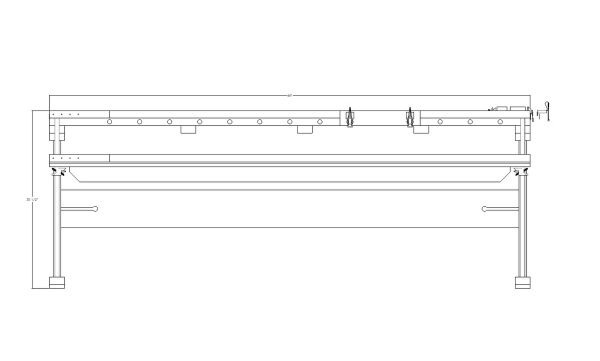
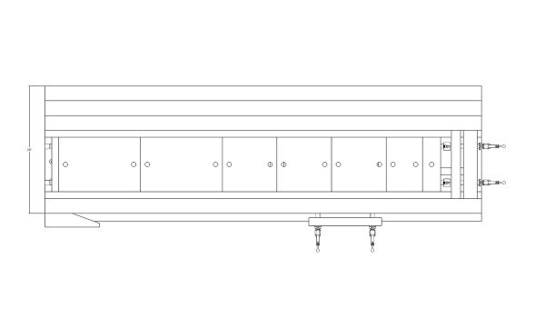
When it comes time to add the dimensions, I associate them with specific layers so their visibility can be controlled as well. I might show height and width dimensions in a 2D front view. The depth dimension would be shown in a 2D top or end view.
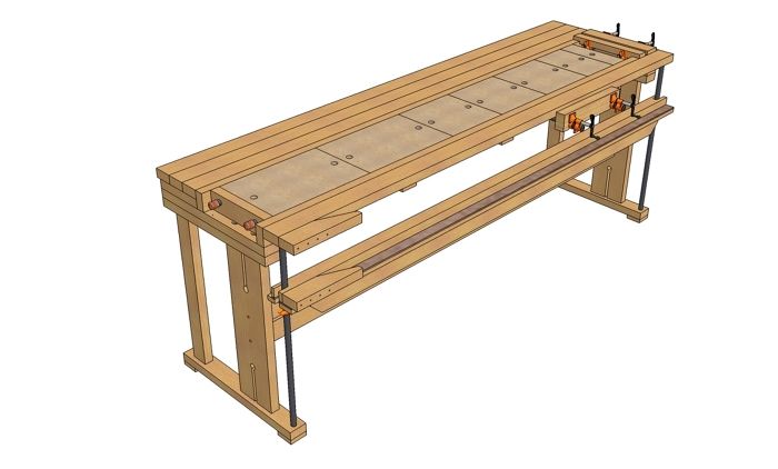
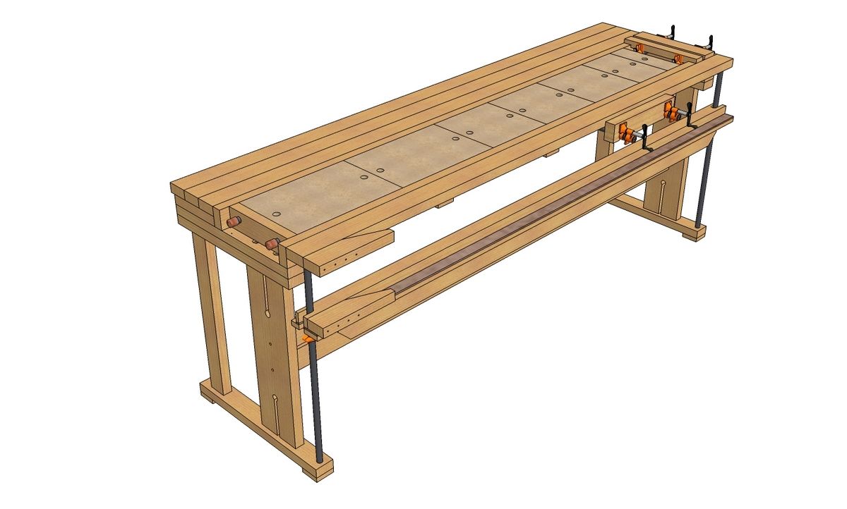
Here are the first three scenes from the construction drawing document I did for the popular New-Fangled Bench by John White. I just changed the camera position for each scene. The fist scene shows just the bench.
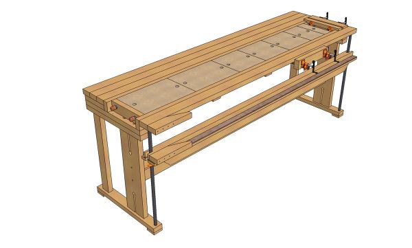
For this view I don’t want any dimensions visible. The dimensions that are visible in the next two scenes are on separate layers and the visibility of those two layers is turned off for this scene.
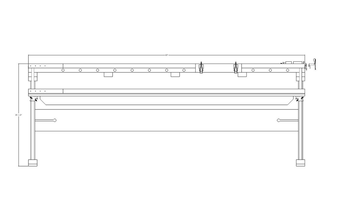
In the next view, the front view dimensions are turned on but the top view dimension is turned off.
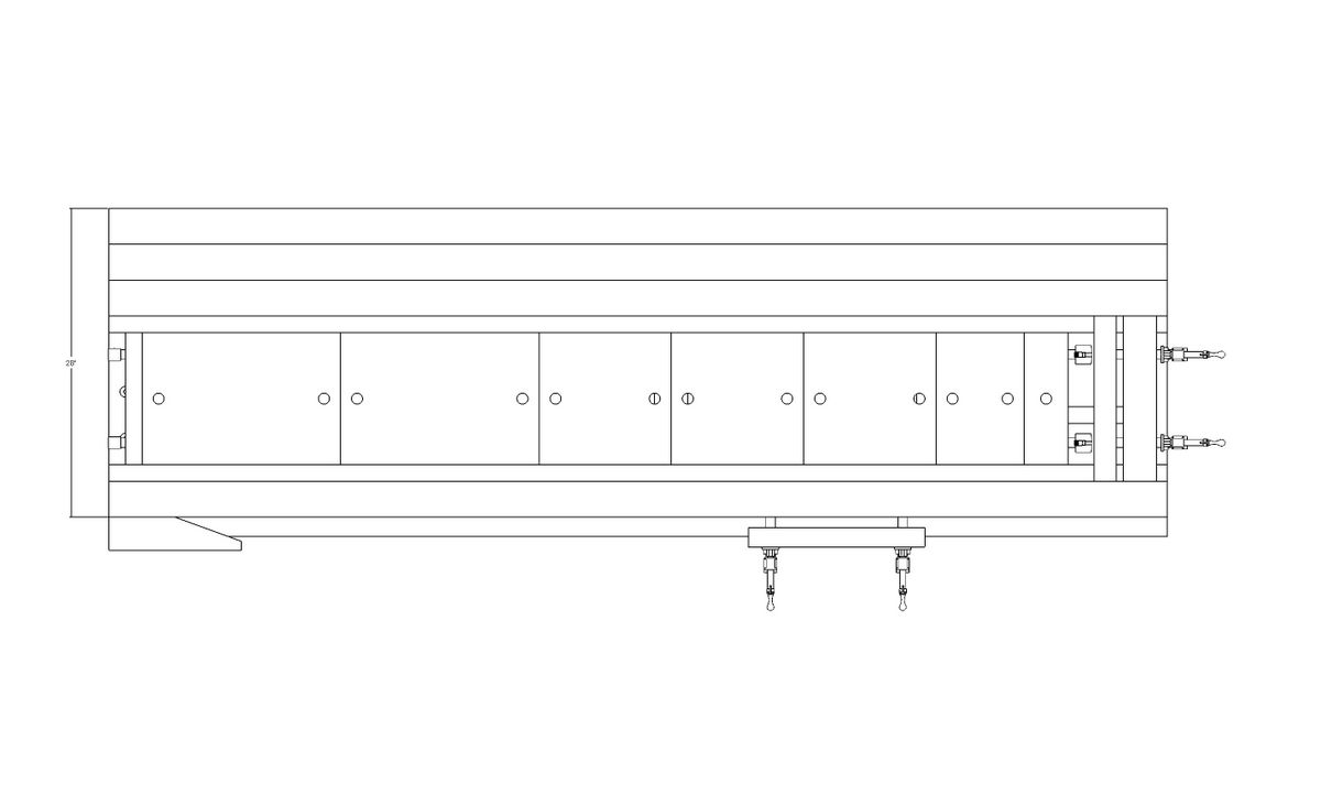
And, in the top view, the front view dimensions are turned off and the top view dimension turned on. This same sort of process is continued throughout the model.
Among the layers for this model are specific dimension layers such as “Front View Dims” and “Top View Dims”. Although I didn’t do it in this case, I normally name dimension layers so they appear in the Layers dialog along with the layer associated with the components to which the dimensions refer. There is a layer called Legs and a layer called Legs Dims. Sometimes I might have a scene that shows a close up view of some detail. The dimensions for the details would probably be difficult to read in a large view so those dimensions will be made invisible for that larger view.
I also copy the model to another part of the drawing window to make an exploded view. The exploded view is simply done by moving the components away from each other. Sometimes a view willl show other parts in the background. In order to clean up the view it is handy to be able to turn off the visibility for those background items.
My practice when dealing with layers in SketchUp is to follow the guidelines from the SketchUp folks. this is what they have to say.
First things first: by default, a SketchUp model has one layer, Layer 0 (zero), which is the base layer. You can’t delete or rename Layer 0, and you should always draw your individual entities on Layer 0 and leave them there.
The main difference you’ll notice is that entities associated with different layers in SketchUp still intersect each other. For this reason, it’s almost always best to draw all your individual entities on Layer 0 and leave them there. Then, if you want to use layers to organize your model, you can turn individual entities into groups or components, and then associate different layers with those groups or components. To add additional layers:
- Open the “Window” menu.
- Click “Layers.”
- In the “Layers” dialog box, click “+” button
- Optionally, you can rename a layer (other than Layer 0).
- Optionally, you can delete a layer (other than Layer 0). If the layer you are deleting isn’t empty, a message asks if you want to move its contents to another layer or delete the contents.
- Optionally, you can make another layer active by clicking its option button. When you draw individual entities, they are always drawn on the active layer, so you should typically have Layer 0 selected, unless you need to hide it, in which case, you need to select a different layer.
Important note: Groups and components are also entities, and, just like with individual entities, you control their layer properties in the Entity Info dialog box. To try to keep things clear, this article refers to individual entities (things like edges and faces) versus groups and components. To try to make things even clearer, since groups and components behave the same with respect to layers, only groups are mentioned from now on in this article. Finally, the idea of drawing individual entities on Layer 0 and leaving them there is so important that this article doesn’t even address the option of associating other layers with individual entities. If you want to experiment with that, you’ll need to take along your own search and rescue team!
Notice the way this is phrased: you associate layers with groups, rather than moving groups to layers. This is because a layer is actually a property of a group, and you associate a layer with a component/group by selecting it in the group’s Entity Info dialog box.
Once you have associated layers with components/groups in a model, you can use the layers to control the visibility of those compoents/groups. In this way you can easily turn off or on the visibility of various parts of your model, for example, you could make all of your wall and roof entities different components/groups, associate layers with those components/groups, and then hide those layers so as to display just the floor plan in the model.
To control the visibility of layers:
- In SketchUp open the “Window” menu.
- Click “Layers.”
- Click the check box in the “Visible” column: when it has a check mark, the layer is visible; when it is clear, the layer is hidden.
Note: The active layer is indicated by its option button being selected. You can’t hide the active layer, but you can select another layer, and then hide the original one.
Additional notes about layers:
- Be happy! Always draw your entities on Layer 0 and leave them there. (Did we say that already?)
- Controlling visibility versus isolating geometry. It’s important to note again that layers control only visibility. You can’t isolate geometry (make it independent of other geometry) by associating different layers with it; you can only control whether it is visible or hidden by making the layer that is associated with it visible or hidden. The way to make selected SketchUp geometry independent is to make it into a group or component.
- Keeping track of layers with color. When you are associating layers with groups, you can make it easier to keep track of the layers by turning on layer colors:
- Open the “Window” menu.
- Click “Layers.”
- In the Layers dialog box, open the options menu, and then select “Color by Layer.”
- If you are following the advice to draw all individual entities on Layer 0, and then leave them there, all individual entities will have the color of Layer 0. All groups or components will have the color of the layer they are on.
- If you select the Paint tool, Color by Layer is automatically turned off.
- Entities within groups. If you draw some entities on Layer 0, make them a componentgroup, and then associate another layer with the component/group, the entities within the component/group remain associated with the original layer. However, the group controls the visibility of the entities. If you hide the layer that is associated with a component/group, all of the entities within the group are hidden. Also, if you use Color by Layer, the color is controlled by the layer that is associated with a group or component.
- Color by Layer with groups that are nested within other groups. If you have Layer 0 associated with a component/group, and then nest that group inside another group, the Layer 0 group will inherit the layer color of the topmost component/group. If you have a layer other than 0 associated with a group, then that group inherits and keeps that layer’s color, even if you nest it with another component/group and associate a different layer with the topmost component/group.
I always leave Layer 0 as the active layer so the only way to control visibility of dimensions is to associate a different layer with them. The number of layers used depends upon the complexity of the model and for whom I am making the construction documents. If you are making construction drawings for your own use you may find you don’t need to include as much detail as you would if they were being made for someone else to follow.



Comments
Thanks for your help Dave! You hit right on some fundamentals that were giving me fits. These basic program structure issues were getting me into trouble. I am encouraged to press on.
Mike
Hi Mike, Glad to know that helped. Keep plugging away.
Dave
Hey, Dave, do you know the guy that designed Cutlis 4.0. If you do, would you pass along my suggestions to him.
I was having trouble with the board foot calcs and found out that the program calculates BF incorrectly. In the formula, (length x width x thickness)/144, the thickness should never be less than 1. Cutlist uses whatever is listed in the thickness column. I could calculate the BF correctly if the inch mark(") was removed from the dimensions. The dimensions cannot be used in formulas with the inch marks present. I could remove them manually but that is very cumbersome in a large projet. Why offer the .CSV option in the program if the data is restricted like this. The inch notation could be made in the column heading, i.e. length(inches).
Thanks, Dave
Randy Morgan
Hi Randy,
You can force the board foot calculation to look at all components less than one inch thick as if they were one inch by checking the 4/4 box at Use Nominal Sizes. Click on the Layout tab and then the Boards tab to get to it. Then also check other nominal sizes as needed for the thicker parts.
Remember you can also determine whether thick boards will get split as well as wide boards. there are settings for board width and length as well.
Dave
Thanks, Dave for the advice regarding the BF calcs in Cutlist.
Do you know why dimension columns will not sort correctly in cutlist. Other colums sort as they should. Is it the number marks (")or am I missing something else.
Thanks, again you are a great resource for all of us.
Randy, could you send me the CSV file that is giving you trouble? I'll take a look.
Dave
I should think the program is pretty awesome as an instructional to other people! For me, I love how the clean side profiles incorporate the removal of confusion with other layers involved in the construction. It makes for very clear-cut diagrams that leave no room for misinterpretation.
Log in or create an account to post a comment.
Sign up Log in