
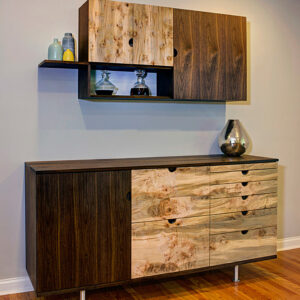
SketchUp models with complex shapes and compound curves can be daunting to draw but by breaking them down into smaller parts the process can be greatly simplified. Recently I was asked for some ideas on how to draw this drawer pull. The front face was the hang up. As with many things in SketchUp, there are probably several ways to approach drawing this. Here’s one way that works for me.

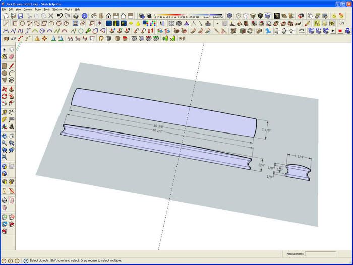
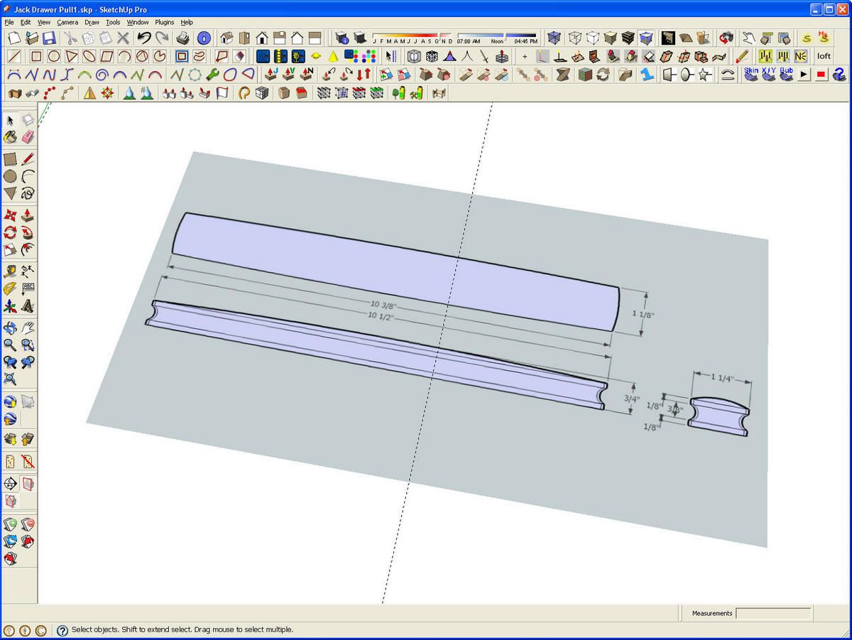
This image, above, is what was sent to me as a JPG file. I imported it into sketchUp as an image so it would be handy as a reference. Tim Killen and I have both demonstrated tracing over an imported image. I could have done it with this one but I found it was easier to draw it from scratch. Importing the image is required for this but it saved me from either printing it or switching to an image viewer application to look at it.
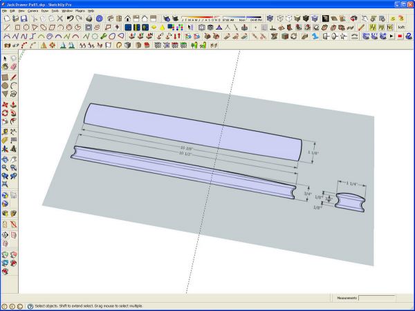
So here’s what it looked like after importing the image. I didn’t concern myself with how large it is. I didn’t want it so large that I couldn’t see it and the model at the same time.
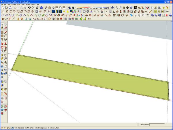
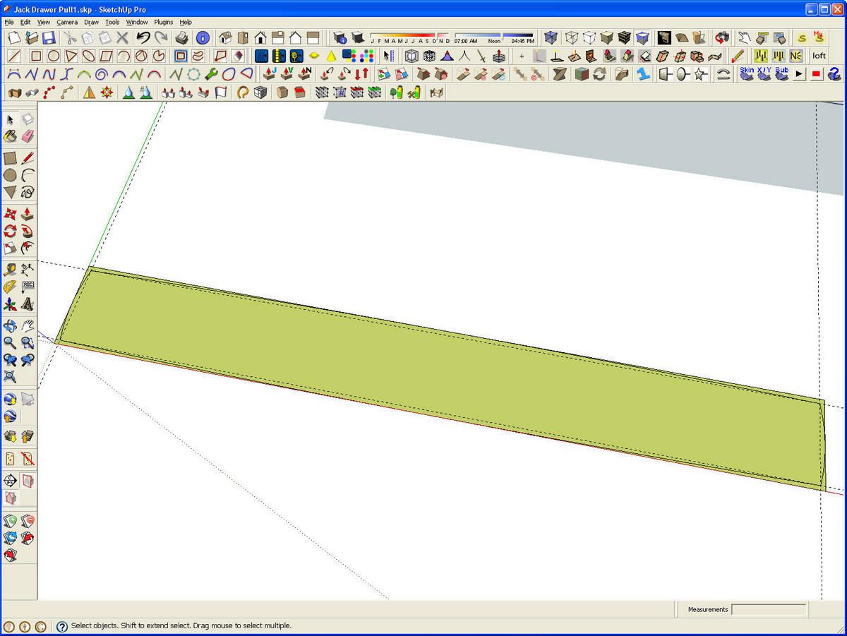
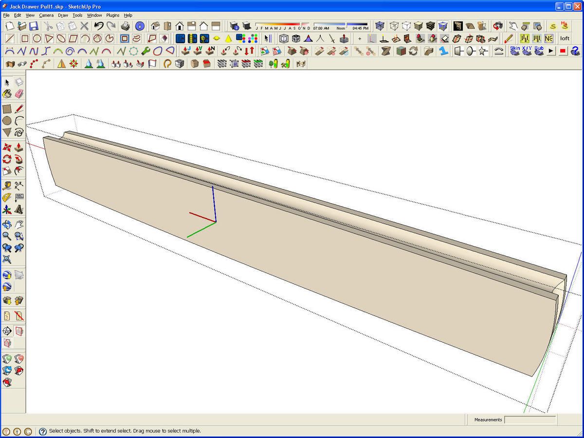
Now we get busy drawing. I drew a rectangle to the overall dimensions of the pull. Then I used the Tape Measure tool to set out some guidelines 1/16 in. in from each edge. The intersections of these guidelines are the end points for the arcs that come next. After the arcs are drawn in, the corners and the gudelines are deleted. this leaves the footprint of the pull.
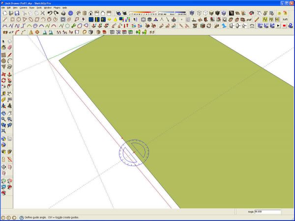
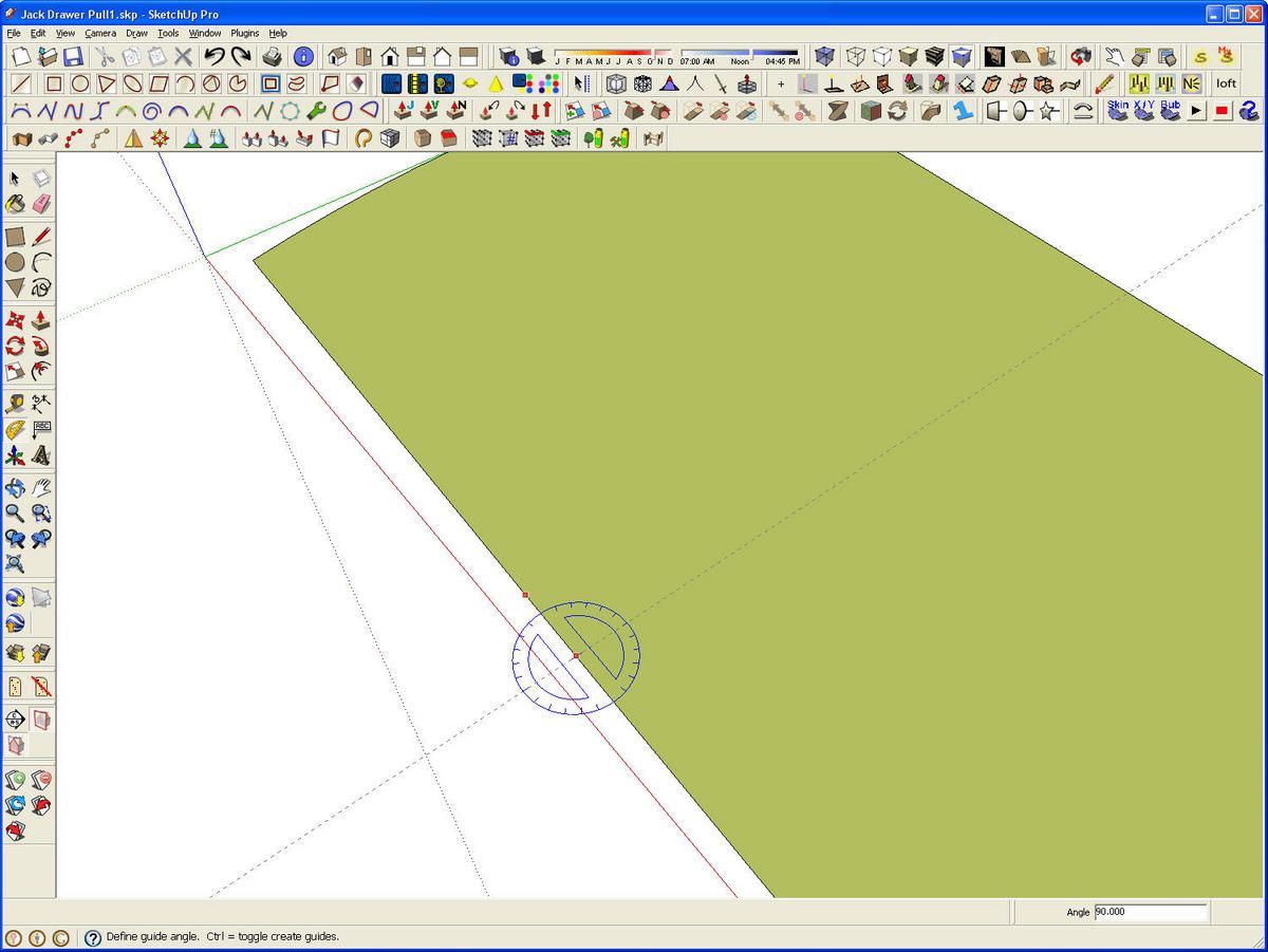
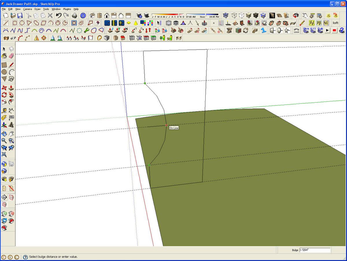
Next I zoomed in fairly close. I used the yellow Protractor tool to place a guideline perpendicular to an edge sgement. This guideline is the basic alignment guide for the edge profile that will be used with Follow Me. Placing the profile perpendicular to the first line segmenof the Follow Me path prevents unexpected results later.
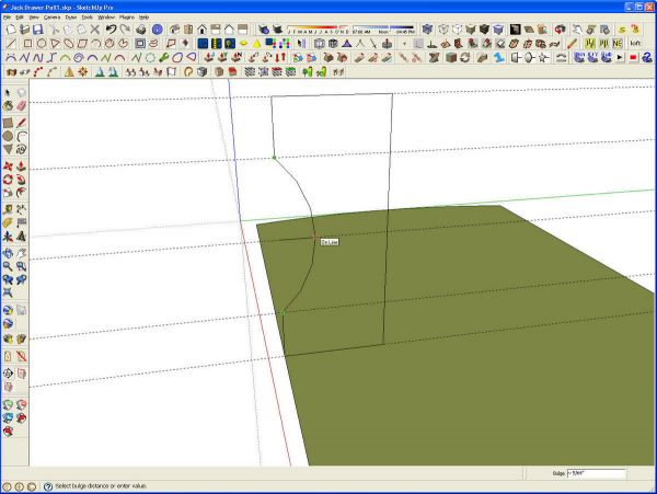
I added a few more guidelines to assist in the layout of the profile. These additional guidelines were dragged up vertically from the first. When you do that you need to make sure you are moving in the blue direction. You may find that adjusting the camera position will make it easier to do this. Notice I put a guideline in at the midpoint of the arc. Since the profile is being drawn just a tiny bit off axis, this guideline helps ensure that edge of the arc is coplanar with the other edges of the profile. If the arc isn’t coplanar, the face won’t fill. The arc was drawn using only six sides/segments. There’s no need for the full 12-segment arc for such a small detail and this will help to keep file size down.
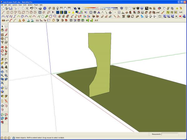
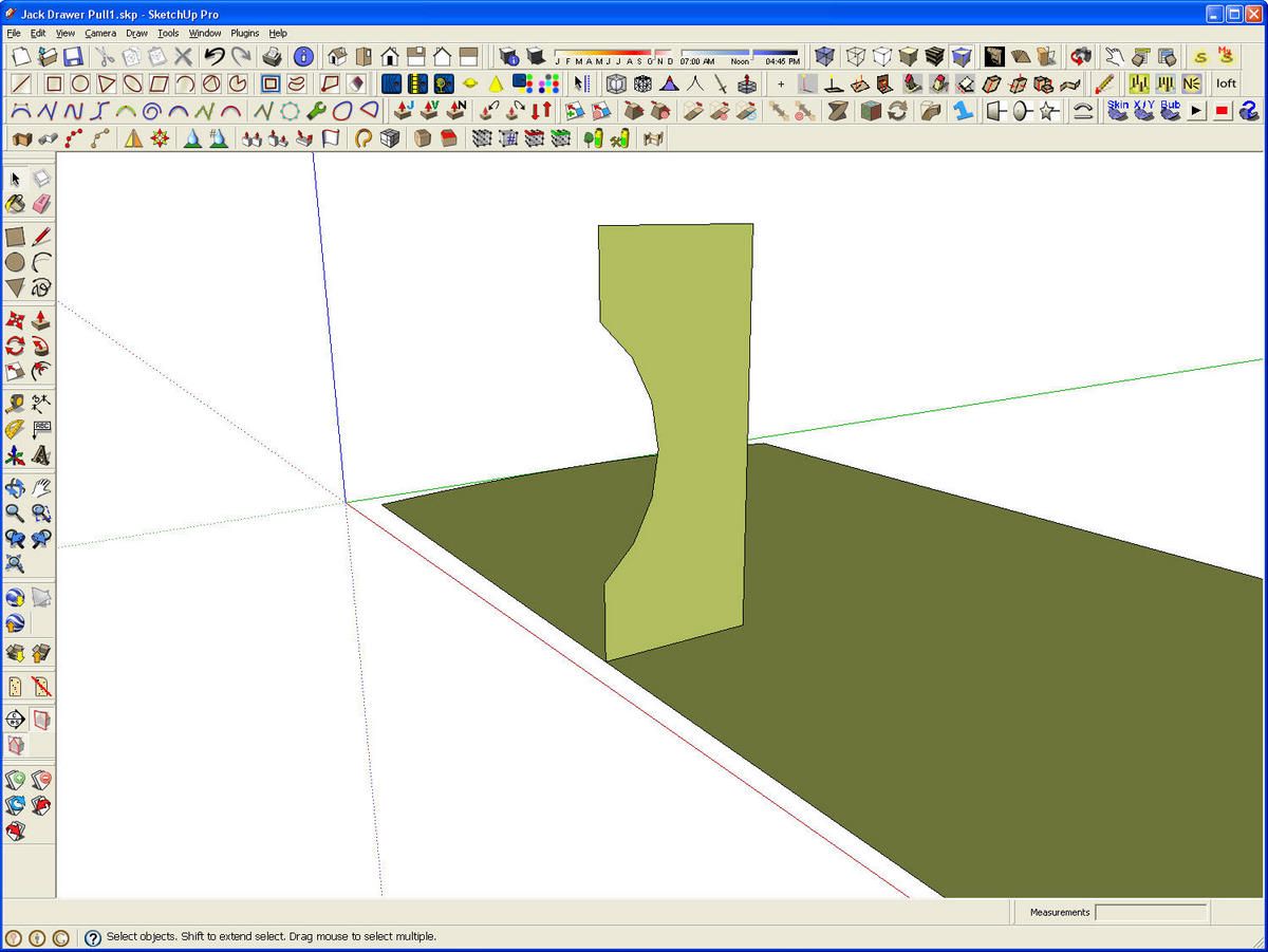
The profile is now drawn so the next step is to run the Follow Me tool. I like to preselect the path, the edge of the horizontal face in this case, before getting the tool. A double click with the Select tool on the horizontal face will work just fine. Then we get the Follow Me tool and click on the profile face. I have the F key set up as my shortcut for the Follow Me tool.
Note: This pull is symmetrical over its length. At the end the pull is going to be made of two halves. We create only half of this part of the pull at this point. I think it is easier to see how the pull develops by drawing this part as the whole thing and spliting it later.
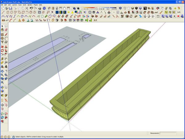
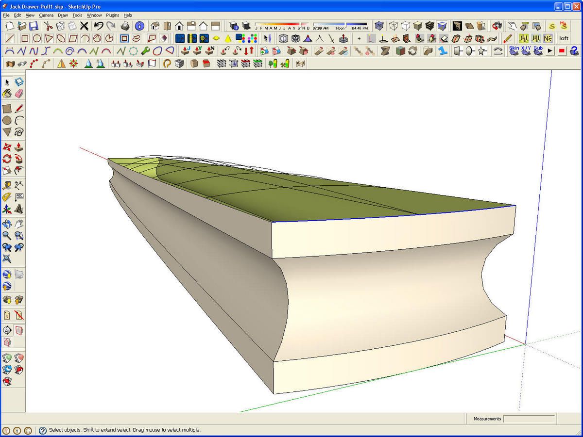
Here’s the result after Follow Me. I selected the top face and deleted it. Then I selected all of the internal geometry and deleted that. Since there was an exisitng face at the bottom, the Follow Me operation ended up deleting it leaving the bottom open between the inside wall and outside edge of the extrusion. This is normal because the Follow Me tool is both additive and subtractive. After deleting the face on the top, I triple clicked with the Select tool on the interior geometry to select all of it. Then I hit the Delete key and it was gone.
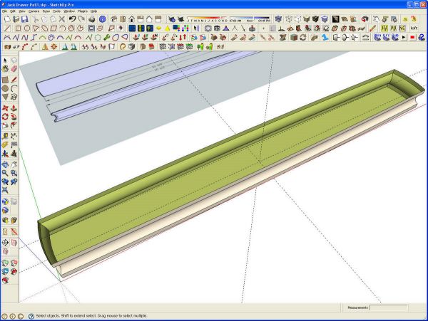
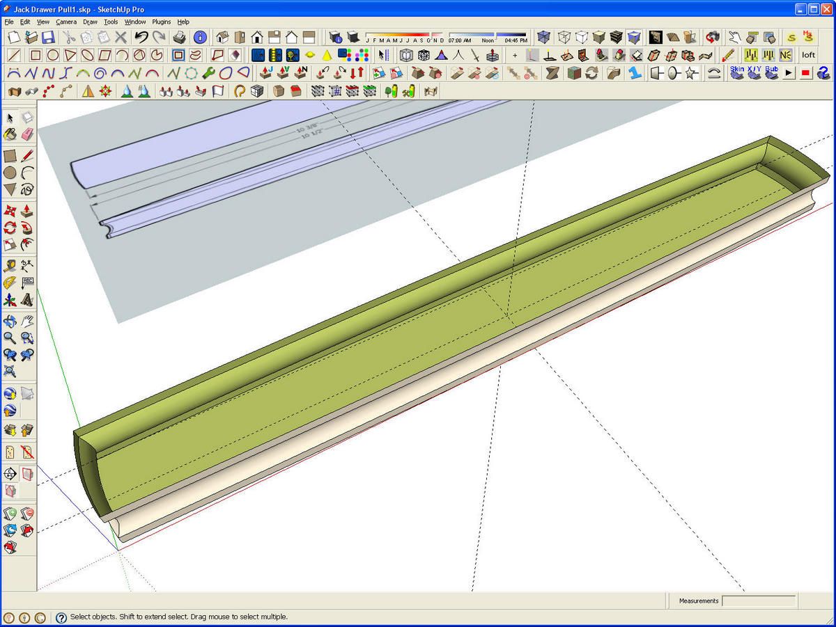
I healed the face on the bottom of the pull by tracing one of the edge segments with the Line tool. Next I corrected the face orientation. I use that popular 70s appliance color for the back faces in my models. This makes it easy to see when I have faces reversed and when there are holes in the model. I made the geometry to this point a temporary group. I normally use only components but for temporarily isolating or protecting geometry I want to reference to but not modify, a group works fine. It will be exploded later.
I also laid in a few guidelines for the next steps. One of those guidelines is set at 3/4 in. above the base which is the overall thickness of the pull.
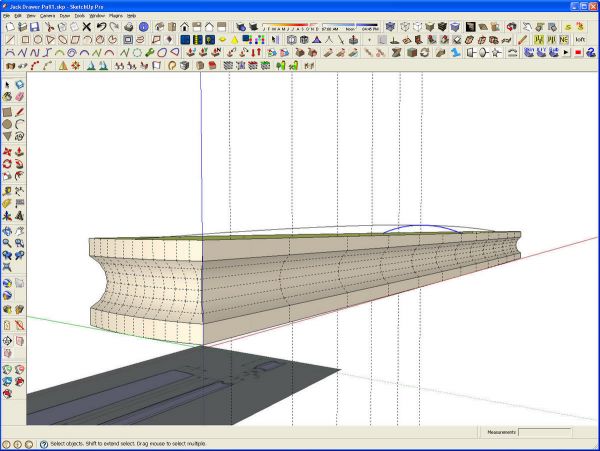
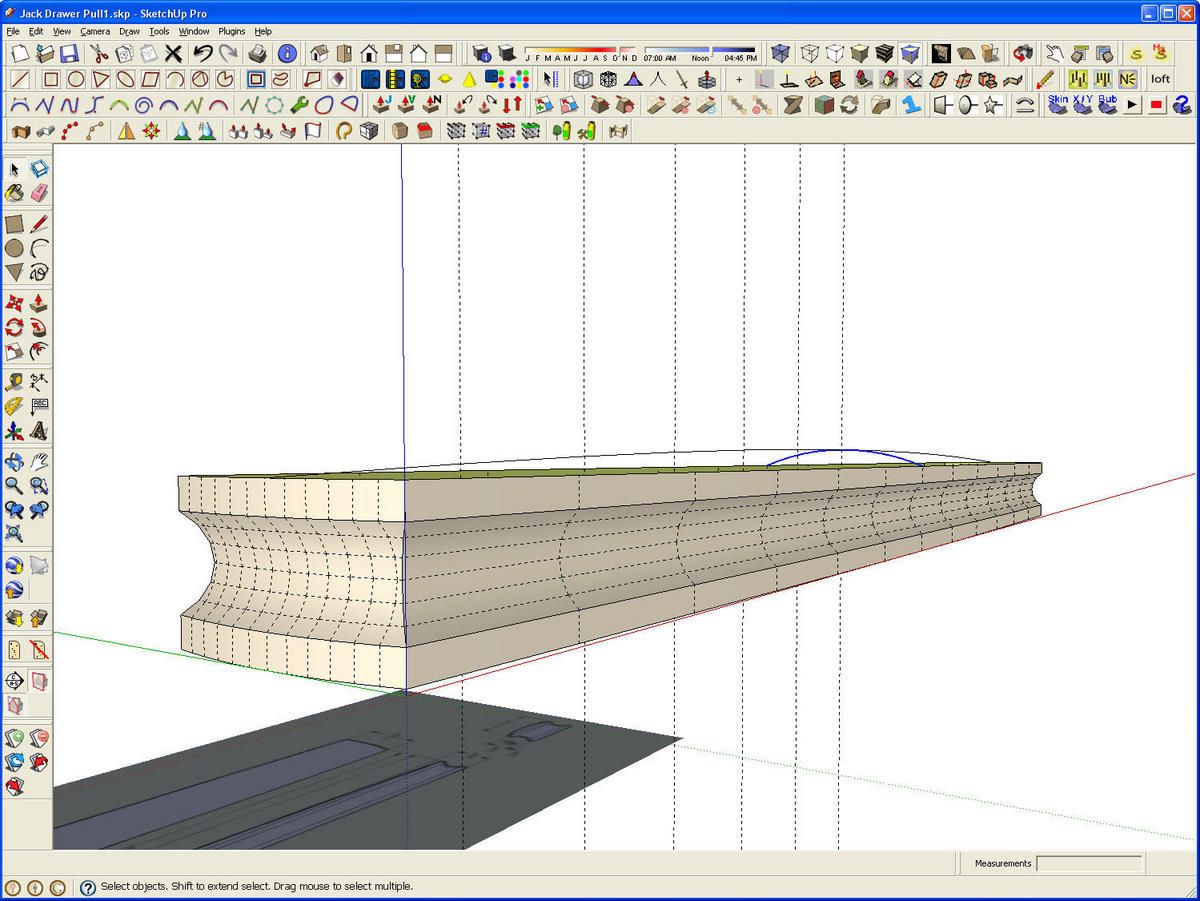
Next I drew a 12-segment arc the length of the pull and up to the crossing guidelines and made it a group. This arc is only a reference and will be deleted later. I put in a few more vertical guidelines that intersect the long arc at the nodes or intersections of the line segments. After that I placed the arc running across the short dimension of the pull at the center of the pull.
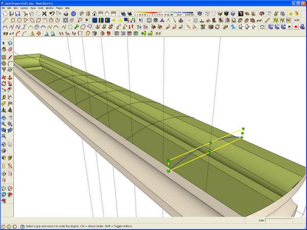
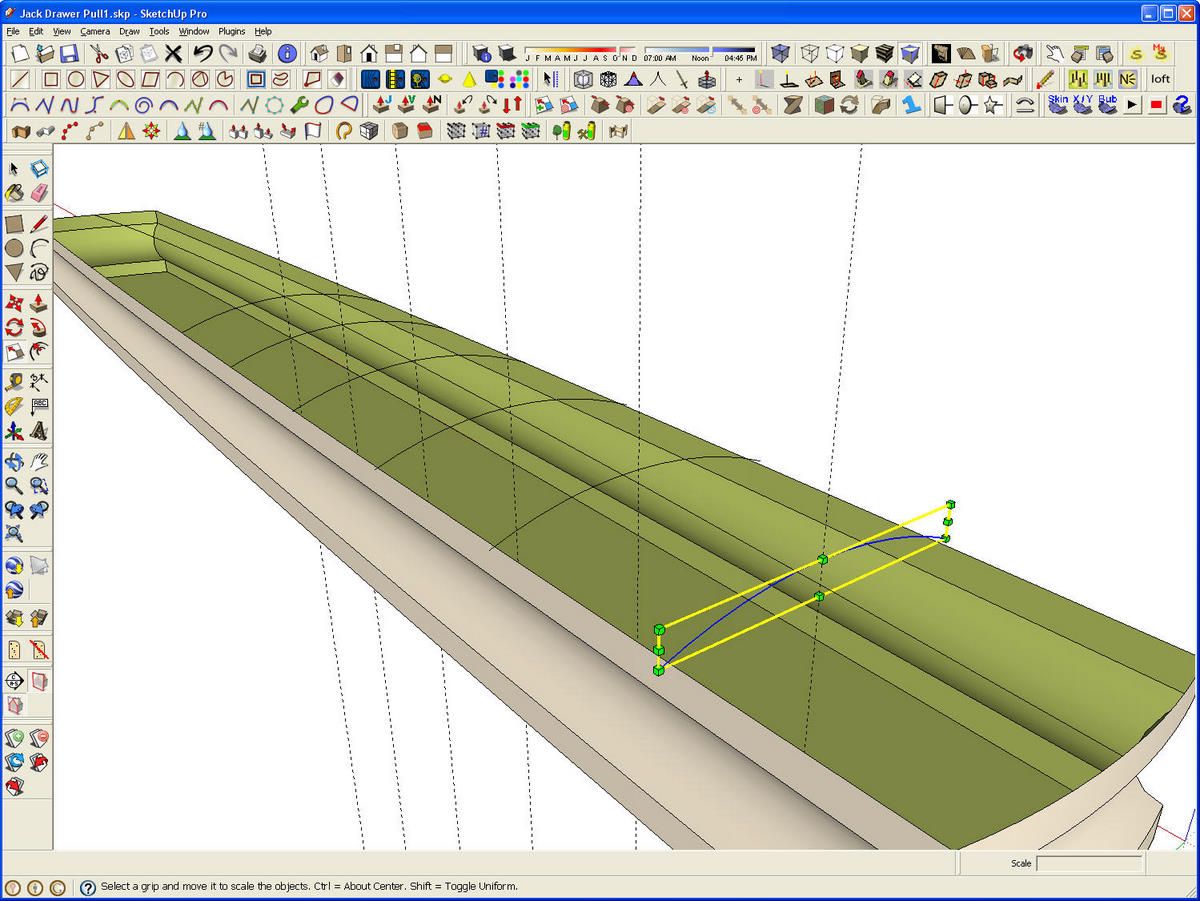
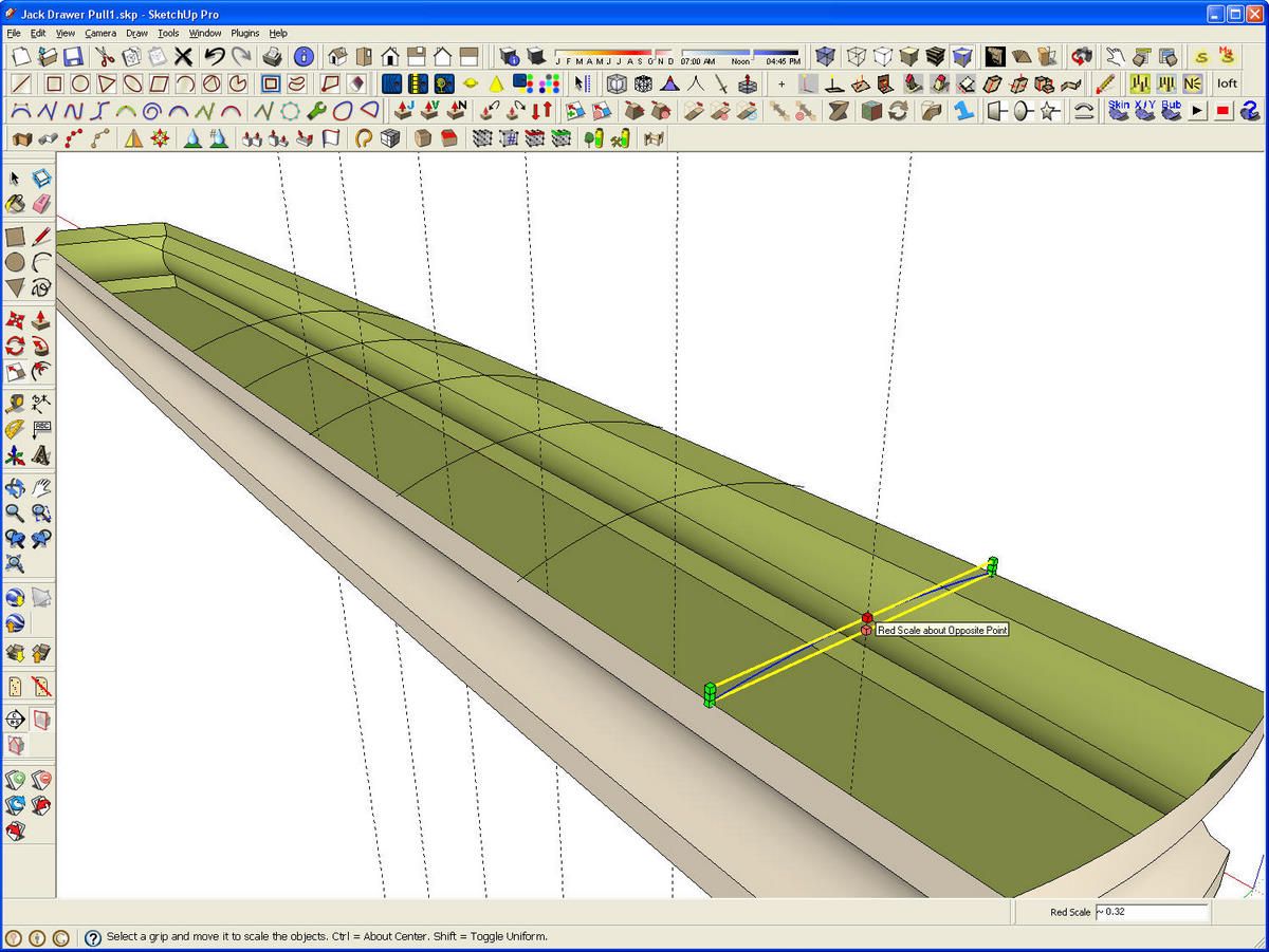
I copied the short arc down the length of the pull placing the copies at the nodes of the long arc. Since the pull is symmetrical, we only need to do this for half of the pull. Then I scaled each of the arcs so their width matches the width of the pull at their position andtheir height matches the height of the corresponding node on the long arc. This is a two step process for each arc but it goes quickly. To scale the width of the arc, hover over the center green handle on the end and hold the Ctrl key (Option on Mac) to invoke Scale About Center. A little red cube will appear in the middle of the bounding box. Then push the end handle toward the center and move the curser down to the edge of the pull. The scale tool will snap to that point.
To scale the height, grab the top, center Scale handle and pull down until the tool snaps at the node on the arc. the vertical guideline is helpful as it makes the locating of the node easier to see but it isn’t strictly neccessary.
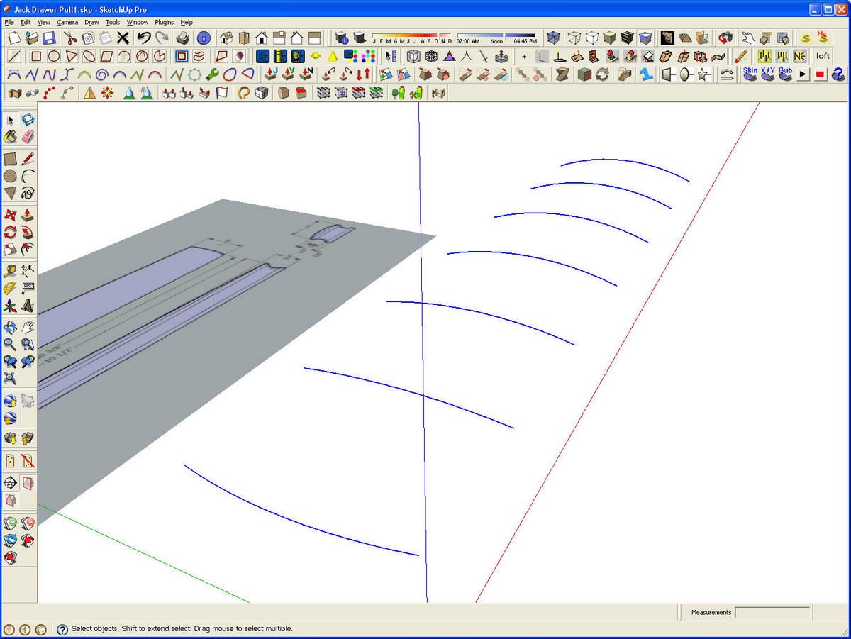
Repeast this scaling for the rest of the arcs. The one at the midpoint won’t need to have any scaling done.
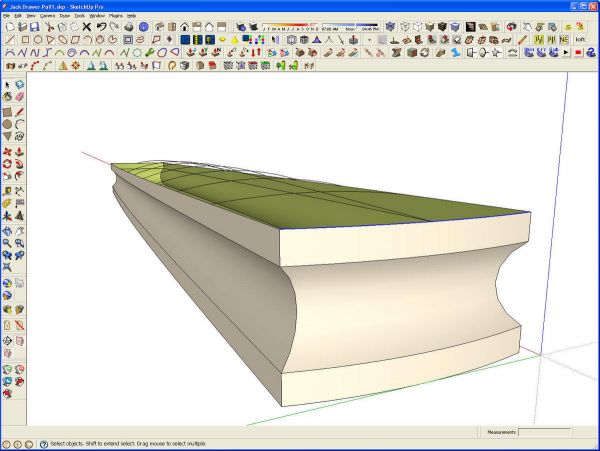
After the arcs are scaled, add one more arc by tracing the top edge at the end of the pull with the Arc tool. The next part of this has the potential to create some of those tiny faces that SketchUp won’t fill. So, before moving on, I scaled the model up by a factor of 100. To do this I drew a line 1 in. long with the Line tool. Then I measured that line with the Tape Measure tool making sure to click at both ends. The Measurement box display 1″ but I type 100 and hit Enter. SketchUp asks if I want to resize the model and I click OK. I save that line for later when I am ready to scale the model back down.
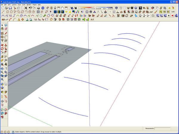
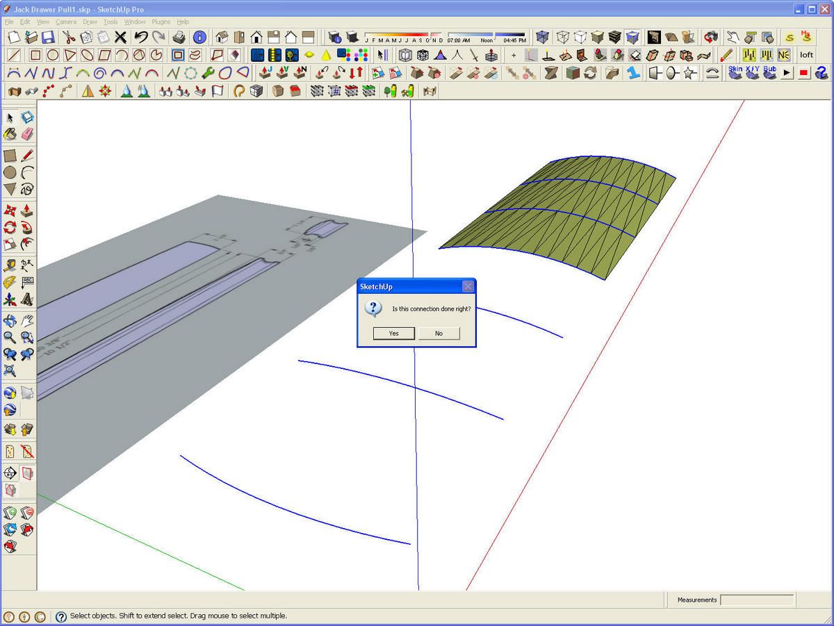
The long arc is no longer needed so I deleted it. I also hid the pull just to make the next steps clearer. I’ve selected all of the arcs in preparation for running the Skin plugin. then I activated the plugin from its toolbar.
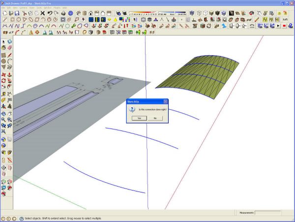
The plugin draws in the triangular faces between consecutive arcs. After completing the operation between each pair of arcs, a small message box pops up asking “Is the connection done right?” Since it is, I click Yes. then the plugin moves on to the next pair of arcs. This continues untill the entire skinning is completed.
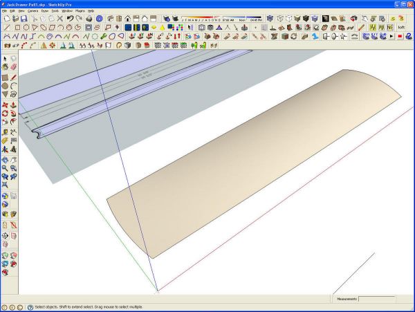
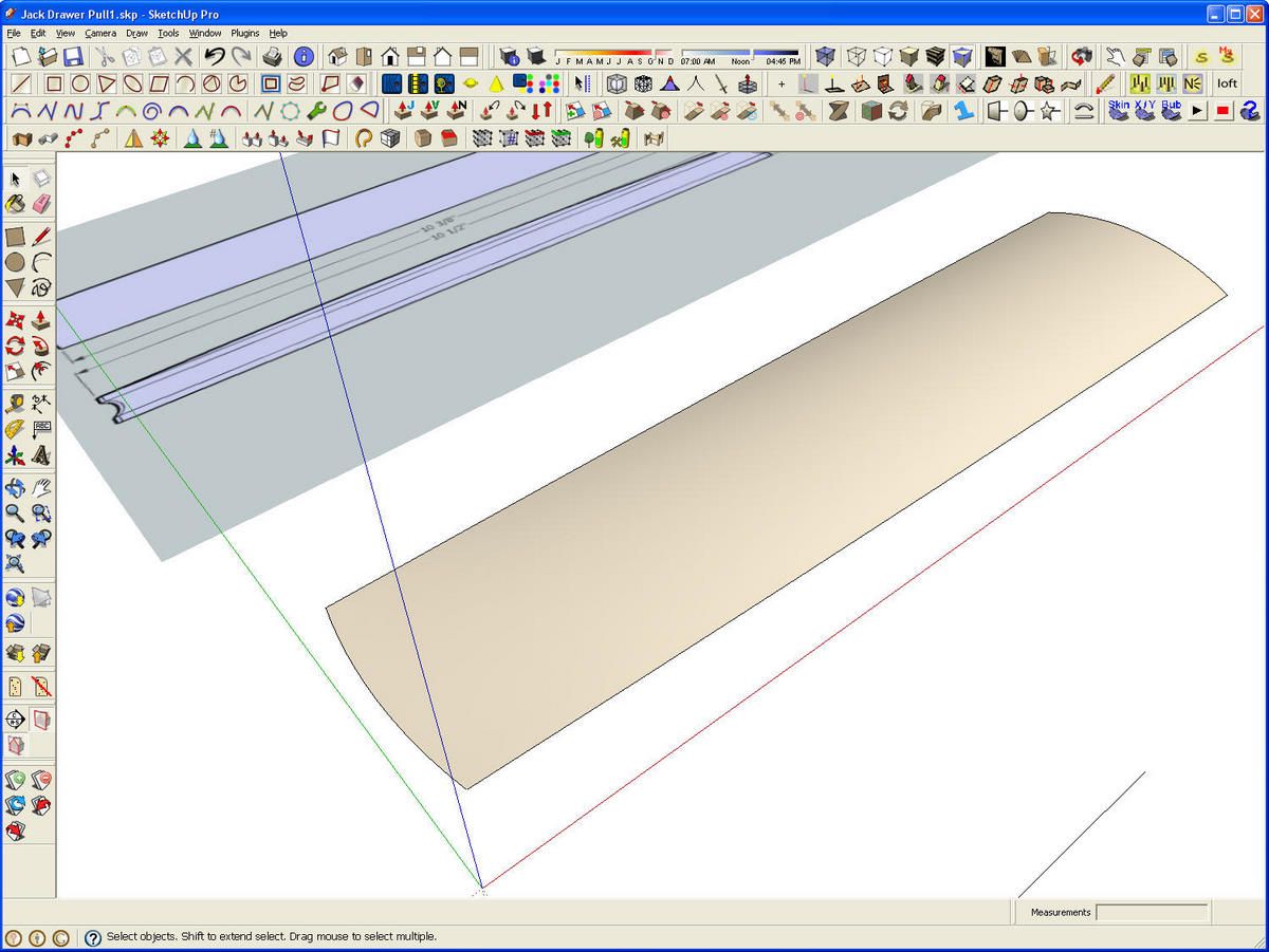
Once the skin is completed the face orientation is corrected as needed and the surface smoothed.
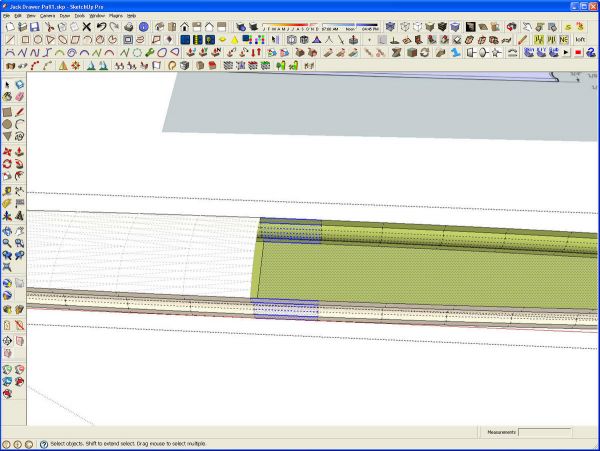
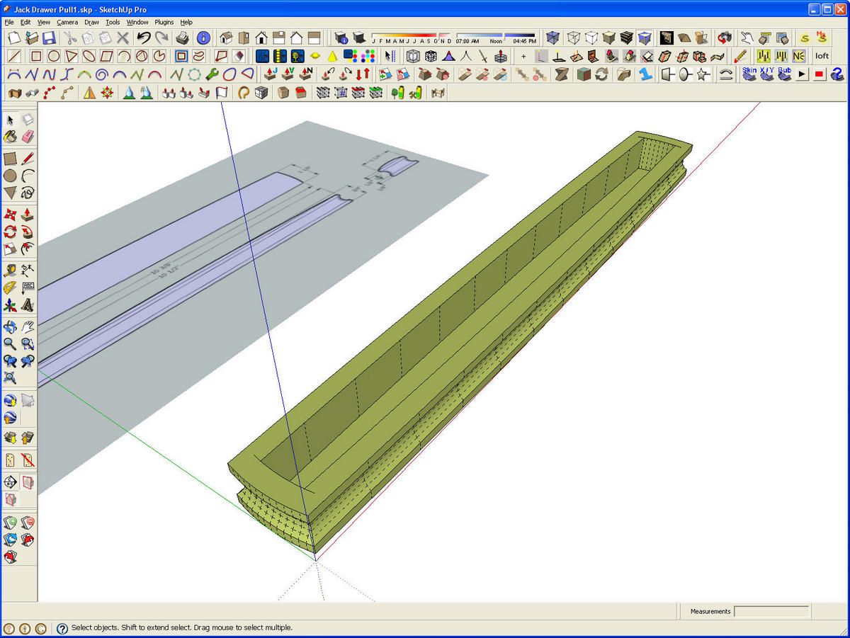
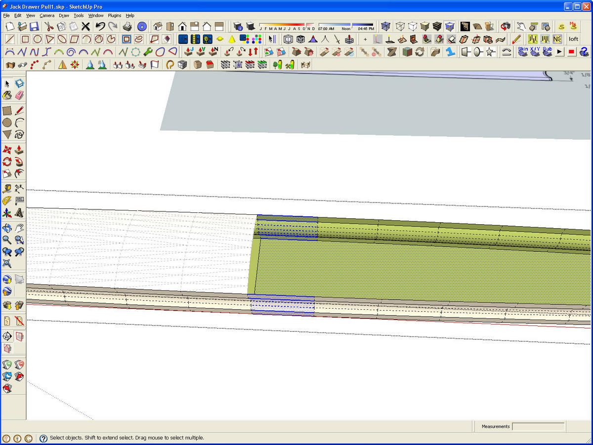
Here I am getting ready to delete half of the base portion of the pull. I’ve turned on Hidden Geometry and drawn a line across the bottom face. A right to left selection box was used to select the part shown in blue. I did this small section so the view would be close enough to see some detail in the small image but I would normally drag the right to left selection box around the entire end and then delete it.
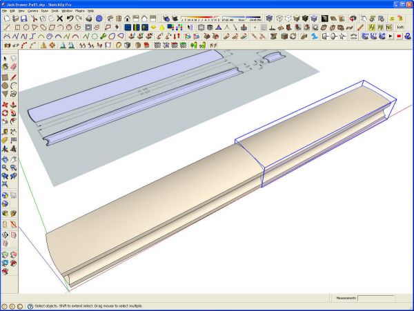
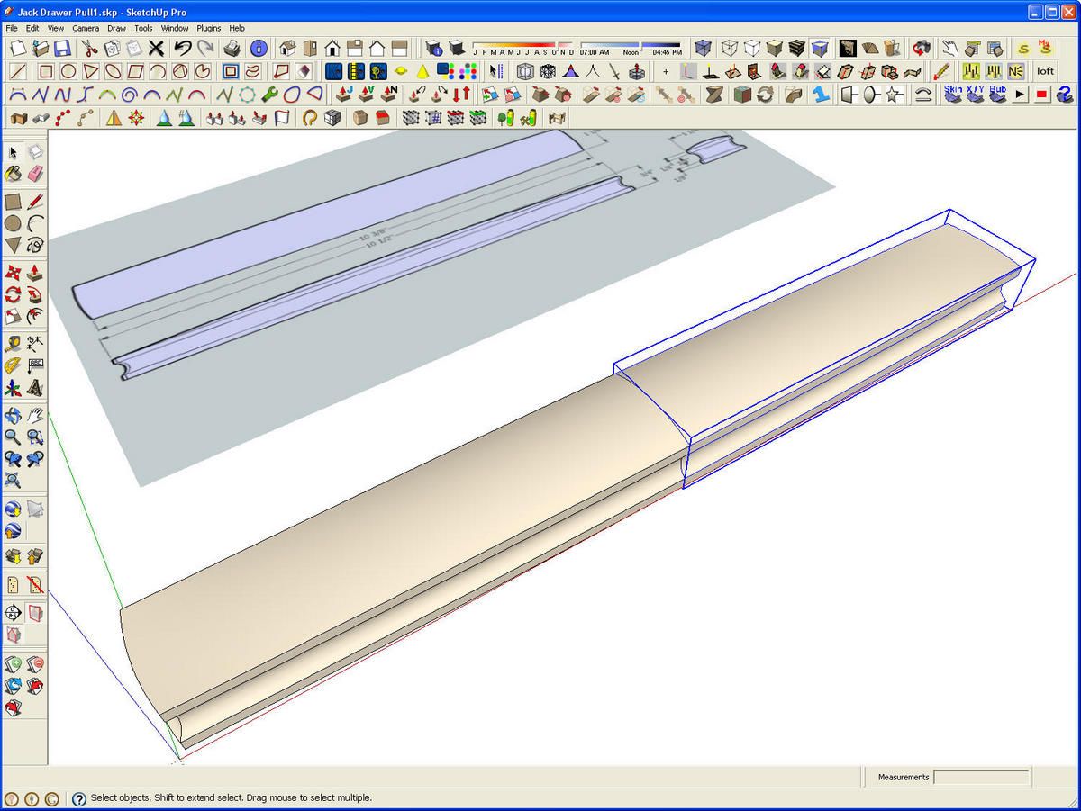
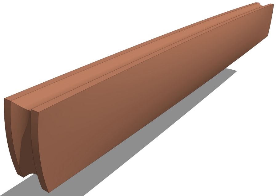
After deleting one half of the pull, I exploded the group. Then I selected all of the geometry and made a component. Then I copied the component, flipped it along its red axis and moved the copy to meet the original. I then opened one instance of the pull and hid the edges at the seam line by holding the Shift key while click on the edges with the Eraser tool. Then I selected both instances and made a nested component of the two.
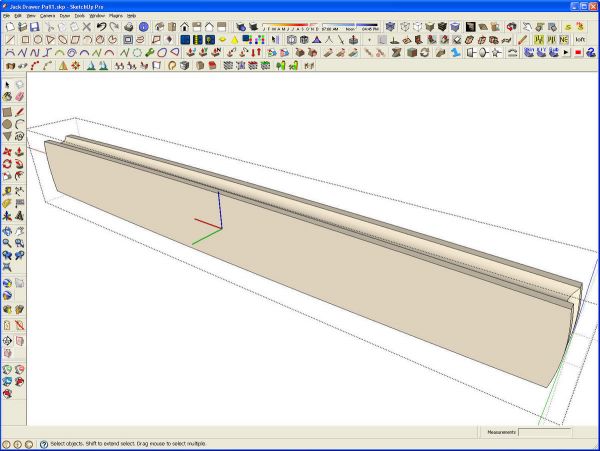
In anticipation of the pull being used in larger models, I took a moment to rotate the pull into and upright position. then I changed the axis locating the origin at the middle of the back face of the pull. The red axis is running lengthwise and the green running back away from the pull so that the blue is pointing up. The origin of the component’s axes becomes the insertion point when the component is brought into another model. This pull can now be easily positioned at the intersection of a couple of guidelines representing the center of the pull.
To save the pull for futre use, open the Components browser and its secondary pane. Set the top pane to In Model and the bottom one to the library into which you want to save it. Then click and drag the component from the upper pane to the lower one. Now it’ll be available for future use.






Comments
That's a fun project. I started from the jpg and got to the same place the same way. (That doesn't always happen.) I can't make my output look as good as yours though. Are the pictures of the model native SU output, or were those rendered with another program.
Thanks,
I'm glad you had good luck with this.
As to the image quality, most of those images are screen grabs. The two images of the pull in brown are JPG exports and the original 2D image with the reversed faces is what was sent to me. All the rest are direct screen shots though.
Log in or create an account to post a comment.
Sign up Log in