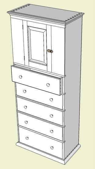
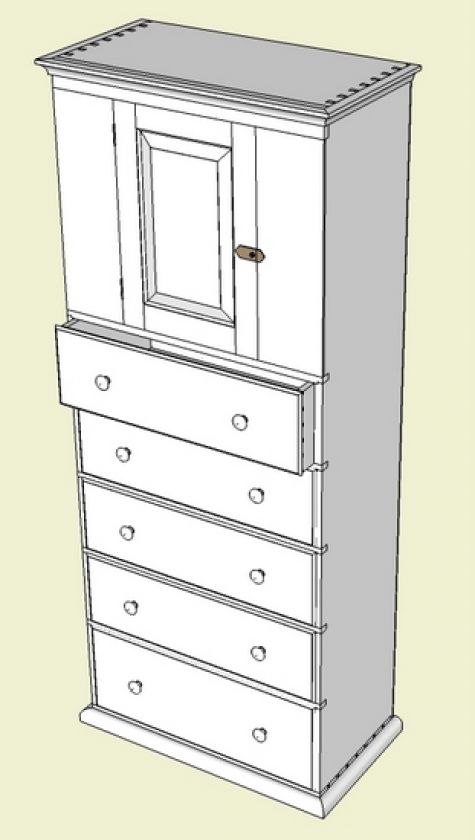
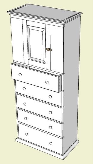
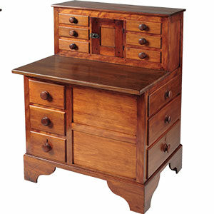
I don’t use a lot of cross-sections in my design documents, but occasionally I find them extremely effective. They are particularly useful where it is difficult, with normal visualizations, to see how things are fitting together. Here are examples of particular cross-sections I find helpful using this Shaker Cupboard Chest as an example.
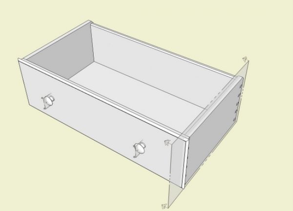
Drawer construction can be difficult to “see”, and I will typically create a cross-section view through the drawer side. First I will make the assembled drawer a component. With the assembled drawer selected and set for “editing”, I use the Section Tool, move the cursor to the drawer side, and click the mouse. You will notice that the Section Tool changes colors based on the cutting plane. In this case I want the cutting plane to be parallel with the face of the drawer side. Moving the cursor to that side face will automatically align the desired cutting plane.
Note that by placing the cross-section within the component, the cutting plane is confined to the component only. This is desirable to prevent the cutting plane from displaying over the entire model space.
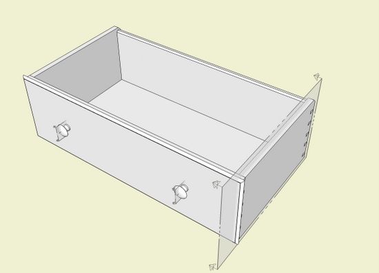
Here is the drawer with the inactive cutting plane showing on the drawer side. With the Move/Copy Tool, shift the cutting plane to the desired position within the side (this is done while the drawer component is being “edited”).
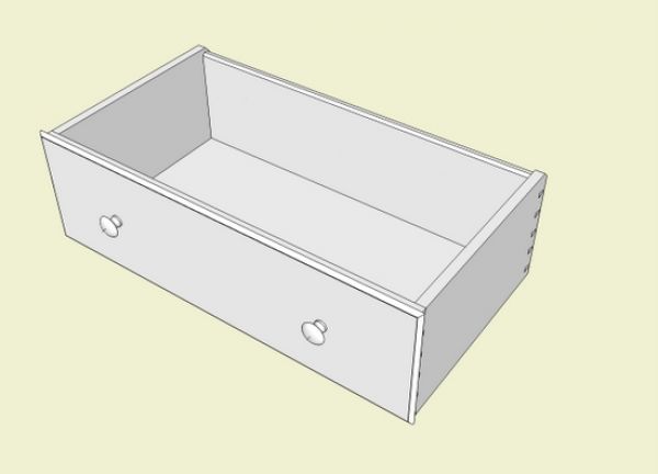
Since the cross-section is now within the component definition of the drawer assembly, every copy of the drawer assembly will show this cutting plane. But in the overall Cupboard Chest view above, I’ve used the drawer assembly component and the cutting plane is not showing. Often, I want to hide this cutting plane in component copies and to do this I use a new Style.
In the Styles dialog box, I create a new Style, and edit it to not show section cuts. After creating a new Style, and picking the edit tab, click on the last cube icon called Modeling Styles. In the pop up box uncheck the boxes called Section Planes and Section Cuts. Now save this new Style and also apply it to the specific Scene by updating the Scene.
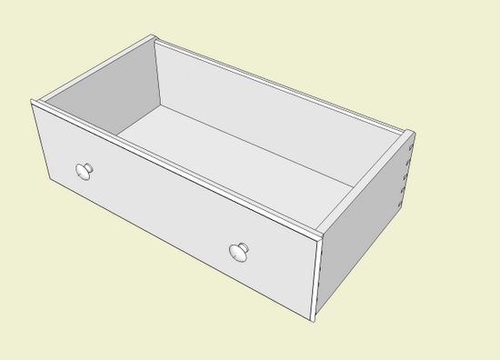
Here is the same assembled drawer without the cutting plane but in a different scene saved with the new Style.
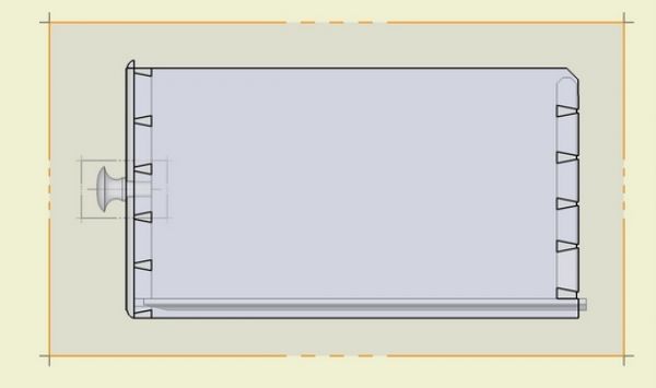
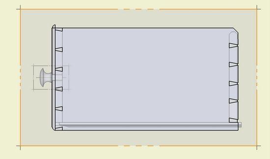
To show the active section cut, I set up a new Scene based on the standard right side camera position and set Camera to Parallel Projection. Here is the result, showing how the drawer bottom, front, and back fit into the side. With this view I can tell if there are any interferences or problems with the bottom groove and the dovetail joints.
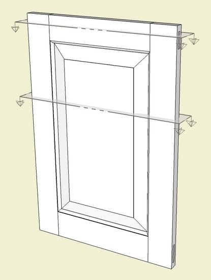
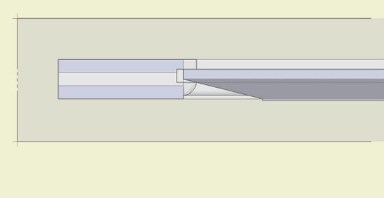
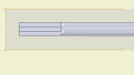
The door is another example where sections are helpful in visualizing the fit-up of the various parts. In this case, I’ve placed two sections within the door assembled component. I set up scenes for each of these section cuts by right clicking on the section and selecting Active Cut from the pop-up menu.
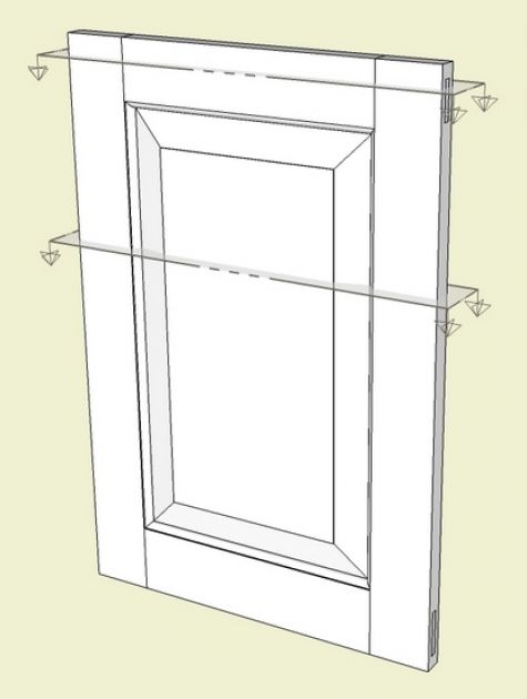
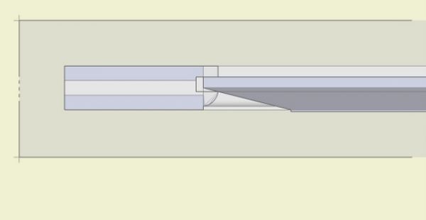
Here are the two scenes, one cut through the door panel, and the other through the upper rail. With these views, I can see how the beveled panel fits into the stile grooves, and also how much expansion space is available.
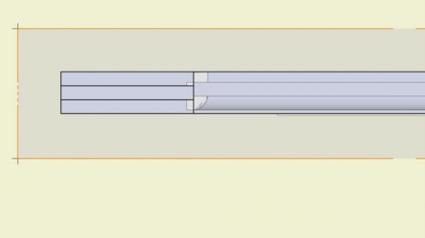
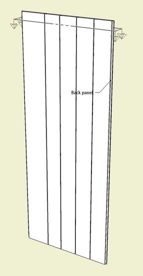
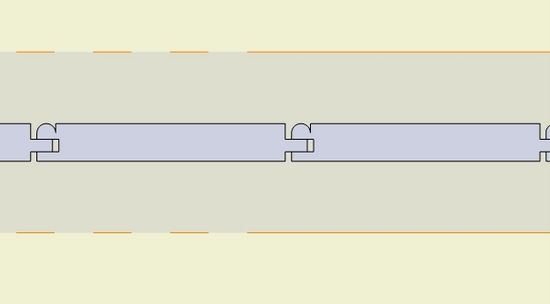
In this example, we have a back panel with tongue and groove construction.
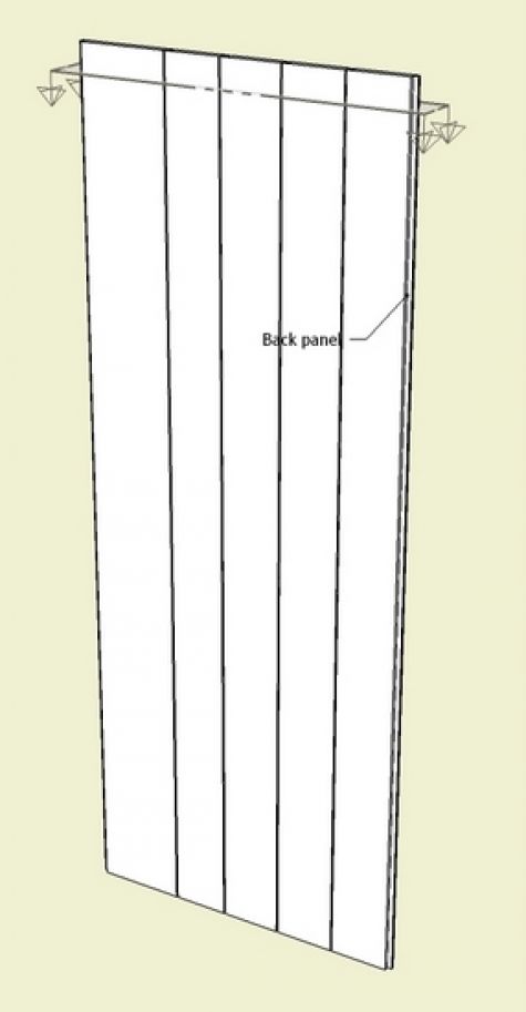
Again I set the cutting plane within the component definition and move it down a short distance from the upper surface where I initially placed the section.
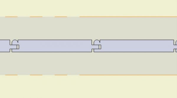
This view confirms proper connection of the tongue and groove and shows the expansion space.
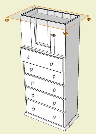
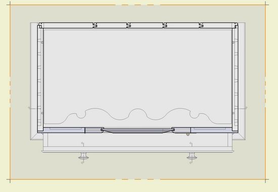
Sometimes I use the cross-section to verify overall construction integrity – I’ll use sections as an inspection tool. With the Move/Copy Tool, I can shift the cutting plane to any location and quickly have a look. I usually find funny things that are quickly identified and corrected.
Here is an example of using the section tool for inspection in the overall assembly.
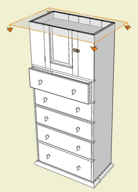
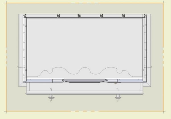
I’ve convinced myself that I should use cross-sections more often.
Tim




Log in or create an account to post a comment.
Sign up Log in