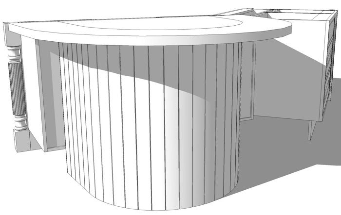
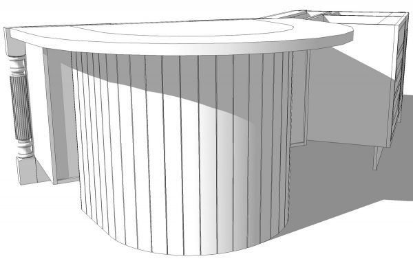
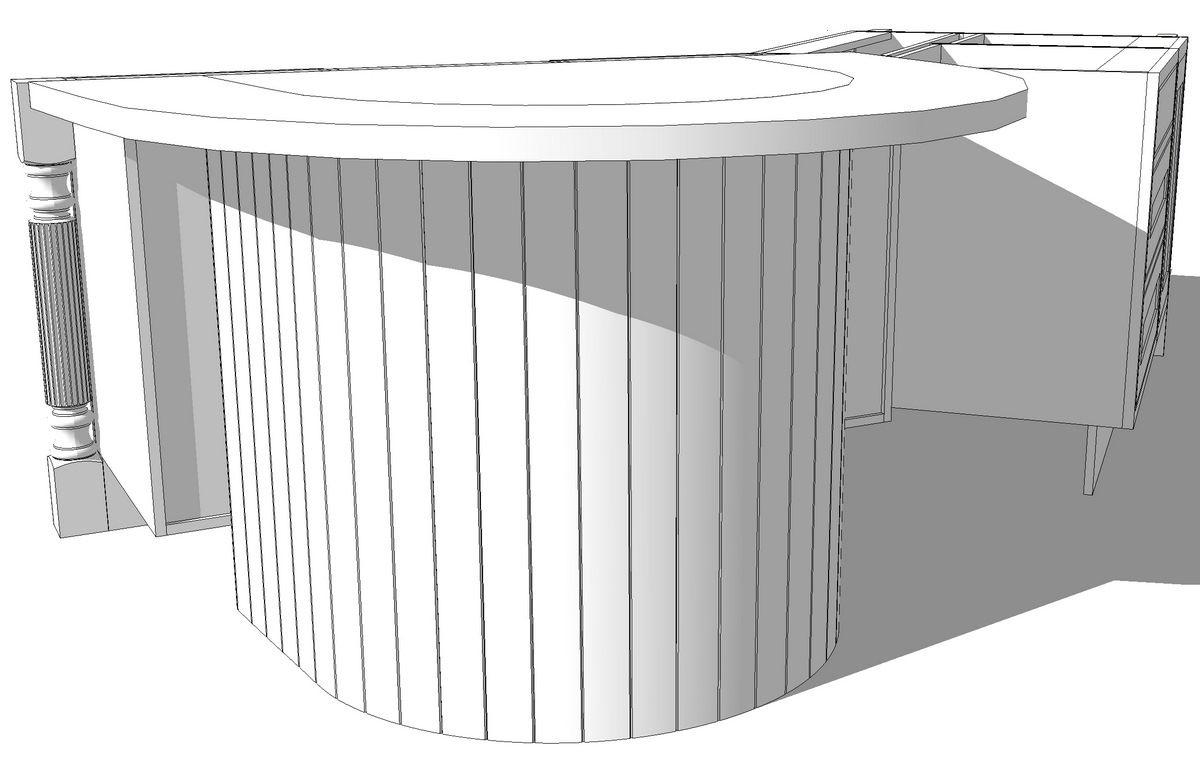
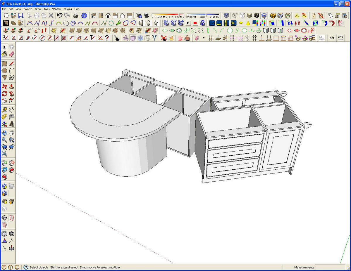
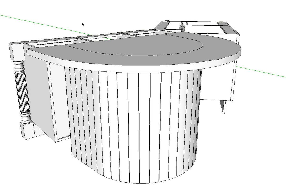
My friend Dermot emailed me today with a little puzzle. He’s working on an island design for a kitchen and he’ll end up rendering this image to show the client. His client wants to see bead board on one end and wrapped around the curved base under the bar something like I’ve got above. He sent me the model as shown below.
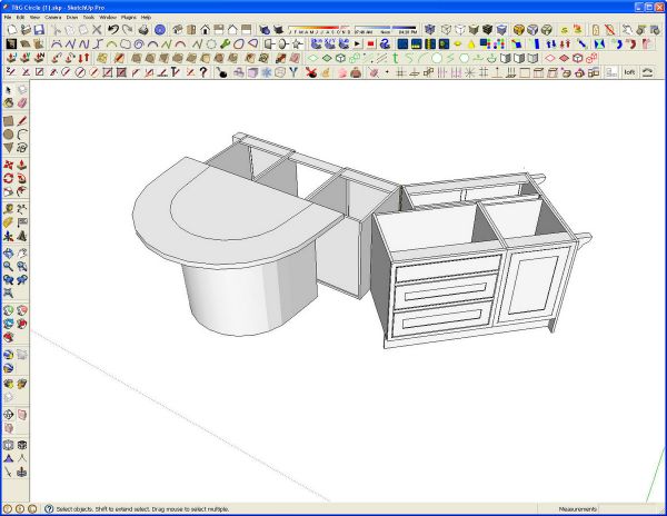
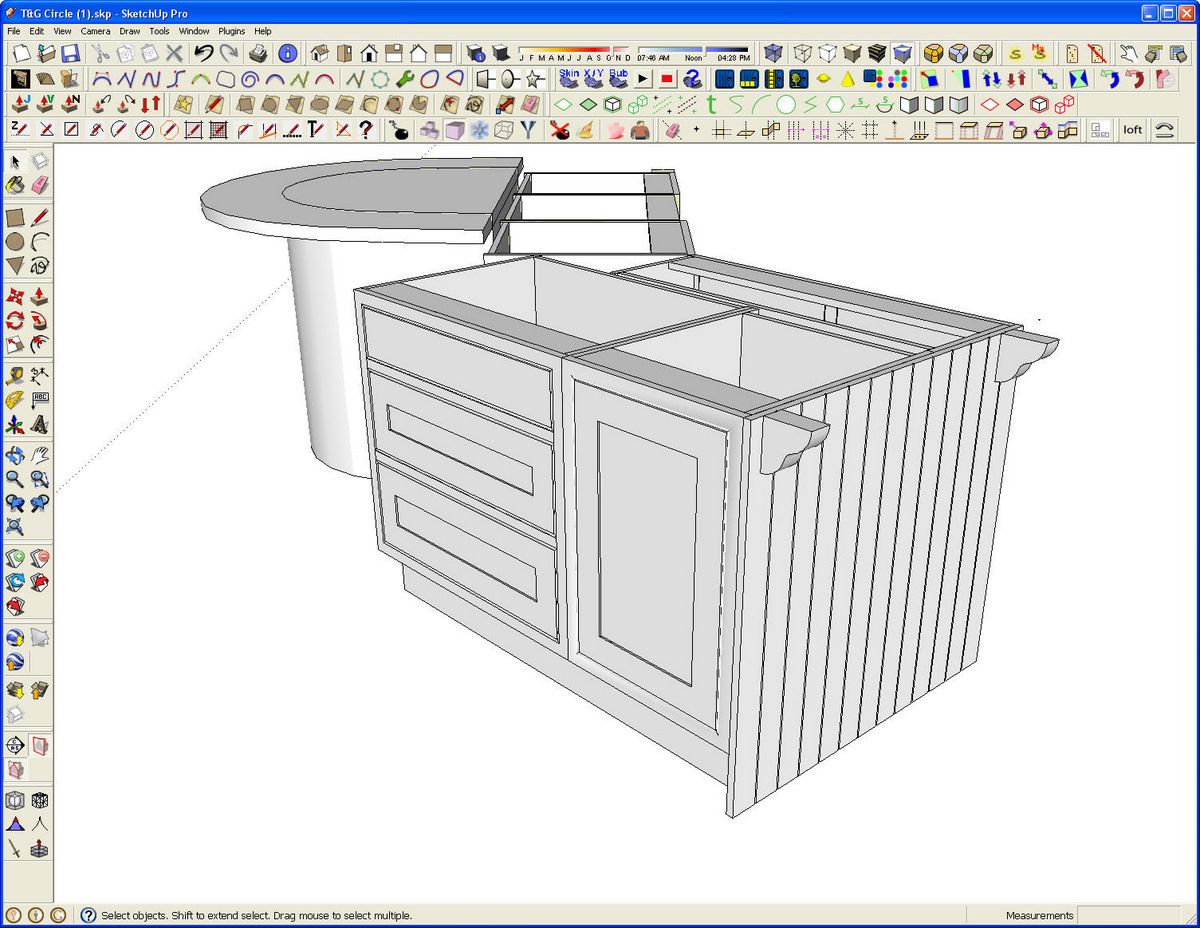
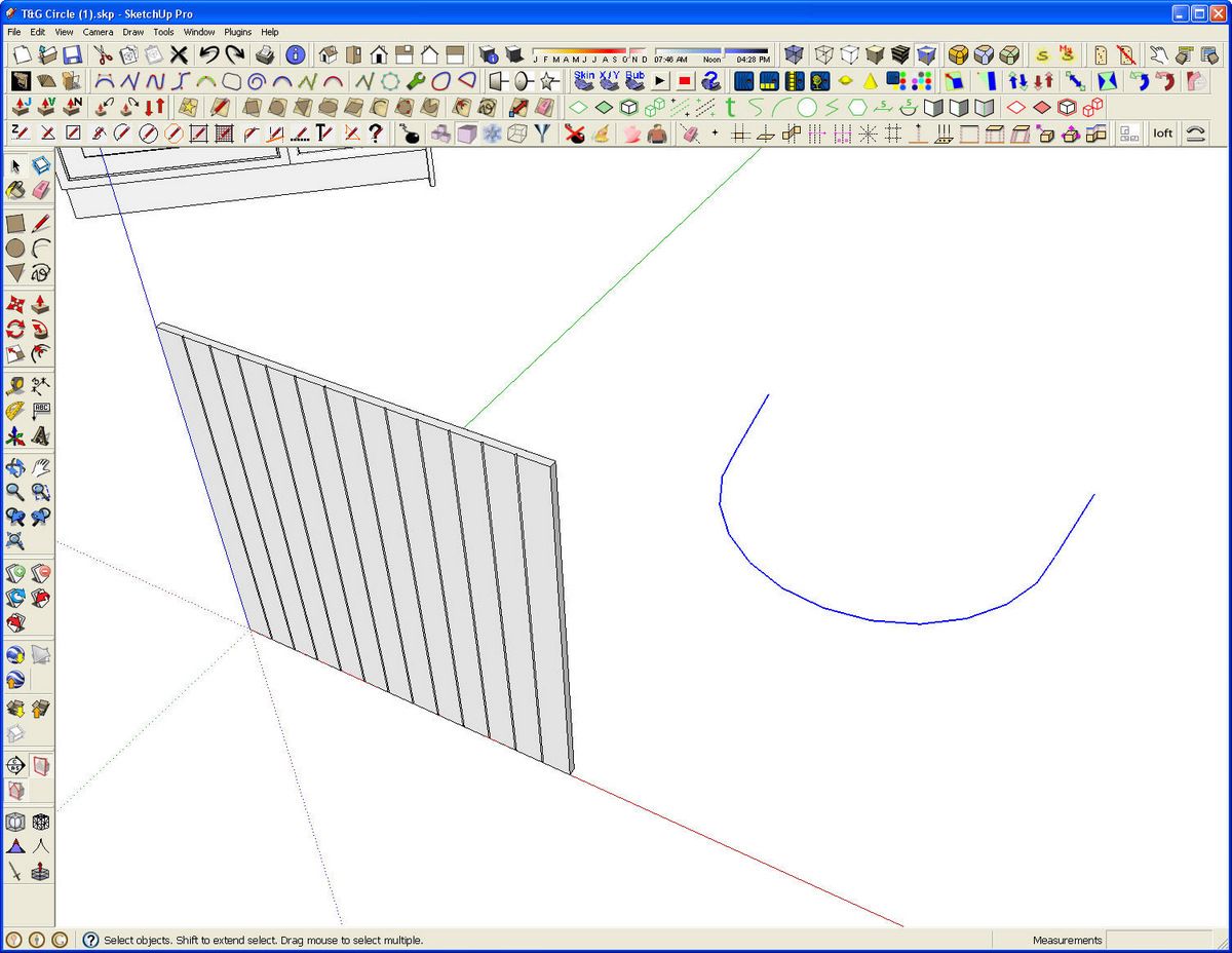
He had already drawn in the paneling at the end where it is flat.
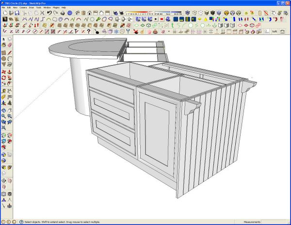
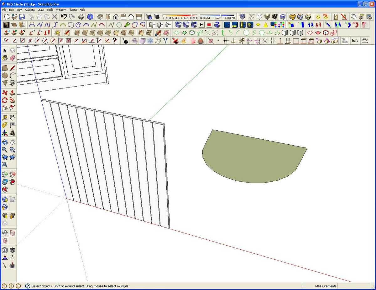
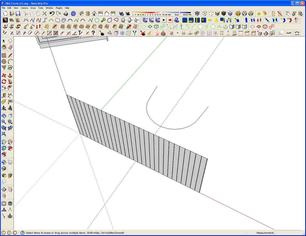
Since the end and the pedestal are to get the same material, I decided to use what he’d already drawn for the pedestal. The bead board is drawn as a single entity with the beads simplified to just V-grooves. In the final image it won’t be possible to tell that there aren’t beads drawn in and the V-grooves make for a lighter model. I copied (Ctrl+Move or Option+Move on Mac) the bead board over to the side and rotated it so that it is parallel to the red axis. I also copied the bottom of the pedestal Dermot had drawn.
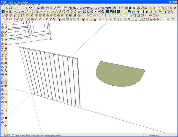
I don’t need the face or the straight edge at the back so I deleted those.
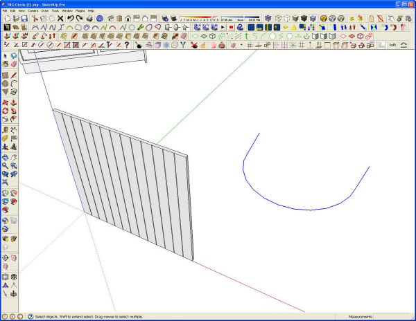
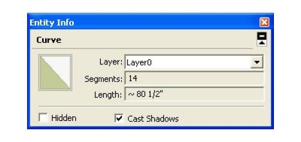
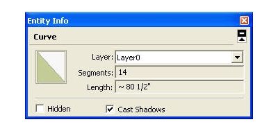
Next I selected the remainder of the pedestal shape and used the Weld plugin on it to make it behave as a single entity. While it was selected, I got the length of it by opening the Entity Info box. the exact length isn’t extremely critical here. I have Precision set to 1/64″ so I know that the 80-1/2″ length is pretty close to actual.
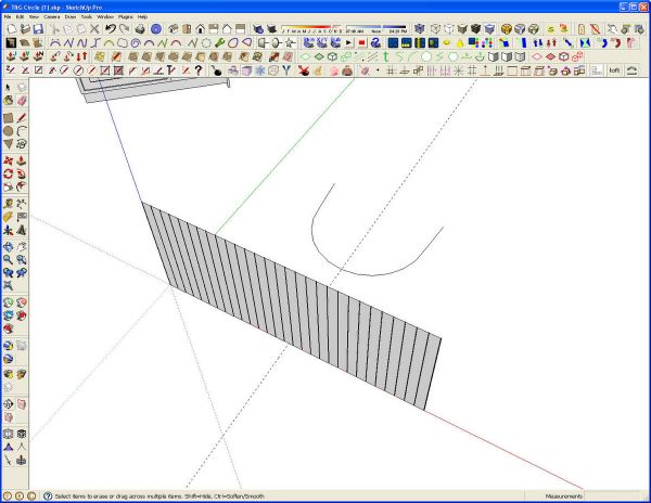
With that length in mind, I edited the bead board by cutting the end “boards” in half. Then I copied (again with Ctrl+Move) the bead board along the red axis the length of the first section and hit *2, Enter to make two copies. This makes the length of the bead board run more than the 80-1/2″ of the pedestal circumference. I marked of the 80-1/2 ” distance with a guideline drawn off the green axis. I also set one at the midpoint, 40-1/4″ in this case. I selected all of the bead board and moved it along the red axis so as to center one of the boards on the mid line. This was done by hovering with the Move tool to find the cyan-colored dot indicating the midpoint of the edge and then moving the whole thing over so that point coincides with the guideline on the midline. the beadboard was then trimmed to make it 80-1/2″ long. I also moved the curve behind it so it was centered on the midline, too. Before moving on, I deleted all of the bead board component except the front surface and then made a component of it.
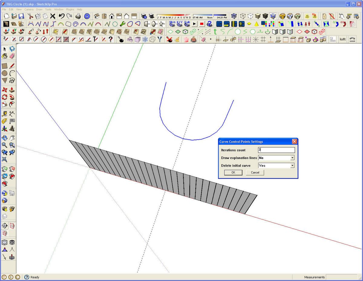
Since this model is going to be used for a rendering, I decided to make a smoother curve for the pedestal. This will increase file size but since this is for looks, I figure that’s alright. I used a fairly new plugin called Geometric Curve Smoothing on it. After selecting the curve, which needs to be welded if it isn’t a single entity, the plugin is activated by clicking on Smooth… in the Context menu. A dialog box pops up with a few options. I chose 3 for Iterations and left the other options alone.
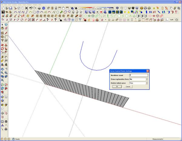
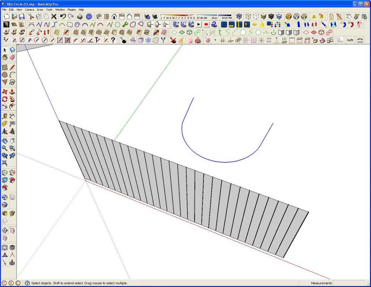
The next step involves using the Shape Bender plugin which I’ve mentioned before. For the example I’ve moved the bead board component up a couple inches. Then I drew a straight line 80-1/2″ long on the red axis immediately under the component. It’s probably difficult to see in the screen grab but it is there.
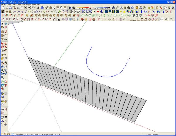
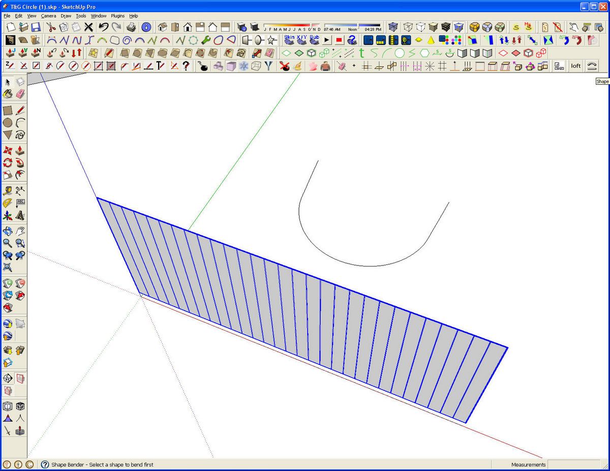
Next I selected the bead component and then activated the shape Bender plugin by clicking on its toolbar icon. The tool is just above the right corner of the drawing window on my screen.
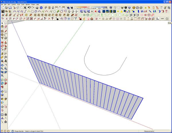
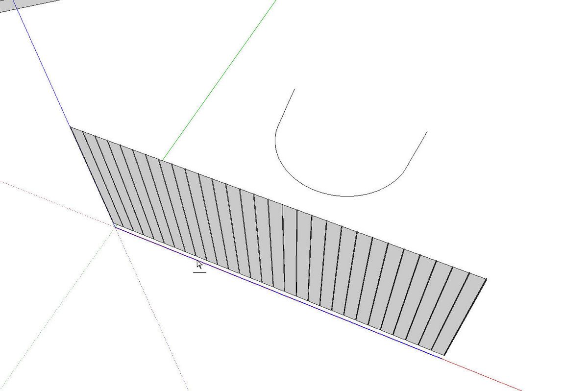
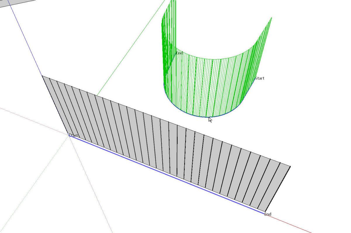
The tool shows an arrow with a line under it. there’s a prompt at the left bottom corner of the screen indicating that the plugin wants a straight line selected. I hover over the line on the red axis. when the line is highlighted, I click on it.
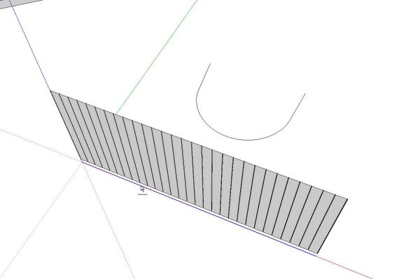
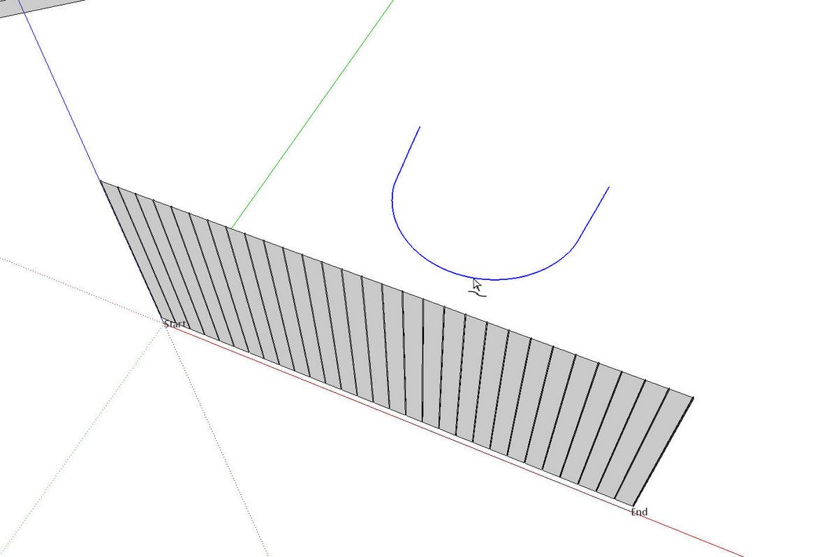
The cursor changes to an arrow with a S-curve below it. This is the indicator that the plugin wants a curve to be selected. I clicked on the curve in the background. Note that after clicking on the straight line there.s notes indicating the start and end of the line.
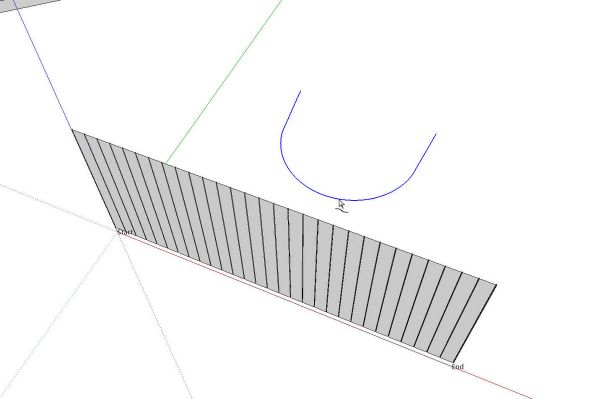
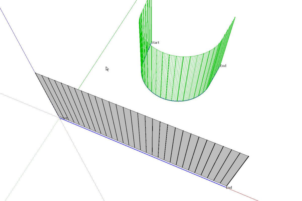
The plugin then draws a temporary wireframe view of the bent component. It also adds start and end labels for the curve. Ideally you want the start and end of the line and curve to correspond to each other. The direction in which they are drawn will impact where the labels are placed. If the labels are crossed after the second click, press the up arrow key to reverse them.
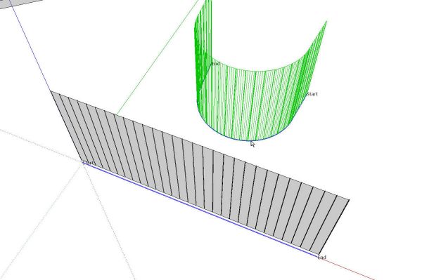
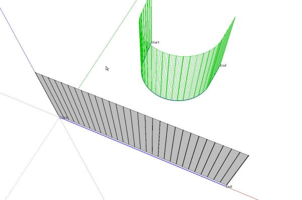
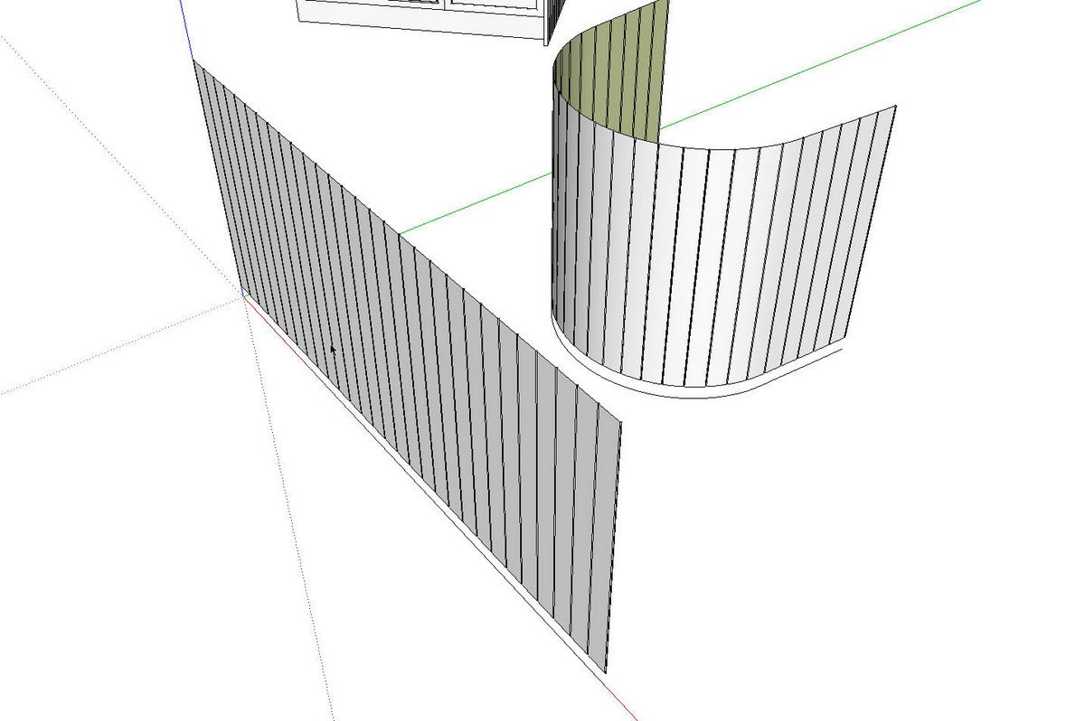
Then I hit Enter and I have a bent version of the flat bead board component.
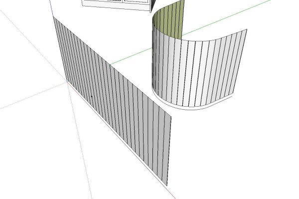
I opened the new component and added a couple of lines across the opening to fill in the faces top, back and bottom and then I moved it into place. Push/Pull on the original pedestal made quick work of getting rid of it leaving just the bead board pedestal in its place.

This whole things seems like a long process but it actually goes quite rapidly when you’ve got the plugins loaded and ready to go. you could make a respectable dentil molding around a curved path using a similar method. Keep in mind the Shape Bender plugin only works with the straight component and straight line parallel to the red axis. This plugin also requires ProgressBar.rb which you may or may not have already.
Give it a try and see what you can come up with.
Thanks to Dermot for letting me play with his model and use it for this blog entry.
You can get the plugins I used here by clicking on the links in the text. You may need to register for some of them but they are free.



Comments
Dave,
I've noticed a curious thing. If I'm not logged on the images in the article don't show.
Another thing is Shape Bender.
I followed the link and, for the life of me, can't download it.
Where's the download link?
By the way, nice tut.
d
Don,
Thank you. The link I posted goes to the Sketchucation Forum site. You need to be registered there to access downloads. The file will be at the end of the first post in the thread I linked to.
As to the images posted with blog entries, they're posted on the FWW servers. I'm not sure about the log in requirements to see the images. I'm always logged in when I'm working on the blog.
Dave
Log in or create an account to post a comment.
Sign up Log in