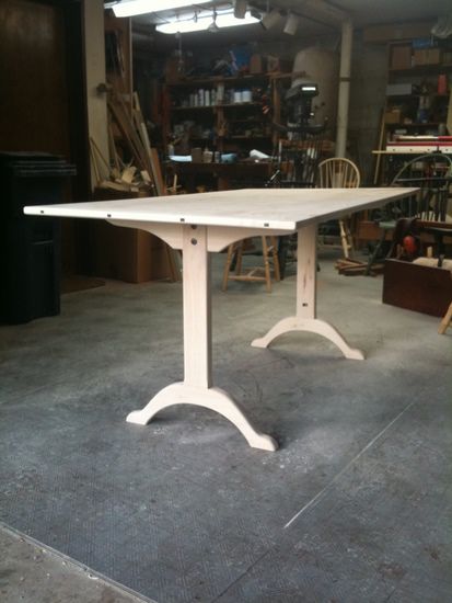
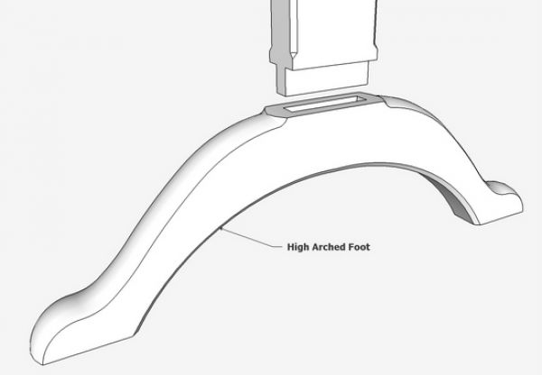
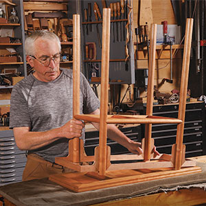
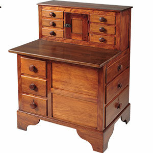
Last week I showed the procedure I used to make the breadboard on a Shaker Table. Using that same table, I will demonstrate a method for making and shaping the high-arched foot. The making of the foot is quite straightforward, but its shaping is quite another matter. When molding or shaping a rectilinear component, the exercise is rather easy using the Push/Pull Tool. However, in this case, we are molding an arched component, and the procedure is perhaps 10 times harder.
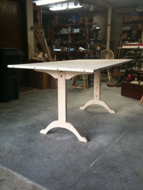
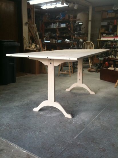
I’m constructing the table now in Silver Maple……
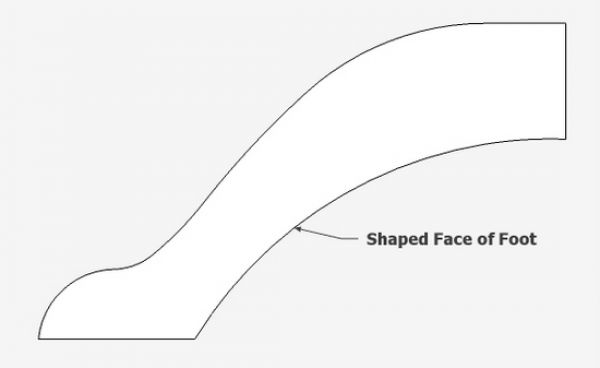
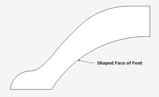
Step 1: The face of the shaped foot is created with the Arc and Line Tools. It is best to work with one-half of the foot, since it is symmetrical. This saves a lot of time.
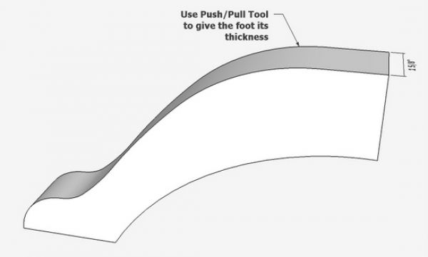
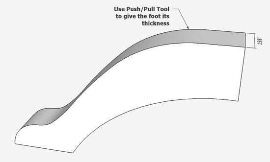
Step 2: Using the Push/Pull Tool give the shape a thickness – in this case 1 5/8-in.
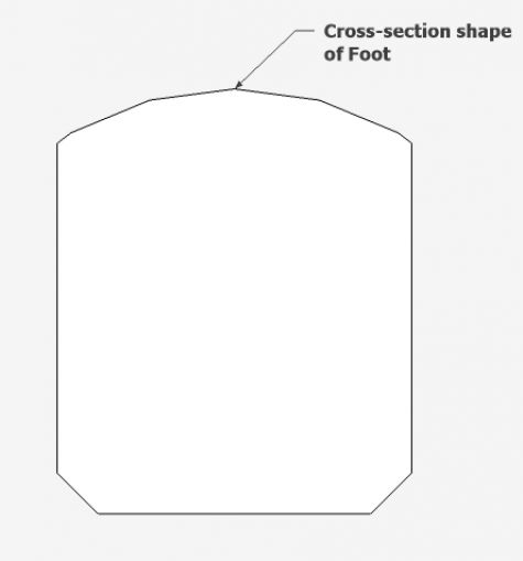
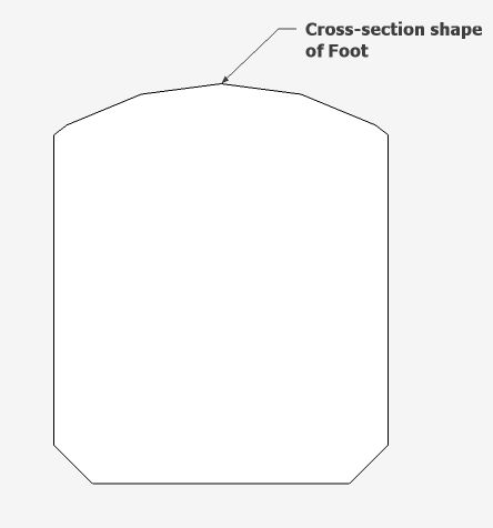
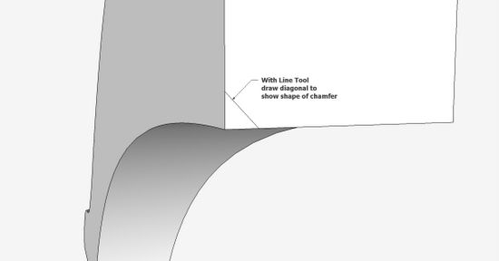
Step 3: The foot is rounded on the top surface. However, this rounding stops short of the flat area where the leg is mortised in. On the bottom arch of the foot, there is a slight chamfer. Here is the cross-section view of the foot.
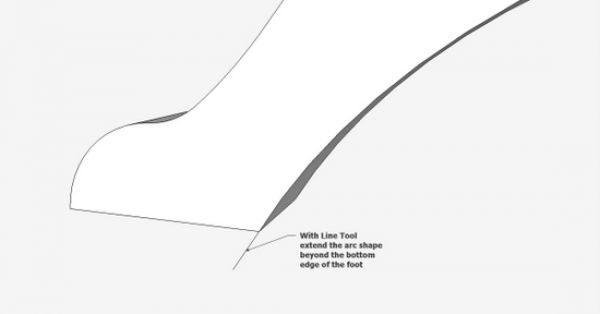
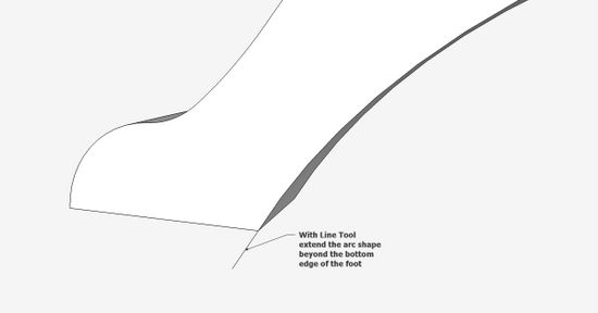
Step 4: To do the chamfer on the lower arched edge, we need to extend the arch shape with a short straight line. This extension will be part of the Follow me path, so that the shaped chamfer continues beyond the end of the foot.
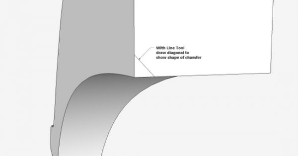
Step 5: In this step, make the chamfer shape on the upper flat face of the foot.
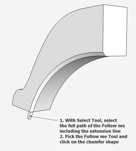
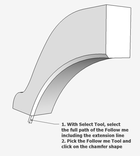
Step 6: Execute the Follow me, by first selecting the path including the line extension at the lower edge. Pick the Follow me Tool and click on the chamfer face. Note that the shape moves beyond the lower end, so we can get a clean finish for the chamfer.
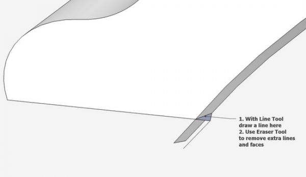
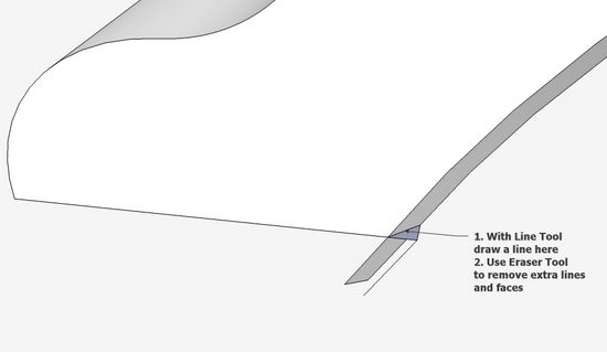
Step 7: We need to do some clean-up work at the lower extension. This can be done by doing an Intersection, however it is easier in this case to simply draw a line as shown in the picture below. Then clean-up the waste with the Eraser Tool.
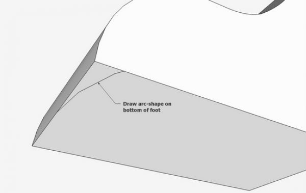
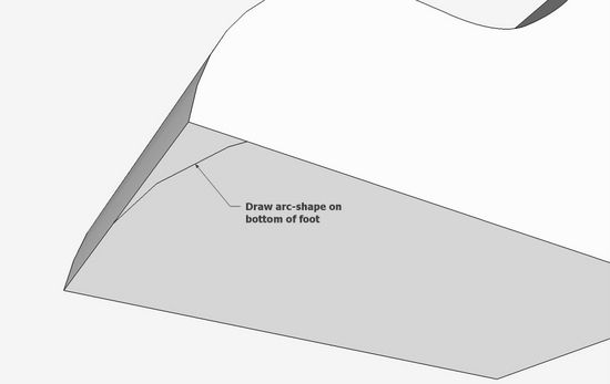
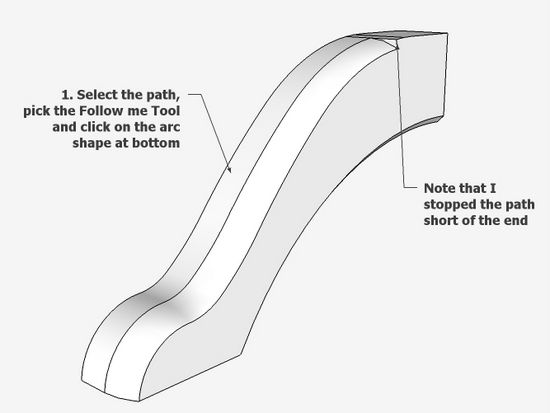
Step 8: Now to shape the upper surface of the foot. With the Circle or Arc Tool, draw the arc shape for the top surface (only one half of the arc from the midpoint).
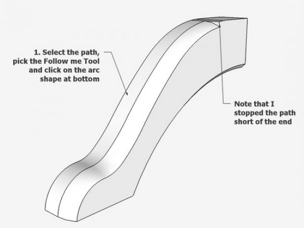
Step 9: There is a center portion or the foot which is not shaped. This is where the leg mortises into the foot. So the path for the Follow Me is shortened about 3/4-in. shy of the edge of the leg. Select the path and execute the Follow Me.
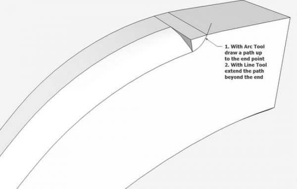
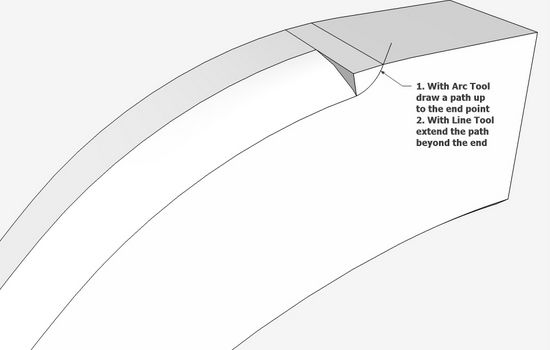
Step 10: We need to transition the abrupt end of the follow me so it is nicely faired to the top surface. Place an arc path for this transition and again provide a line extension so that the extruded shape goes beyond the top edge of the foot.
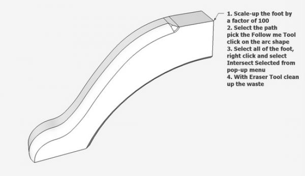
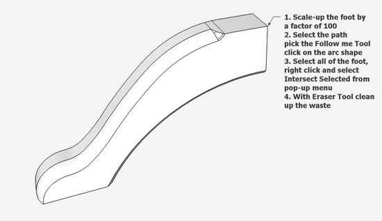
Step 11: Since this Follow Me is very small and at a sharp radius, we need to scale-up the component by 100 times. Then select the path, and execute the Follow Me. There is quite a tedious erasure of waste lines and faces.
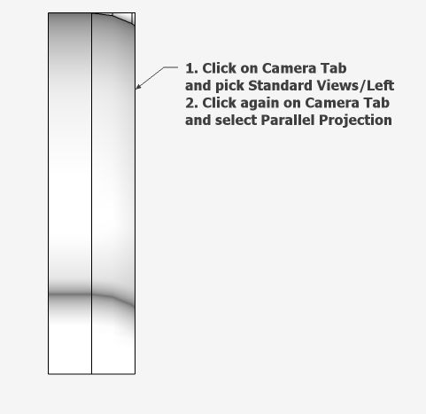
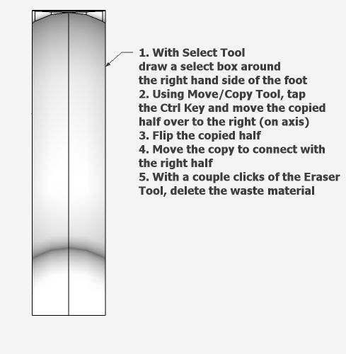
Step 12: We’ve only rounded one side of the foot. Rather than going through the above procedure again for the other side, it is much easier to simply copy and flip the existing shaped edges.
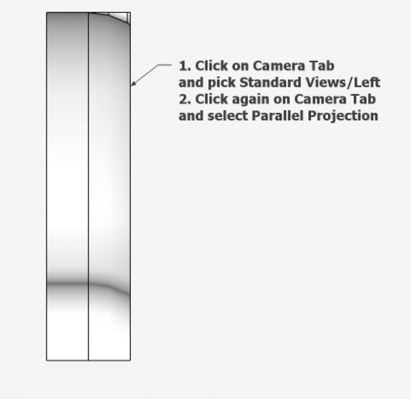
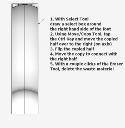
Step 13: After positioning the foot as shown above, select the rounded half, copy it to the right, flip it, then move back over to replace the other half of the foot.
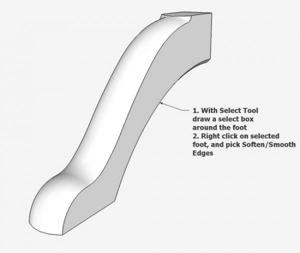
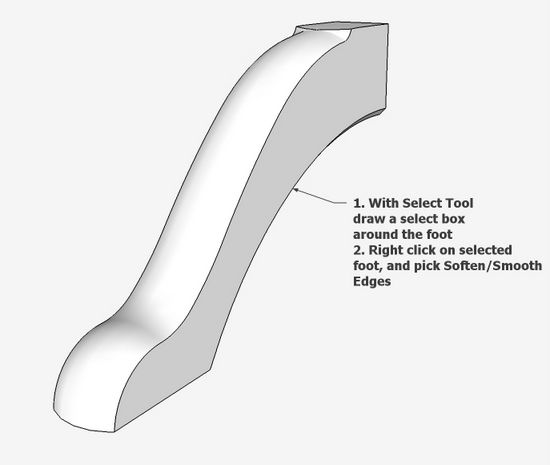
Step 14: In this step we use the Soften/Smooth function to remove the hard lines.
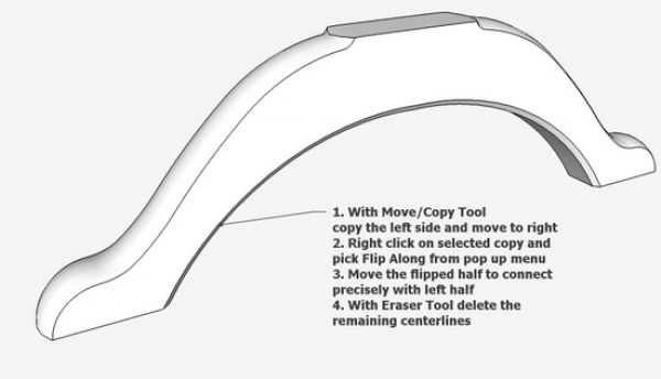
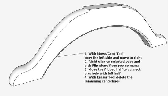
Step 15: Copy the existing half, and move over to the right. Flip the copied half and reconnect to the original half. Use the Eraser Tool to delete the line at the middle joint.
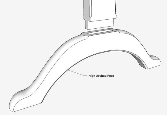
Step 16: As a final step, cut the mortise for the leg in the top surface of the foot.
I have to admit, that I can make these feet in the shop faster than it takes me to produce this blog entry. However, in doing the modeling, I’m accurate and fast in the shop.




Comments
Hi Tim,
Many thanks for all your and David's contributions. They are a great help to those of us who are struggling to learn and become useful with Sketchup. Please may I wish you both a great Christmas & best wishes for next year.
Log in or create an account to post a comment.
Sign up Log in