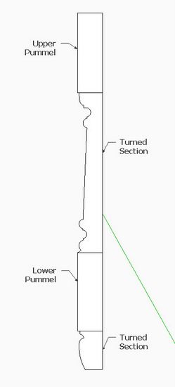
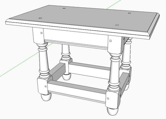
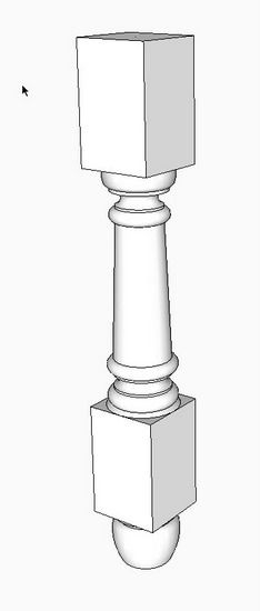
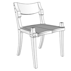
Often furniture with turned legs and stretchers have pummels or square sections of the turning. Both Dave and I have previously shown methods for handling this complexity. A reader recently asked to see the process again, so here is how I do it using the following model of a 17th C. Connecticut Stool.
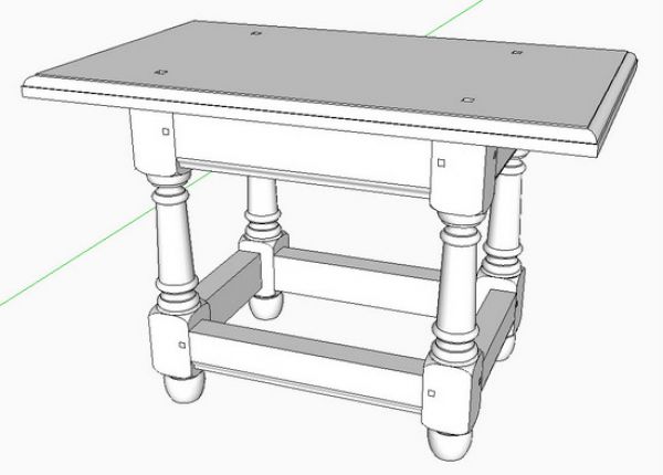
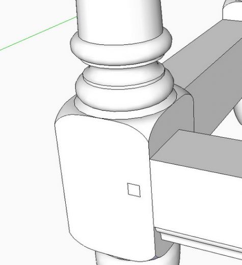
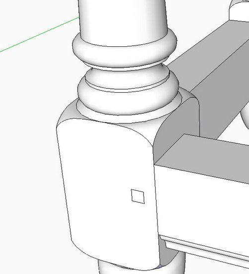
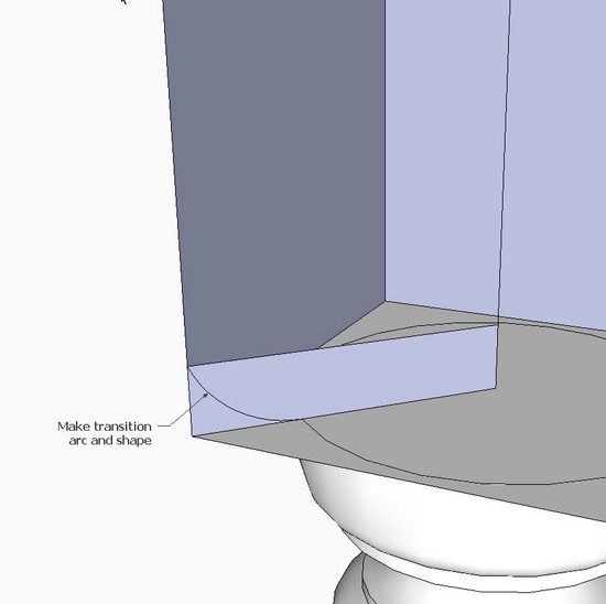
Within the turning of each leg there are two square sections (sometimes called pummels) which support the mortise & tenon connections from the rails and skirts. The challenge, both in SketchUp and in actual lathe work, is making the transition from the round portion to the square shape. Sometimes this transition is in an ogee shape, but in this case it is a simple rounded arc transition. See close-up of transition in the following illustration.
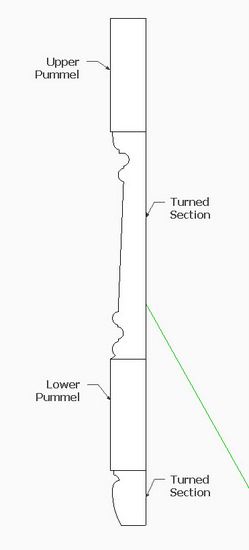
Step 1: Create the flat face shape of the turned leg including the square or pummel sections.
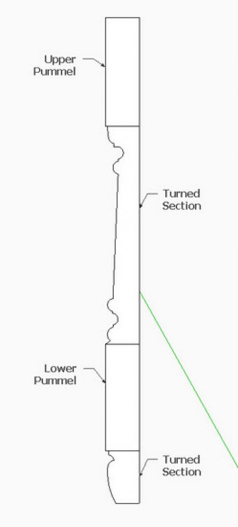
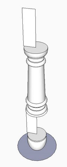
Step 2: Turn (in SketchUp use Follow Me Tool) to create the turned sections of the leg.
Note the rectangular shapes of the pummel sections which are still only flat faces.
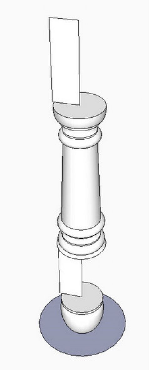
Step 3: Using the Push/Pull Tool, change the rectangular faces into full 3D pummels.
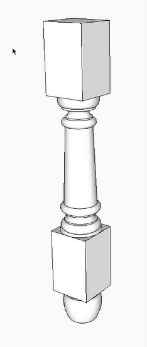
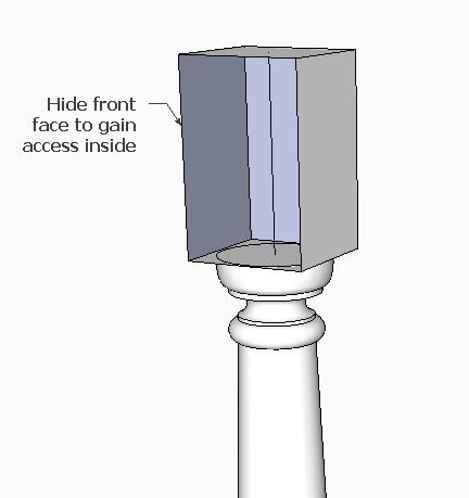
Step 4: Right click on the front face of the pummel, and select Hide from the pop-up menu. This will allow viewing access into the inside of the pummel.
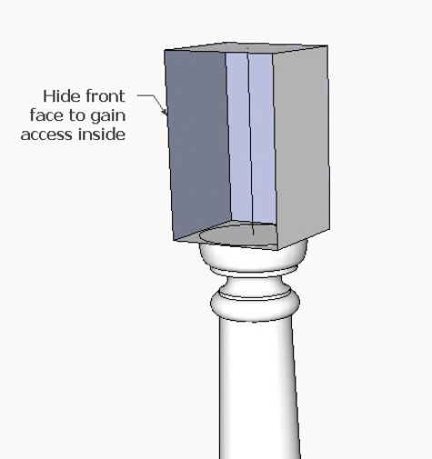
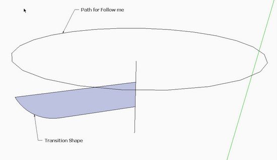
Step 5: Create a diagonal rectangle from the center of the pummel, then with Arc Tool, draw the transition shape.
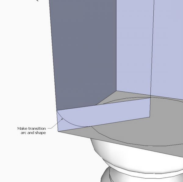
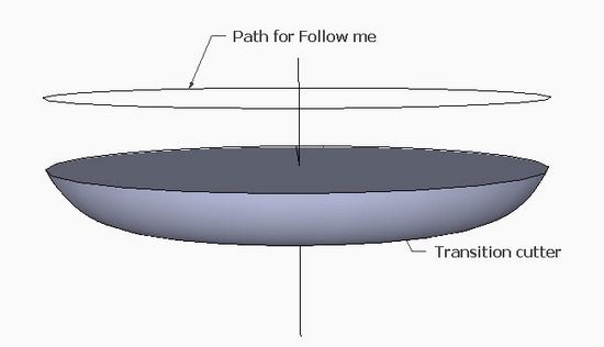
Step 6: Use the Move/Copy Tool to move the transition shape away from the leg. Set up for turning this shape with the Follow Me Tool.
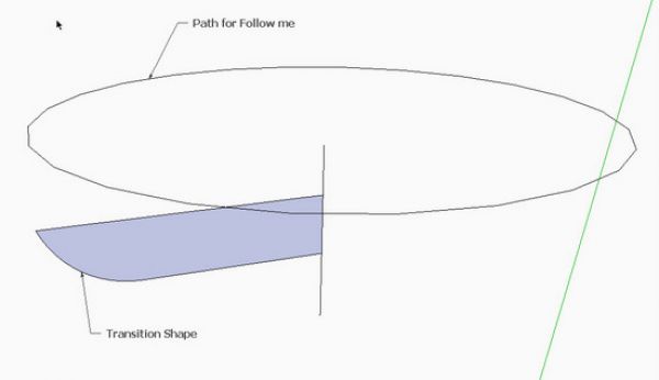
Step 7: Execute the Follow Me resulting in the Transition Cutter as shown below.
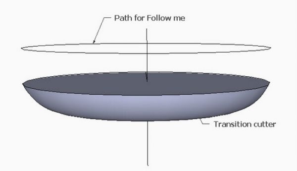
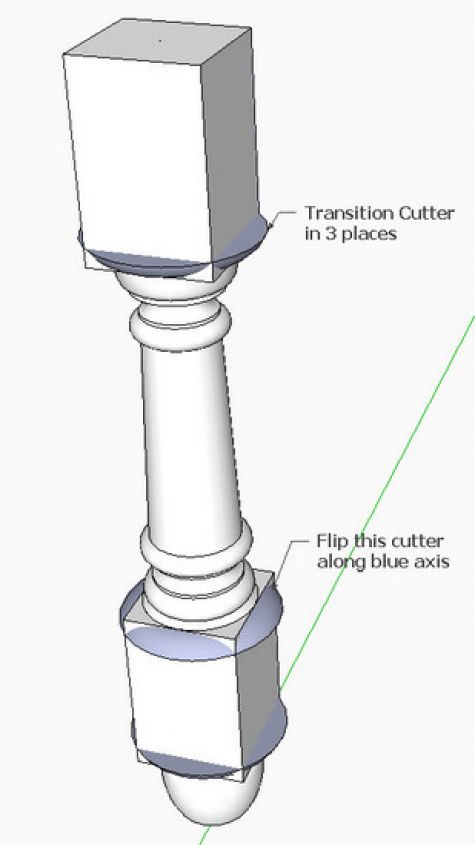
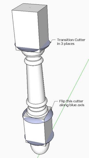
Step 8: With the Move/Copy Tool, precisely position copies of the transition cutter into the three locations on the leg turning. The middle cutter must be flipped along the blue axis for proper orientation.
At this point I explode any components or groups, select all of the leg including the transition cutters, and scale up the size by a factor of 10 with the Scale Tool.
Step 9: Right click on the selected leg and pick Intersect with Selected from the pop-up menu.
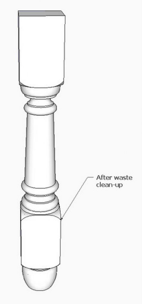
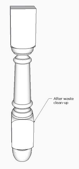
Step 10: Use the Eraser Tool to clean-up waste. Select the entire leg, right click and select Make Component.
Select the leg component and use Scale Tool with factor of 0.10 to bring it back to full size.
Tim Killen
http://killenwood.com




Comments
I recently modeled a bed in the Thomas Sheraton style where the square to round section creates an urn shape on the flat. I looked for a straightforward way to do it but couldn’t find one. I ended up tracing the flat from the existing bed with a crayon onto paper, scanning that into the computer, importing it in to SketchUp, tracing the shape with lines and curves, then scaling circles along a cylinder to intersect that line.
It worked, but it seemed like there must have been a simpler way. Any suggestions? It seemed like there should have been some way to project lines around curved arcs of various radiuses.
To SchreiberBike: I believe the urn-like shape on the flat will occur when you change the transition shape to an ogee. I do this the same way as shown here, but in Step 5, I change the shape to an ogee (reverse arcs). Also you can perhaps increase the depth of the transition.
Tim
Thank you Tim,
I will put this to good use.
Frank
Tim
Following this tutorial brought home to me the importance of building models in-situ ,which you and Dave Richards keep mentioning . In certain views things can look fine but looked at from another direction I can see I am way out .
In step 8 I had great difficulty positioning the transition cutter precisely both vertically and horizontally on the newel post centre line. Locating a pickup point on the turned transition cutter and matching this with a position point on the post I found difficult. How do you get over this?
On the positive side it is exciting seeing profile turn into a real 3 D object , for me this is one of the joys of SketchUp in comparison to other 3d Cad programs.
A further important element of the tutorials on the site is being able to use what I learn and apply to other situations in my SketchUp modelling for which I am very grateful to you and Dave .
Thanks
Jonas Mac
To JonasMac: Thank you so much for your encouraging comments. Also, it is heartening to hear that readers actually try the exercises, and report on the experience.
Your issue with connecting the cutter precisely..... good comment. I always do my turnings with a centerline as part of the component. See in Step 8 above that the cutter has a centerline. This always provides a precise connection point. With the Move/Copy Tool I can grab the intersection of the centerline with the top face of the cutter. Then I can move the cutter to precisely connect with the centerline intersection of the turned leg.
In making Windsor chair models, I would be lost without centerlines in all the spindles, legs, and stretchers.
Tim
Great tutorial, Thanks!
Haven't tried it (just read it) yet but will do and let you know the results.
Tim
Thanks for the reply. A few comments/feedback on my experience with the tutorial & SketchUp first and then a question.
Comments
I find there is a huge difference between just reading through the illustrated sequence of steps in a tutorial and actually opening up SketchUp to try and recreate the tutorial illustrations/steps on my own screen. Apart from getting practice using SketchUp you are forced to think of ways round the problem when you screw up , often I remember a move used in a previous tutorial and maybe try that to get over my immediate difficulty .
The 9 steps illustrated in the above pummel creation look reasonable , but on my screen getting the pieces to line up , concentric on a centreline both on plan and elevation is another matter . As with my efforts on Dave Richard's original Fern Stand tutorial a few posts back , where I could create the individual pieces , legs, rails etc , but getting the pieces to fit ( even with Dave in my earpiece stressing the importance of constructing the members in place ) I still find difficult .
Question
The centreline illustrated in Steps 4 to 7 of the above tutorial , are these embedded in components , at what stage do you introduce them ?. Would you normally have a centreline embedded in the finished piece i.e after completion of Step 10 ?
Jonas Mac
To JonasMac: Thank you for the feedback. I wish it weren't so frustrating, but I remember when it was tough for me, so I understand the issue.
On your question..... I introduce a centerline into my turned components at the very beginning. I usually have centerlines extending beyond the turning and these are indeed within the component definition. However, in steps 4 and 5 above you see the centerline but in this case it is not extending beyond the end faces of the leg.
Without centerlines, I would have a very difficult time connecting the turned components.
Perhaps I will do an entry on precise positioning....
Tim
Log in or create an account to post a comment.
Sign up Log in