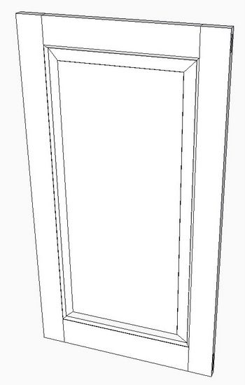
Last week I showed my method of modeling the frame for a small cupboard paneled door. The frame consisted of the stiles and rails fastened with through mortise and tenon joints. It is a classic design with a thumbnail molding on the inner edges of the stiles and rails. These required a miter joint at the inner corners.
This week I’ll complete the paneled door by making the bevel-edged panel. Although some door panels have a beveled edge on one side only, this panel is a full thickness of 3/4-in. with bevels on both sides.
Typical of SketchUp modeling, there are a number of ways of making this panel. I’ll show you one way which works for me.
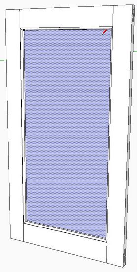
Start the panel by drawing a face which just fits within the inner boundary of the stile/rail frame. At this point the face does not include the protrusion into the 1/4-in. wide grooves. Make this face a component.
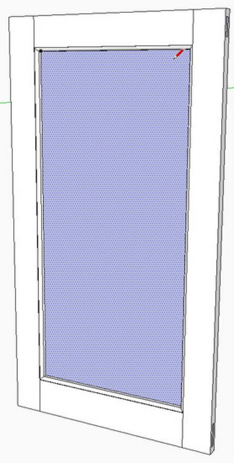
Make a copy of this component (face only), and move over to the side of the frame. Using the Push/Pull Tool, give the face of the panel a thickness of 1/4-in. This is a temporary thickness as it eventually will be 3/4-in. thick.
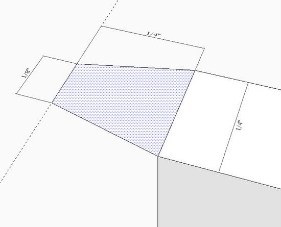
On the upper corner of the 1/4-in. panel, layout a small trapezoid shape that will protrude into the groove. I like to have a 1/8-in. width on the very end of the beveled edge. Also, I’m showing a 1/4-in. protrusion (this is less than the depth of the groove to allow for seasonal expansion).
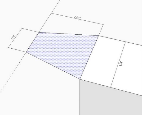
Increase the panel thickness to 3/4-in. by pulling out each face an additional 1/4-in.
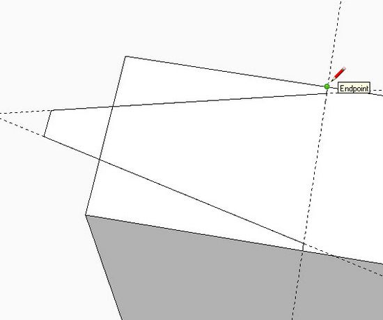
Draw guidelines to help with the continuation of the bevel shape. This is easily done by double clicking the Tape Measure Tool on each of the two angled edges of the trapezoid. Use the Line Tool to draw over the guide lines to finish the shape. We’re preparing a shape in this step that can be used in a Follow Me process around the edge of the panel. As you can see at the Line Tool icon below, I like a small vertical recess at the fat portion of the bevel.
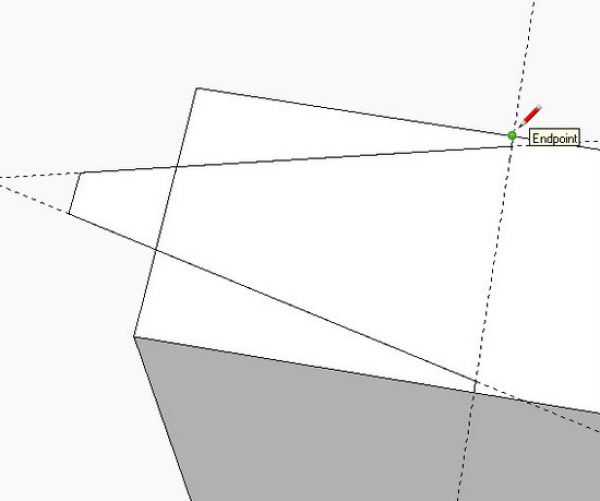
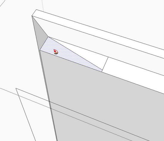
Create a path for the Follow Me. You will require three separate executions of the Follow Me, since there are three separate small faces shown above.
Select the path, pick the Follow Me Tool and click over one of the three faces. The figure below shows the results from two out of the three Follow Me’s.
After the Follow Me’s, there will be a few extra lines on the surface of the bevels. Use the Eraser Tool to remove these.
This ends the creation of components for making the paneled door. If you made the initial flat face within the frame a component, then the completed panel will be perfectly positioned within the frame’s grooves.
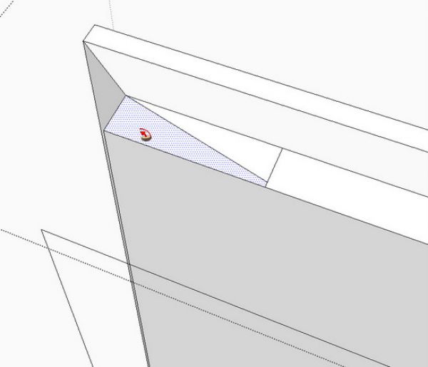
If your initial face was not made a component, then use this process to accurately place the door within the frame. It may require three steps for each of the three axes alignments. Use the “midpoint” inferences to help with the alignments. For example, to align the panel with the center of the grooves, click the Move/Copy Tool on the midpoint of the edge of the panel. Start the move, tap the left arrow key to force the move along the green axis. Slide the mouse along the edge of the frame until reaching the midpoint inference and end the move. This same procedure can be used to center along the other two axes.
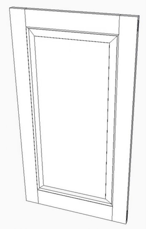
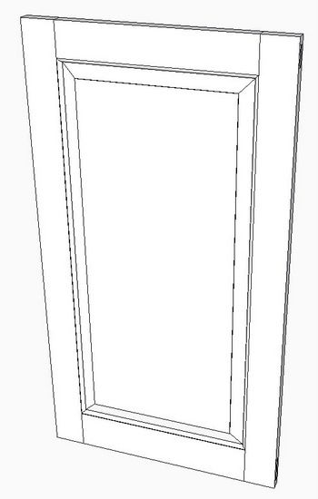
Here is the completed door panel.





Log in or create an account to post a comment.
Sign up Log in