In using the term “quirk” I’m not referring to an architectural term – a division of a molding. Rather I’m referring to a “peculiarity of action”. A reader asked me why SketchUp was not doing as expected, so I’m preparing this blog entry to advise others that may have run into it.
I am sure Google would not use the term quirk; they would confidently explain why this occurrence is quite normal and expected, but here goes.
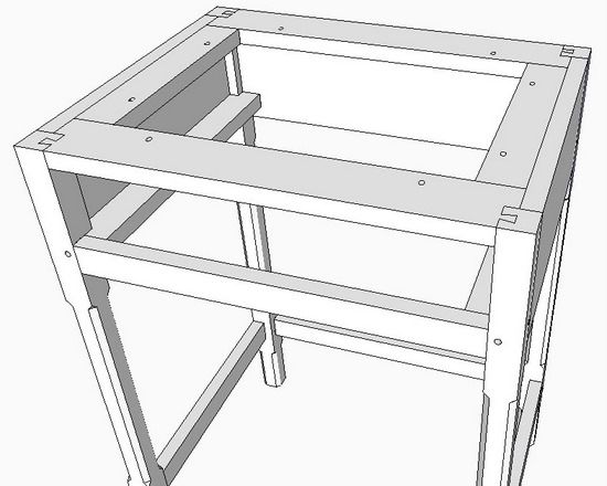
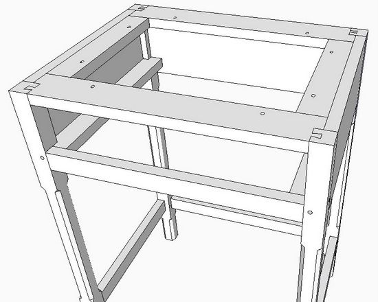
In the table shown below, there is a dovetailed framework attached to the top of the legs and is used to fasten the top piece with wood screws. Since the top expands and contracts cross-grain with the weather, it is important to allow some movement in the top. Therefore, screw slots (elongated holes) are used for the fastening of the top.
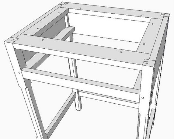
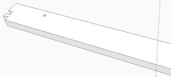
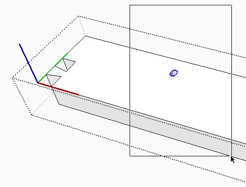
Here is a view of a frame part with a screw slot in one end. Say you now want to copy the existing slot to the other end of the frame part.
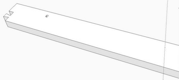
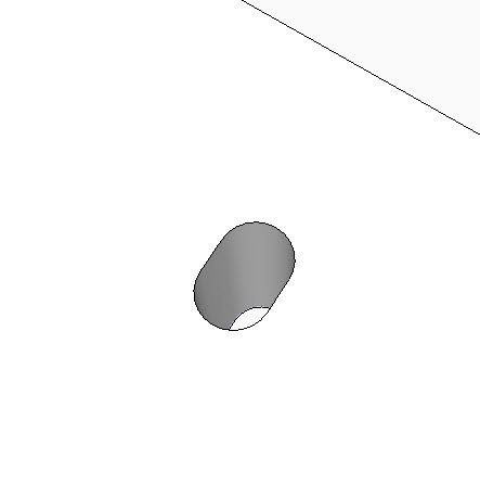
Here is a close-up view of the slot which was created with the Circle and Line Tools, then Push/Pull through to create the hole. Since making this slot takes a few tools and steps, it is preferred to copy it rather than make from scratch each time.
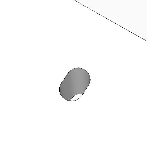
To copy the slot, use the Select Tool with a left-to-right select box
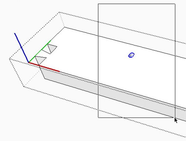
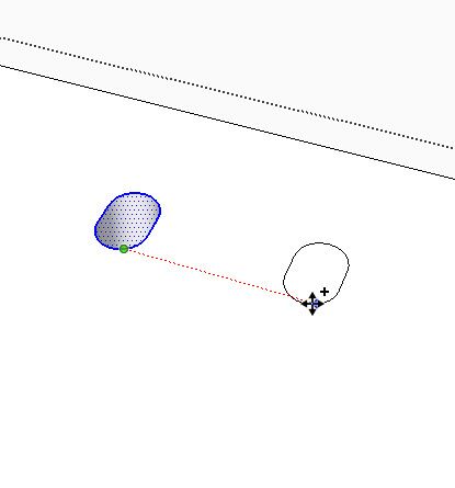
With the Move/Copy Tool move the slot down the red axis. Rather than move it where it belongs at the other end of the frame piece, I will stop it close for ease of illustration.
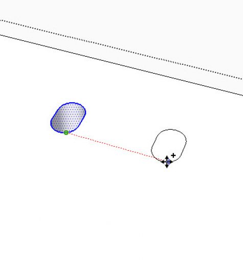
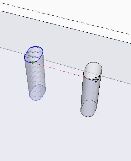
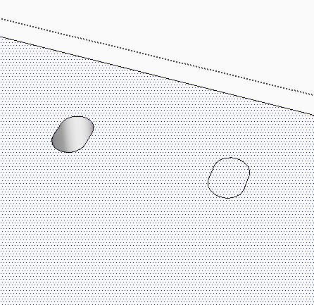
Here’s what it looks like in X-ray.
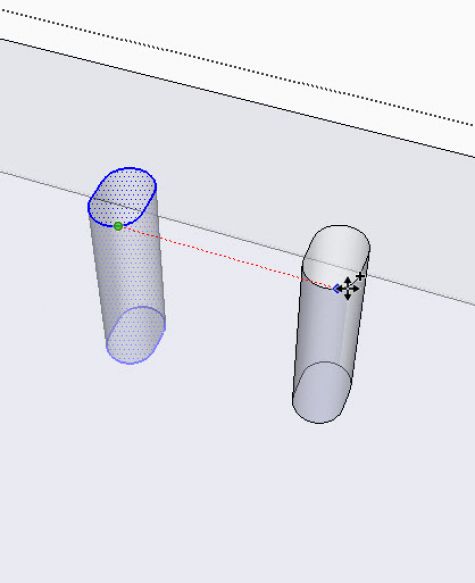
Now here is where the “quirk” shows up. Note that the surface of the frame part (which I’ve selected so it has the blue dotted look), covers over the surface of the slot. If you try to delete the slot surface, you will instead delete the whole face of the frame part.
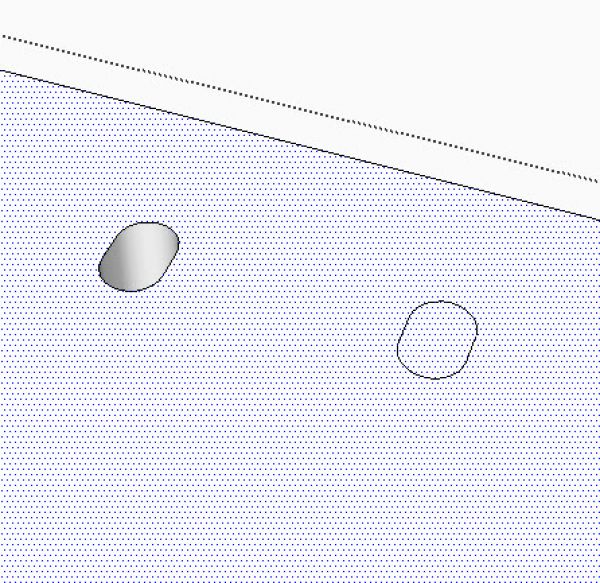
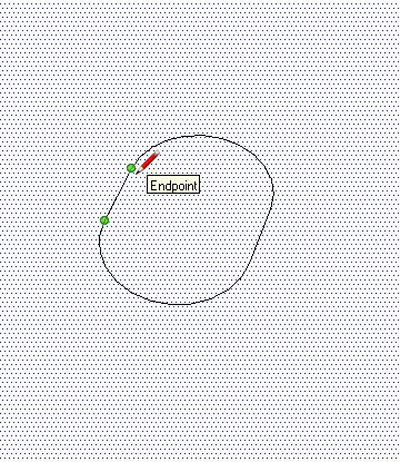
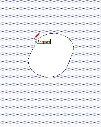
To make the new slot cut into the frame face, you need to use the Line Tool to draw over one small segment of the slot perimeter. It doesn’t matter which segment of the perimeter you trace over, but make sure you zoom in very close to pick “endpoints”. SketchUp will tell you when you are clicking on an endpoint. See the flag below. You can also pick a line segment on the arc – it doesn’t matter.
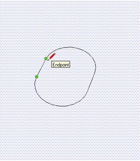
After clicking the endpoint with the Line Tool, immediately the whole perimeter of the slot cuts into (or intersects with) the frame face. You will see the blue dotted selected face disappear from the slot’s cover.
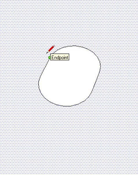
Now you can select the cover of the slot, and hit the Delete Key, or right click and Erase. This will give you the hole in the top surface. However, you will need to do the same thing on the bottom surface.


Comments
I've found that a hole that doesn't go all of the way through a piece doesn't suffer from this quirk, so that's the way I usually handle it: I draw the partial-depth hole, copy it as needed, and then repeatedly use the push/pull tool (taking advantage of the double-click behavior) to penetrate the rest of the way.
-Steve
An alternative is to drag a right to left selection box around the entire copied hole, right click and choose Intersect>Intersect Selected. then both the top and bottom face can be deleted.
Steve, your method is good. You could also copy the circle or oval before pushing and then push all of them through.
@Dave,
That's true if it's a simple through-hole. My mental image as I was writing that was something with a countersink or counterbore or other complexity, where you'd want to draw as much of it as you could before copying.
-Steve
I, too, have had this problem and did not know what to do about it. Thanks to all for helping solve another of those weird mysteries.
Tim
I in with Dave on this one. I use the intersect command because it is quicker: triple click, selecting everything in the component and then right mouse click to get to the intersect command. A lot less fussy (no chance of selecting the wrong point) and thus less time consuming than the other methods.
Log in or create an account to post a comment.
Sign up Log in