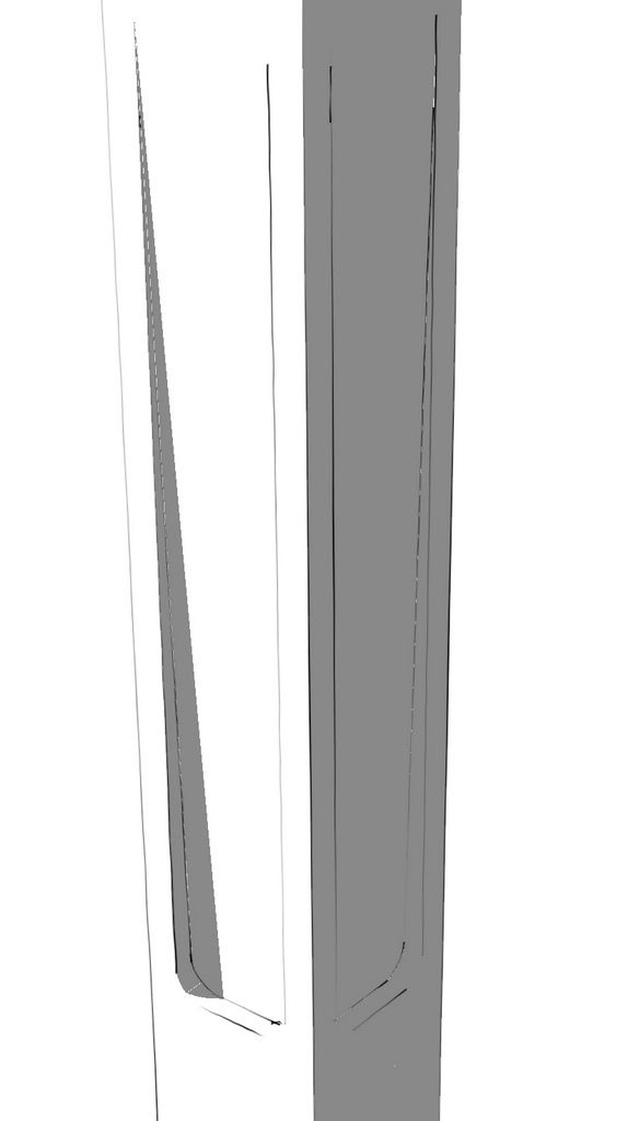
One of our readers asked about how to draw the indent detail from the Greene and Greene-designed Blacker House chair legs. As with most procedures, there are perhaps a number of ways to approach this one. This method is fairly straightforward and could be applied to other details as well. I’m basing my drawing of this indent detail on the book, Greene & Greene Design Elements for the Workshop by Darrell Peart. He cuts the indent with a router and a 1/2-in. diameter bit. I find it useful to think about the volume of space the cutter will pass through and then draw that.
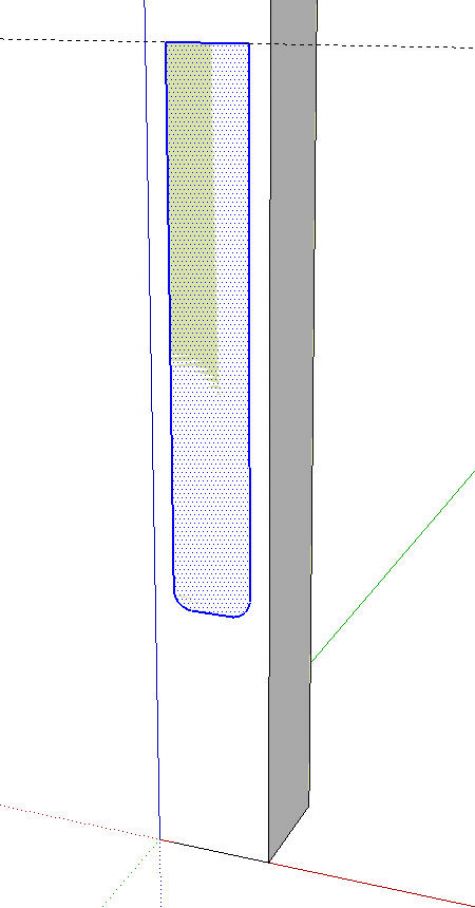
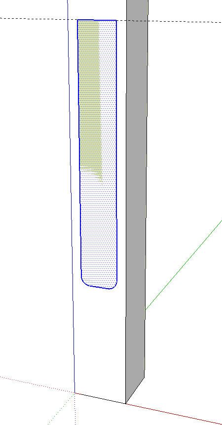
I drew a leg blank and made it a component. Then, on the front of it but outside the component I drew the shape of the indentation, shown in green. The length is based upon the jig shown in Mr. Peart’s book. I rounded the corners with 1/4 in. radius arcs since the cut would be made with a 1/2 in. bit. I drew this profile outside the component so I didn’t have to worry about modifying the leg until I was ready. This also prevents an intersection before I am ready for it.
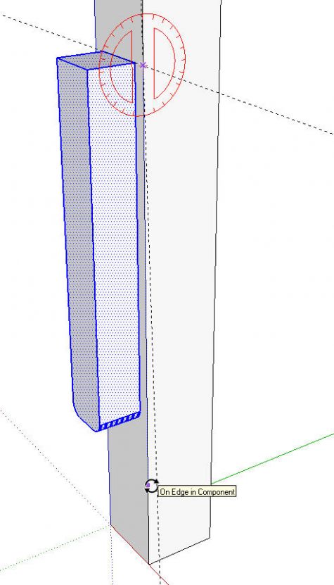
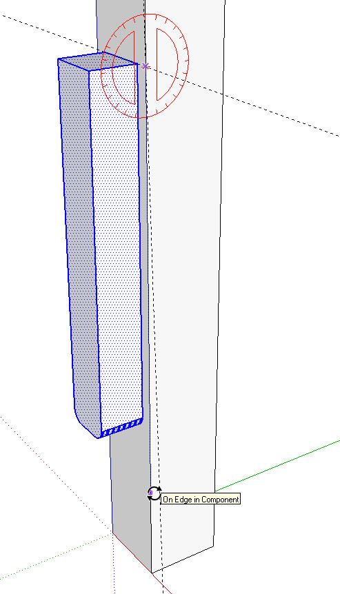
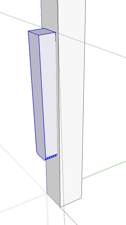
Next I used Push/Pull to extrude the profile. The exact distance isn’t important here. I also drew in an angled guideline along the side to give me a reference. In the case of Mr. Peart’s jig, the slope is 1/4 inch in 10 inches. I put in the guideline with the yellow Protractor tool. For the slope I entered .25:10 and hit Enter. Then I selected the extruded profile and Rotated it to that angle.
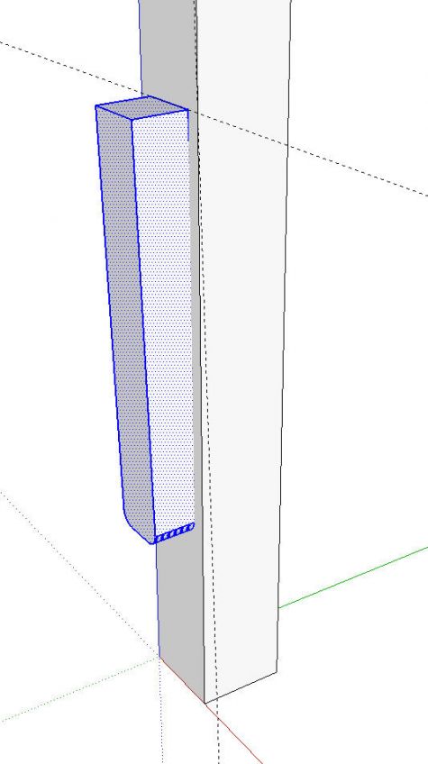
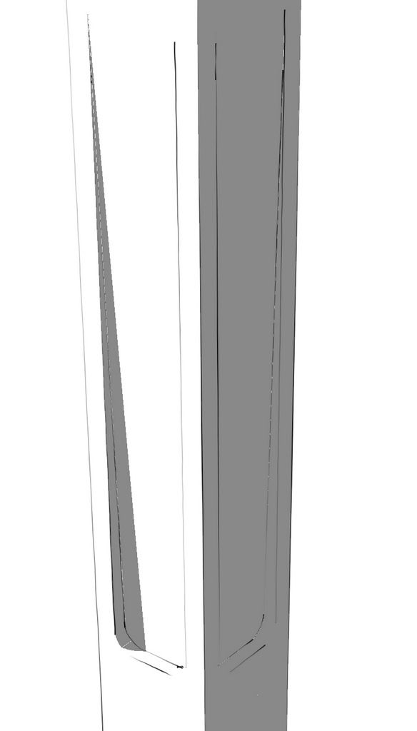
Next, I cut the extrusion. this is done with the Cut (scissor) tool on the toolbar or Cut in the Edit menu or Ctrl+X/Option+X on the keyboard. The extrusion disappears temporarily but not to worry. Open the leg component for editing and then, from the Edit menu, choose Paste in Place. The extrusion is pasted into the component in the same location. Right click on the extrusion and choose Intersect>With Model. Delete the waste, soften the edges between the curved surfaces and the flat ones then correct the face orientation.
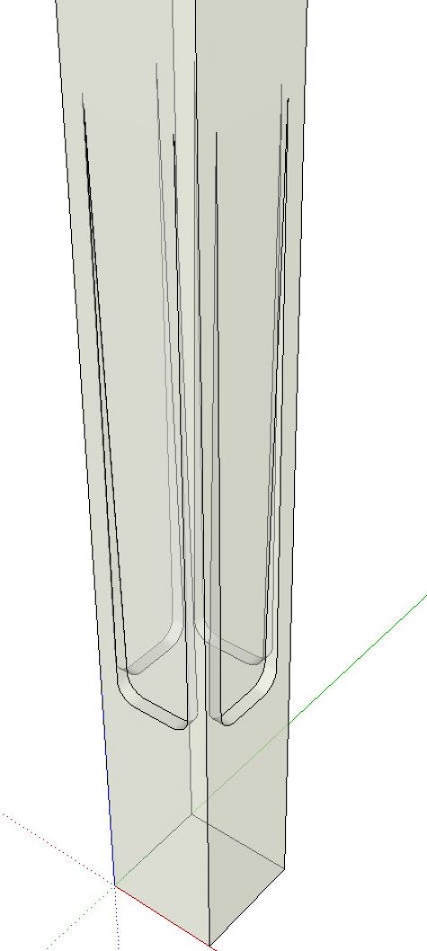
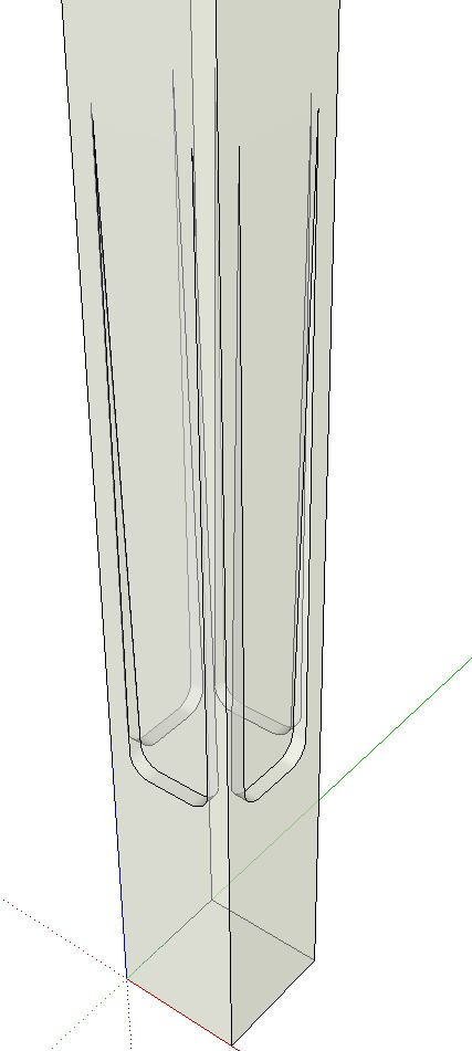
To place the indentation on all four sides of the leg, select all of the detail with a left to right selection box. Then use Rotate/Copy to copy the profile while rotating on the center of the leg. Rotate the first copy 90°, hit Enter and type *3 to make three copies of the original.
In this X-ray view you can see the indent on all four sides of the leg. In this instance the face skinning the indentation was removed automatically but that may not always happen. It depends upon the profile. If it doesn’t get removed automatically, you can select the face and hit Delete. You may find that you need to select all of the leg and the details and run Intersect>Intersect Selected prior to deleting the unwanted faces.
So, in a nut shell, draw the volume of space the cutter would occupy during the cut if you were using a router or other cutting tool. Then move the volume into the thing (board) that gets the cut. Intersect the volume with the ‘board’ and delete the waste. You could use this same idea for any sort of routed profile such as stopped flutes on a pilaster or the channel on a plate shelf for the lip of the plates.
Give it a try and, if there are any questions, feel free to ask.



Comments
so simple and very cool! I use a very similar technique when doing tapered curved legs on more than 1 side. pull out the shape, then move it inwards, intersect and cut the reminders.
I like the way accuracy is maintained by copying /rotating the indentation on the other 3 sides
Thanks for illustrating a technique which I know I will be able to use in other situations.
Jonas Mac
Thanks Dave for responding on my request. It would help to make my designs look more like the real thing.
Very cool - are you going to show us how to do the little knurled ends for the foot?
jcsssssssssssssss, just draw the curved profile on one face of the leg. Then use Follow Me to run it around all four sides of the leg.
Dave
Log in or create an account to post a comment.
Sign up Log in