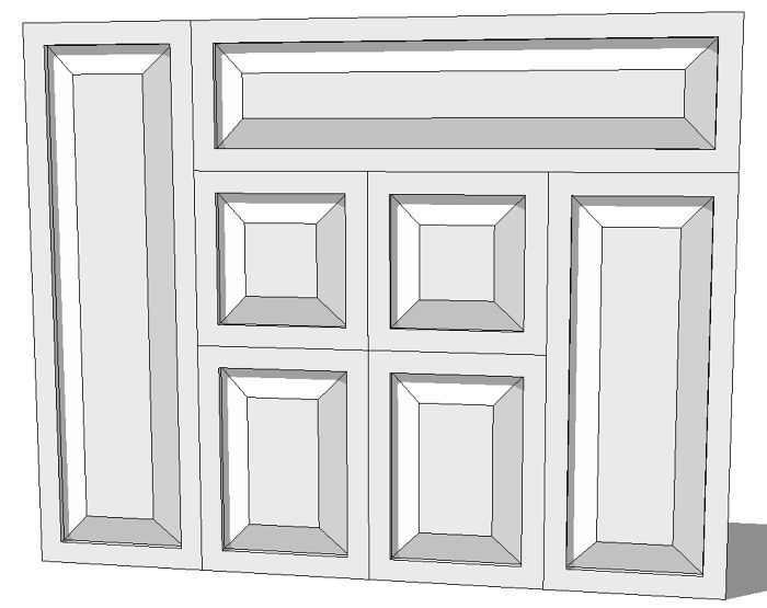
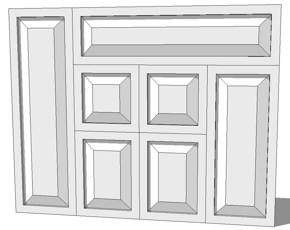
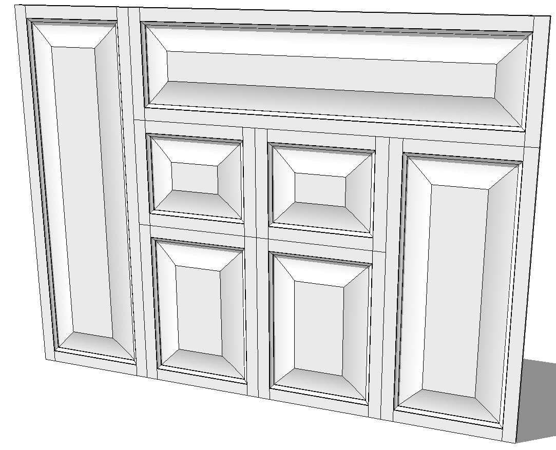
By request, here are a couple of easy ways to draw raised panel doors. The first way results in a single component that a client would recognize but which doesn’t take much time to draw. The second way, while still easy, is a little more involved. It results in five distinct components from which you could get cut list information and show exploded views if desired. The doors drawn by both methods are easily resized with the native tools so either way, you should be able to put doors on all of the cabinets in your kitchen using the first one you draw.
The Down and Dirty Way
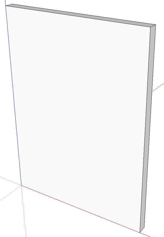
Start by drawing a rectangle on the ground plane to the width and thickness of the door.
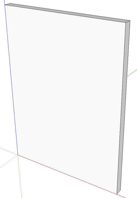
Use Push/Pull to pull the rectangle up to the height of the door. If you want slab doors, make this a component and you’re done. Otherwise on to the next step.
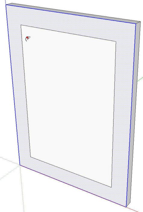
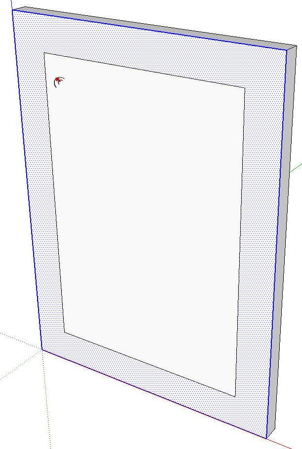
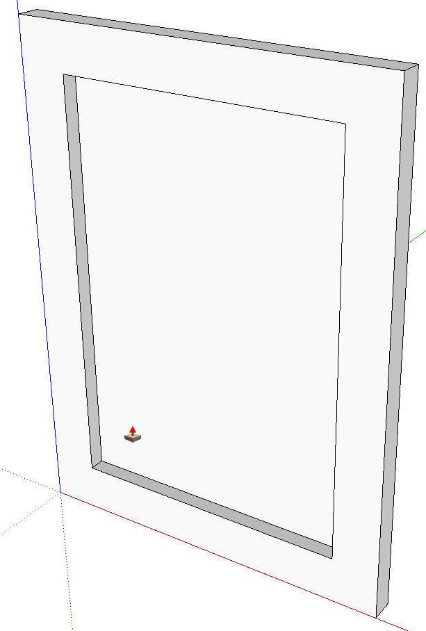
Select the front face of the door and get the Offset tool. Click on the outside edge and drag inward. Type the dimension for the width of the rails and stiles.
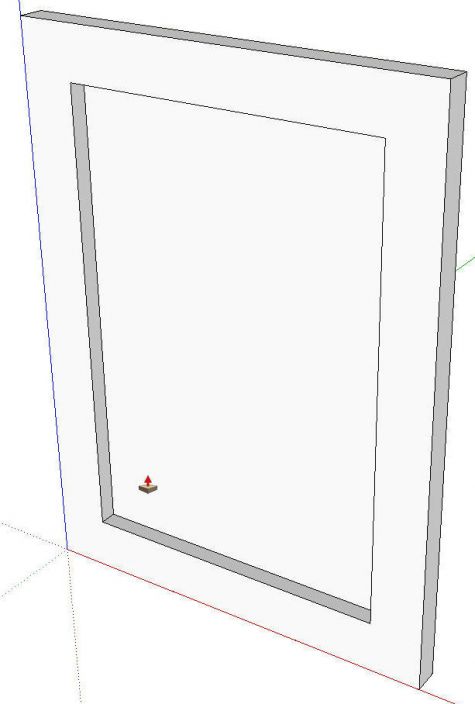
Get the Push/Pull tool and push in the panel. Need a Shaker-style door? Stop here and make it a component.
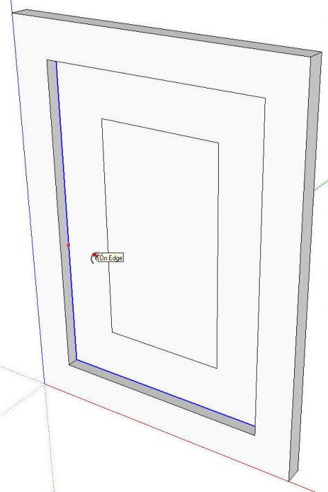
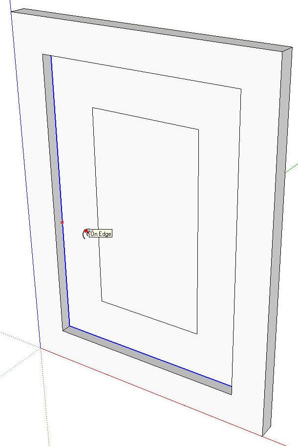
Select the inner face with a double click of the Select tool. Get Offset and drag in to the width of the raising. Type in the dimension and hit Enter.
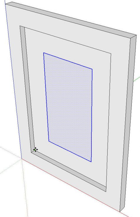
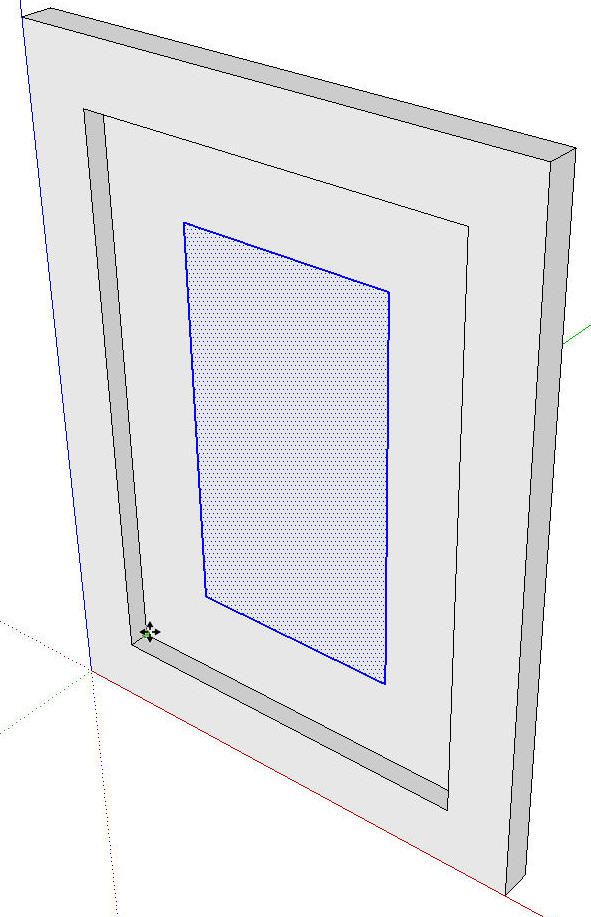
Get the Select tool again. The Space bar is the default keyboard shortcut for Select. Double click on the innermost face. this is the field of the panel. We want the face and its surrounding edges selected as shown.
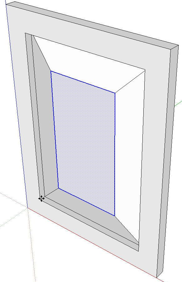
Get the Move tool and while holding the Alt (Command on Mac) to invoke Autofold, click and drag the selection forward. I followed the inside corner of the door frame because it was handy. Note: if you preselect what you want to move, you do not have to click on it with the Move tool to move it.
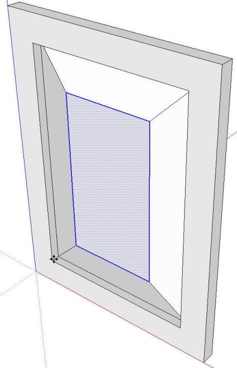
Now select all of the geometry and make a component of it.
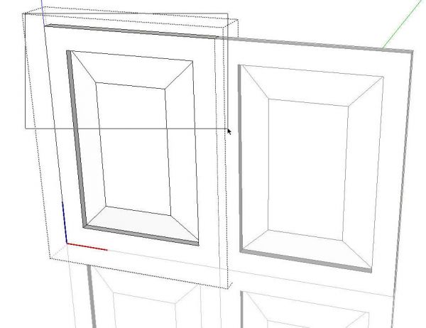
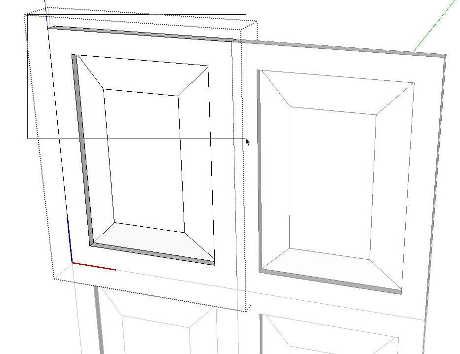
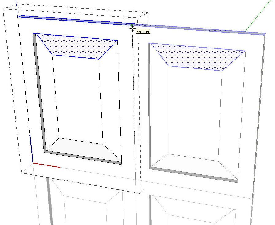
Now, if you need other door sizes, copy the component with Ctrl+Move (Option+Move on Mac) or bring a new copy in from the In Model Components Library. In the image, above, I made some additional copies. Before resizing the top pair, I selected both of them and right clicked to choose Make Unique from the Context Menu. Then I opened one of them for editing. Drag a left to right selection box around the top part of the door to select only those edges and faces at the top.
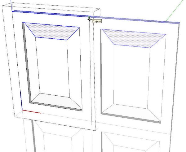
Then get the Move tool and move the selection the desired distance to make the new door height. Some folks might be inclined to use Scale instead of Move but that would also result in scaling the width of the rails as well as the top and bottom raisings on the panel. Move doesn’t cause that problem.
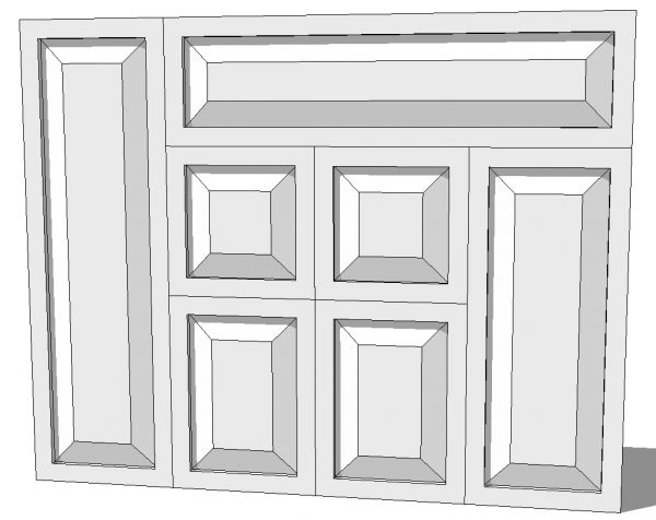
All of the door components, above, were made from a single door component.
A Slightly More Involved Way
Now here’s how we can make all five parts of the door as separate parts.
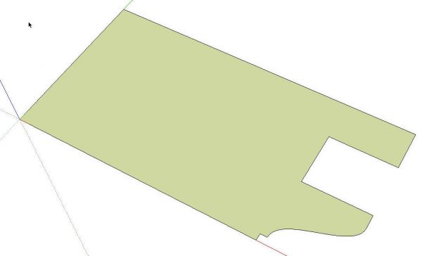
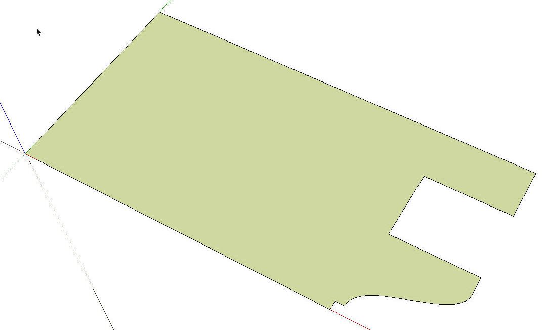
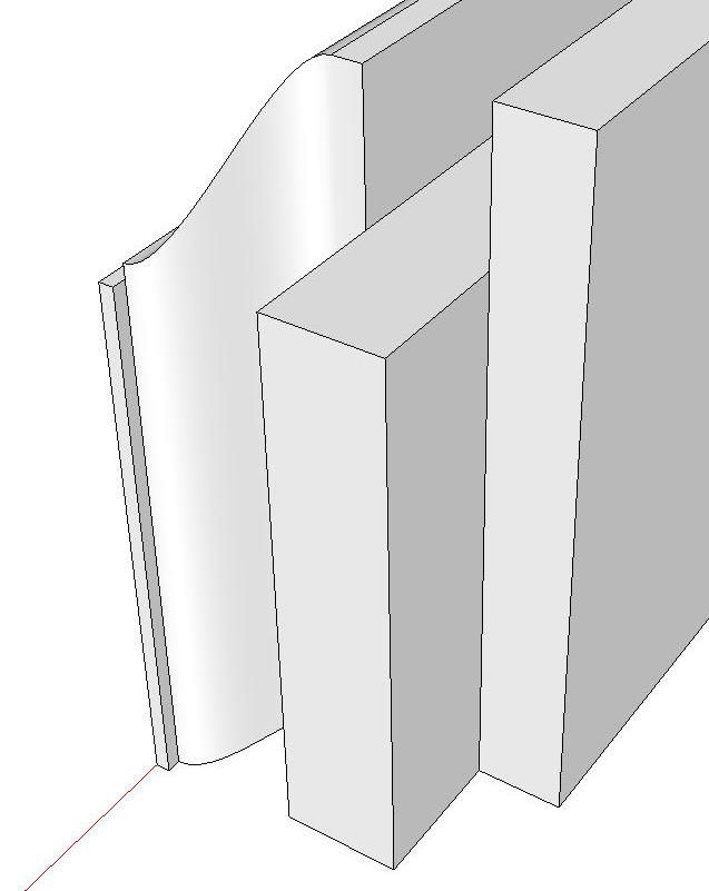
Draw the end of the stile. Unless you’re creating a template to have a cutter made, you don’t need very much detail nor does it have to be very accurate. Keep the segment count on the curves low to help control file size.
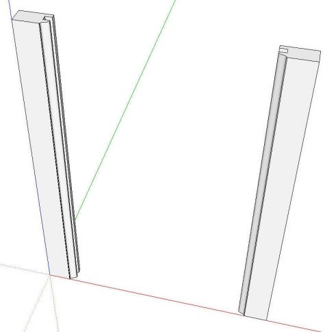
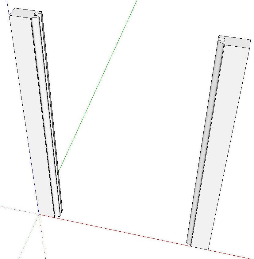
Pull the stile up to length with Push/Pull. Make it a component and copy it over to the opposite side with Ctrl+Move (Option+Move on Mac) and then right click on the copy and choose Flip Along>Component’s Red. We’re after a mirror image of the left stile. Rotating the stile end for end would seem to work but if you resize the components later, it’ll increase your work.
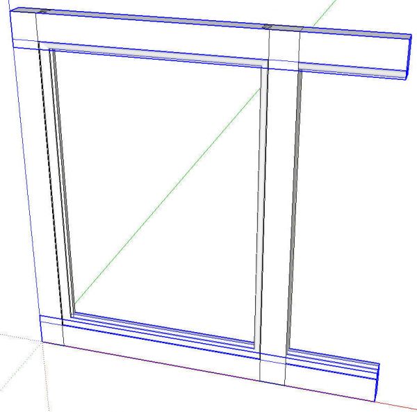
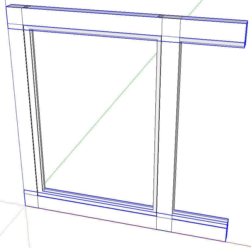
Instead of drawing the rails, I just rotate/copied the stiles and then moved them into place. They are longer than needed but that doesn’t matter. With both rails selected, right click and choose Make Unique to break their relationship with the stiles. Open the Entity Info dialog box and change the definition name to ‘Rail’.
Next select the two stile components. Hit Ctrl+C (Option+C on Mac) or Edit Copy or the Copy button on the toolbar. This puts copies of the stiles on the clipboard. Right click and choose Hide.
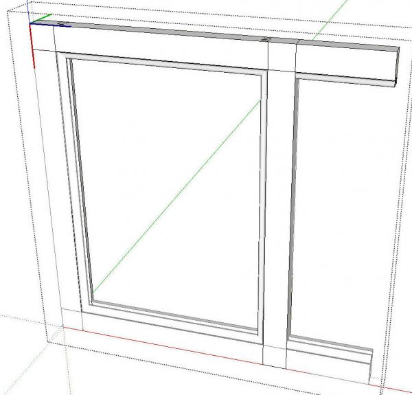
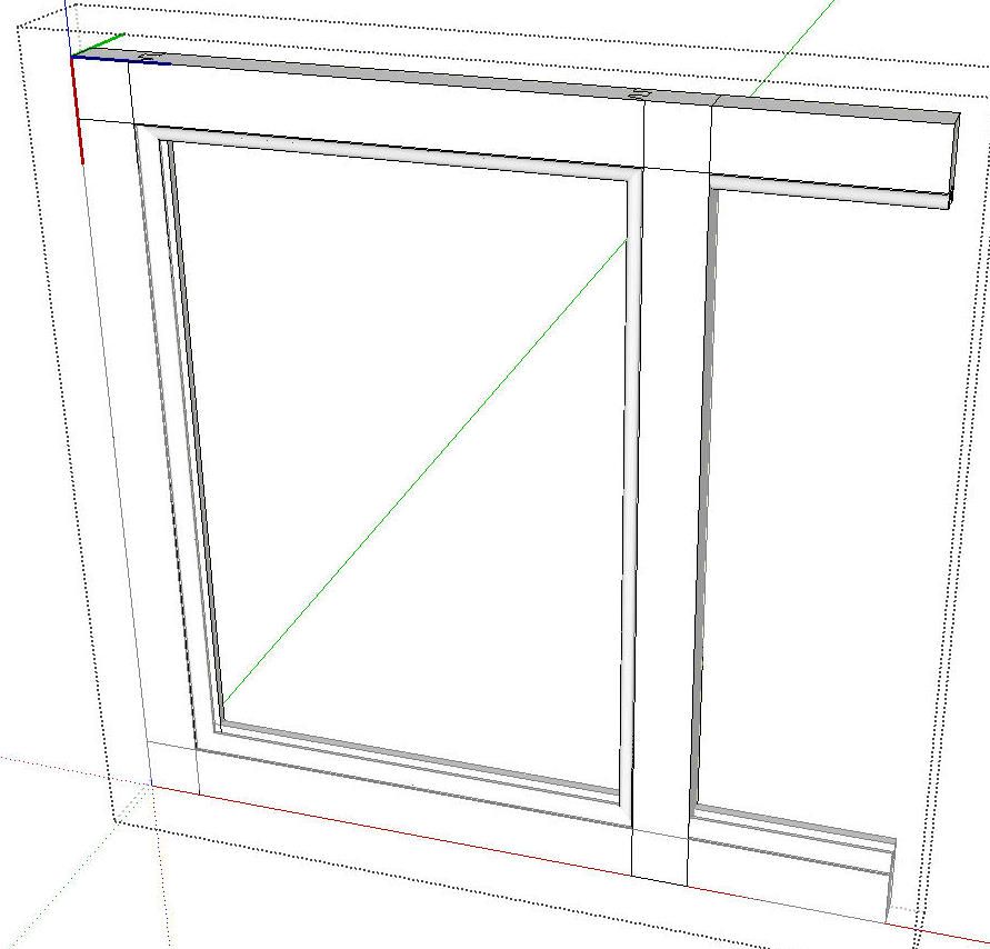
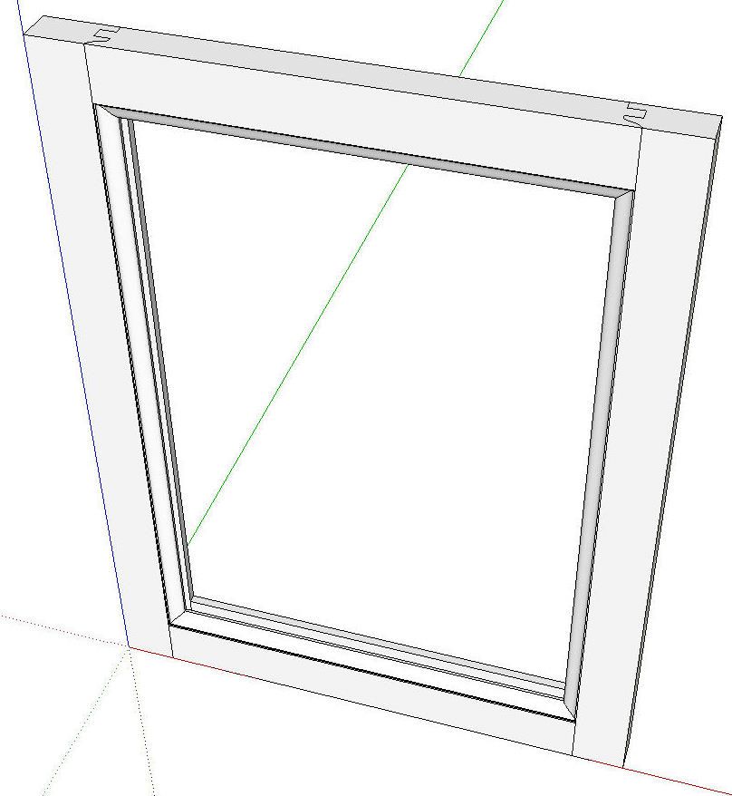
Next open one of the rail components for editing. I opened the top one. Go to the Edit menu and click on Paste in Place. The clipboard copies of the stiles will now be pasted inside the rail component. While the two stile copies are selected, right click and choose Explode. Select all of the geometry of the rail and the stiles, right click and choose Intersect>Intersect Selected.
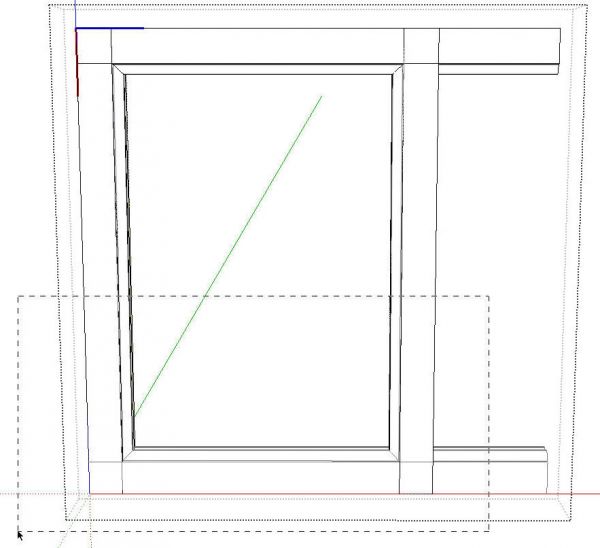
Now it’s time to get rid of the unneeded stuff. A right to left selection box around the bottom end of the stiles followed by a tap on the Delete key will get rid of them.

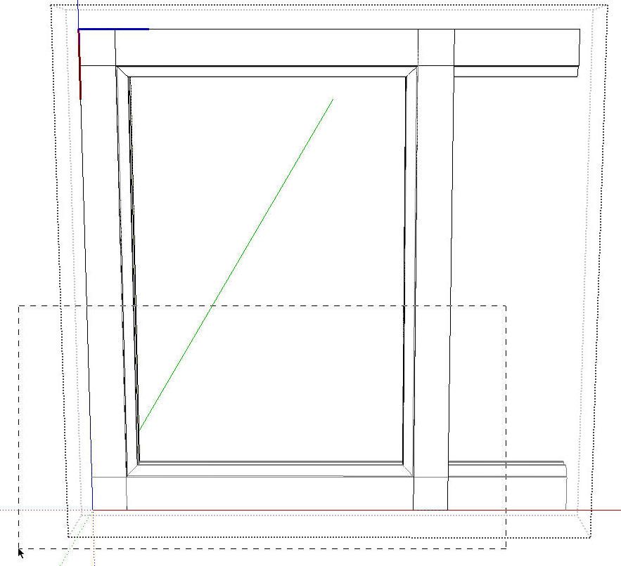
A right to left selection box around the stuff to the right of cope and another tap on the Delete key will take care of that end. Do the same at the other end. Make sure you don’t delete anything you need.
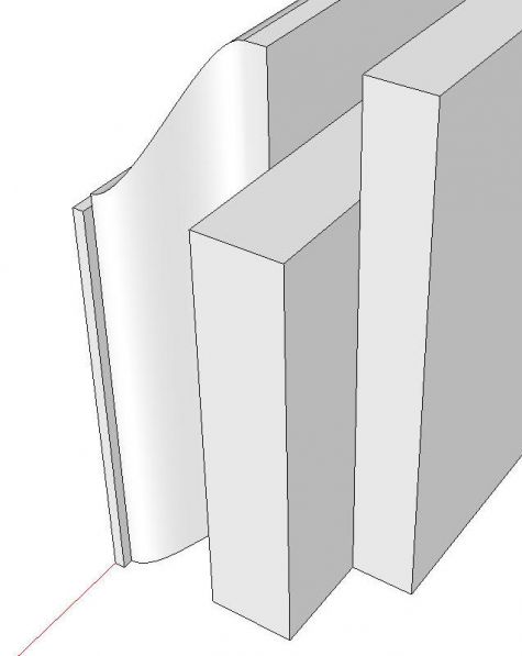
Look closely to see if there’s more geometry to delete. Also check for missing faces due to the intersect operation creating small faces. If you have small holes, undo back to before the Intersect operation. Then Scale the entire component up and redo the intersect and delete operations. Then scale back down. Do you good housekeeping and make sure you correct the face orientation so the back face colors are on the inside. Go to the Edit menu and click on Unhide>All.
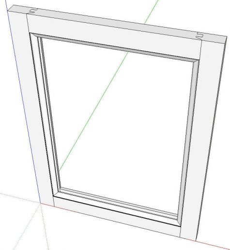
That’s takes care of the frame now on to the panel.
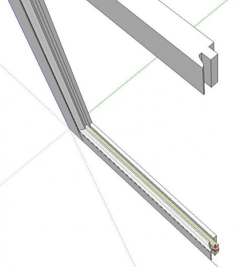
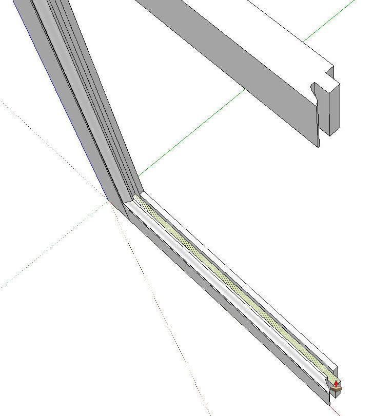
I hid the right stile and zoomed in to the slot on the lower rail. There I drew a rectangle on the bottom of the groove. Push/Pull brings the panel up to the bottom of the groove in the top rail.
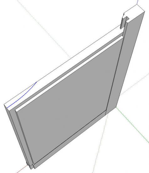
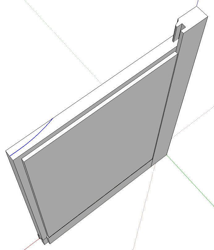
I used Offset and Push/Pull on the back of the panel to create the rabbet. I pulled the front of the panel out to the front of the rails and stiles. Then I drew the raising profile on the edge of the panel. Then I used Follow Me to extrude the profile around the edges of the panel. Finally, I made the panel a component.
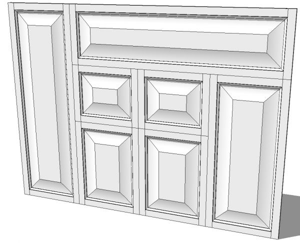
As before all of these doors were made from a single set of components. Push/Pull works on the ends of the stiles and a selection box around the end of a rail or panel followed by Move will take care of those parts. Just remember to use Make Unique on components whose dimensions will be changed Only use Make Unique on those components that will be resized, though. Keep all the like components that are the same size related. This will make your cut list more efficient.
To make the doors easier to handle you might select all five components and make a nested component of them. That will make them easier to move around the model. You can also save those components in a local collection for later use in other models if you wish.
One last thing I would like to point out about the way I drew the five-piece door. Everything was drawn in place. Once I had the stiles in place, all of the other dimensions of the door parts are based on them. I didn’t draw any components somewhere else and move them into place.




Comments
Great article - thanks! I'm new to SkethUp and tips/techniques are a real help. Question: At the start of "A Slightly More Involved Way" the stile profile is drawn in green. How did you draw the curved part of that profile in SketchUp? It's not made with basic arcs...
This might sound odd but is a "right to left" selection box different from other types (top to bottom, etc.)?
Thanks!
Hi Oaktonwoodworking.
I'm glad you liked this.
Good catch on the curve. The ogee curve on the stile profile was drawn with a plugin called Bezier.rb which is available here: http://sketchup.google.com/intl/en/download/rubyscripts/bezier.zip I've covered using it in several other blog posts here so take a look at them.
As to your question about the selection box, selection boxes are always dragged out diagonally. It doesn't matter if you drag top to bottom or bottom to top but it does matter if you drag left to right or right to left. A left to right selection box selects only entities which fall entirely within the box. A right to left selection box, on the other hand, selects entities that fall even partially within the box. Entities include edges, faces, components, groups, dimensions and other text.
FWIW, the green is the color I have set for back faces in my default style.
Dave
Log in or create an account to post a comment.
Sign up Log in