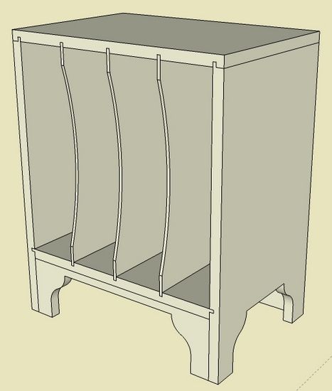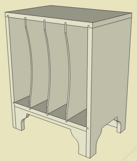
Following last week’s publication of “SketchUp Guide for Woodworkers”, I’ve received several questions on the making of the tongue & groove joints on the Magazine Rack. The specific reference in the book is Chapter 7, Page 31, and Step 4.
Here is a picture of the assembled Magazine Rack model.

Below is a video of my procedure for creating those joints in the top, side, and bottom shelf components. This may help clarify the written procedures in the book.


Comments
Thanks - I needed that
Great video Tim! That certainly eliminates any confusion regarding that section.
Tim:
I bought your book and am following the exercise. I am farther along, working on the 18th-century chamfered-post table. I am at the point where I need to make the mortise in the lower stretchers. In the book you indicate the tenons are to be 1 1/16 long in the stretchers. I did as instructed but now am having a hard time with the mortises. First I think the tenons are to long as they look as if they overlap in the legs. Second I cannot see the lines for the mortise in x-ray view. Is there any way to make the dotted lines show up better or another method of finding the right lines to follow?
In x-ray view the component lines a so light they are extremely hard to follow?
Thanks Bud
To Budlyte3: Thanks for the comments and congratulations on getting this far in the construction of the table. You are correct that the tenons are too long. They should be 11/16" not 1 1/16. Figure 16 on page 49 should say 11/16" on the tenon length.
For mortises in the Legs, I am assuming you are doing Step 19 as shown on page 50. There I am recommending to use the tenon on the stretcher as a guide to draw the mortise on the leg component. On some screens, it may be difficult in X-ray to see the outline of the tenon as it enters the face of the leg.
As an option, don't use X-ray and move the stretcher away from the leg slightly, say 5/8" on the red axis. Zoom in, and draw lines on the leg component where the tenon protrudes the face of the leg. Another alternative is to not use the stretcher at all, but on a copy of the leg, draw guidelines to create the border of the mortise location in the leg. Then use the Line Tool and Push/Pull tools to complete the mortise.
Tim
Video helps but in the book you tell us first to make the top and bottom into components by selecting the parts with the box method .I cannot seem to select just the top parts or just the bottom parts to make them components because they overlap the sides.
I ended up moving the sides away from the top and bottom so i could select them to make components. What did i do wrong?
Thanks for any help.
Tim:
Thanks for the response. After reading last comments and watching the video I tried the same technique and it worked a lot better. I think I have all the mortises in the correct positions. Now I need to go back and shrink the tenons. Will keep at it and again thanks.
Bud
To Larrythewoodguy, if I may offer this: It sounds as if you are drawing all of the parts for the cabinet and ending up with them all stuck together. Draw one part and then make it a component before you move on to the next part. Making the component prevents other geometry from sticking to it.
To Larrythewoodguy: As long as the sides are components, you can draw a select box over the graphics representing the Top, and make the Top a component. There would be no interference with the Sides even with the overlap. Same with the bottom shelf.
One thing that possibly could have happened is that you went right-to-left with your selection box. That would cause the sides to also be selected. The selection box must be from left-to-right so that only the parts that are fully enclosed in the box are selected.
Tim
Thanks, very helpful as I don't cope well with the spatial/3D/visual stuff. I am having similar problems with the rabbet on the back of the case. If I draw a horizontal guide line 1/4 inch up from from the back bottom lip of the top piece, open the top piece component for editing, and then draw in the lines on the back face of the top to create the horizontal rabbet, I end up with several individual planes (including the partitions), not one long horizontal plane. So to create the rabbet I have to push all the separate surfaces back one inch. Any ideas what I am doing wrong?
Regards,
Steve
Steve, sounds like your opening procedure is correct. But perhaps the Partitions have been mixed up with the component defining the Top. When you push back that rabbet, there should be no effect on the Partitions. And doing anything to the Partitions should not have any impact on the Top component.
You can send me your file on email ([email protected]). But first check that your Partition component is only the partition. And check that your Top component is only the Top. You can easily check this, by making a copy of either component, and moving it to the side.
Tim
Thanks, Tim. I can see several "strangers" in the top component when I make a copy off to the side as you suggested. Examination of the other components also reveals extras. I think I need to be more careful when push/pulling - I might not be actually eliminating waste, just pushing to the end of the component. Will press on and be more careful.
Regards,
Steve
I had pretty much given up on SketchUp. The on-line tutorials were a mess of information, so Sketch-Up basically just took up disk space on my computer. Your book got me started again this time in the right direction. While I haven't read it all and done all the exercises I have done enough to be able to design a book case complete with dovetail joinery, sliding bevelled dovetails for the shelves and a groove for the raised panel back.
Ahhh - now I just have to build it! ;-)
Log in or create an account to post a comment.
Sign up Log in