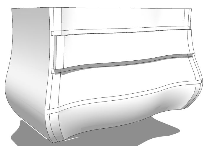
In part 1 of this series, I showed a way to create the complex surface on the front of a Boston Bombé chest. In this installment I’ll go through creating the case side, drawer fronts and the rails between the drawers which are dovetailed into the sides. Let’s dig in.
Later in the demo I used the components with the Solid Tools because they make much quicker work of the process but this piece can certainly be drawn without them. I’ll describe how when I get there.
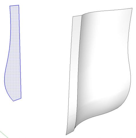
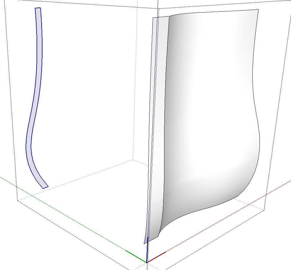
The surface on the right is what we ended up with in the previous part. Actually it was divided into four groups because of the way I used the Extrude Tools. I exploded these groups and softened the edges between them resulting in a single large surface which I made into a component
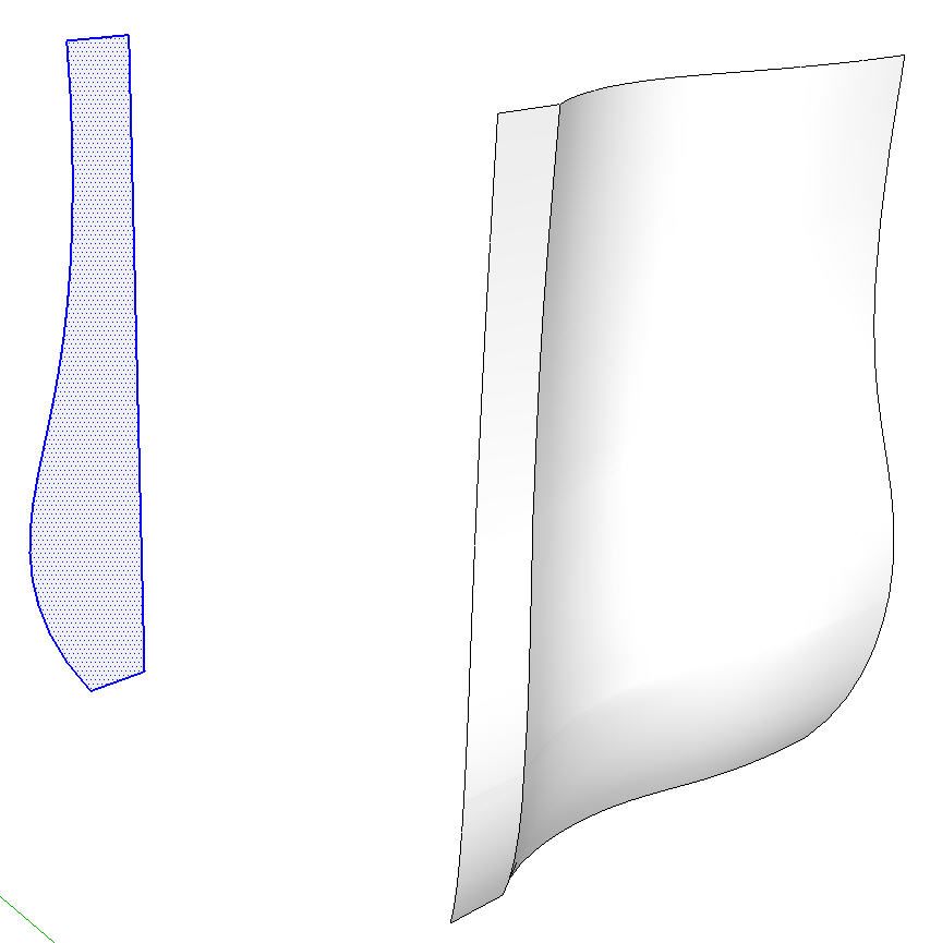
The selected surface on the left is from the curve component I made for the side of the case. Since it was a component, I imported a new instance from the In Model library and located it at the back of the case. Then I exploded it.

Here’s a close up of that face on the left in the previous image. I selected the curve and then the Offset tool. I offset the curve inward to the thickness of the case side. Notice there’s a gap at the bottom. This is common but easily fixed. I just got the Line tool and extended the last segment in the curve to the bottom edge. To extend the line in the right direction I clicked on the end and then dragged the cursor back up last line segment. I held Shift to lock the direction and then moved the tool toward the bottom edge where I clicked to create the intersection.
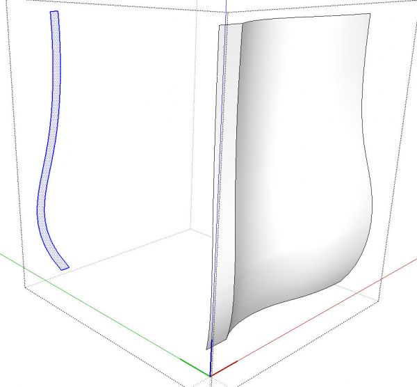
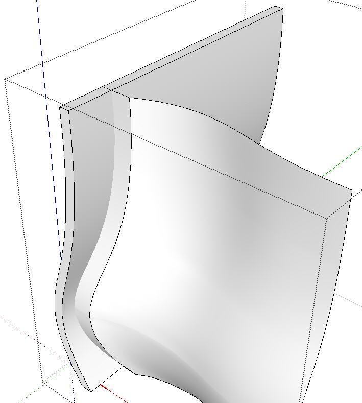
With the inner curve completed, I delete the unwanted part leaving what amounts to a cross section of the side. I then selected that section and used Cut (Edit>Cut, Ctrl+X, Command-C or the Scissor tool) on it. I opened the front component for editing and used Edit>Paste in place to put the profile inside the front component. You can see the large box of black, dotted lines surrounding the open component.
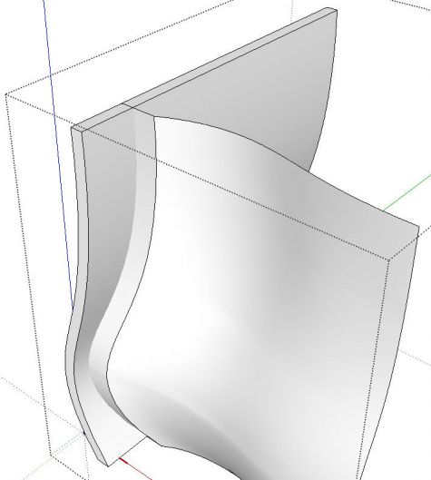
I used Push/Pull to pull the profile out past the front. Then I selected all of the involved geometry, right clicked and chose Intersect Faces>With Selected. If you are still using SketchUp V7.1 or earlier it would be Intersect>Intersect Selected. Same results. I deleted the faces and edges in front of the front surface to clean up the intersection.
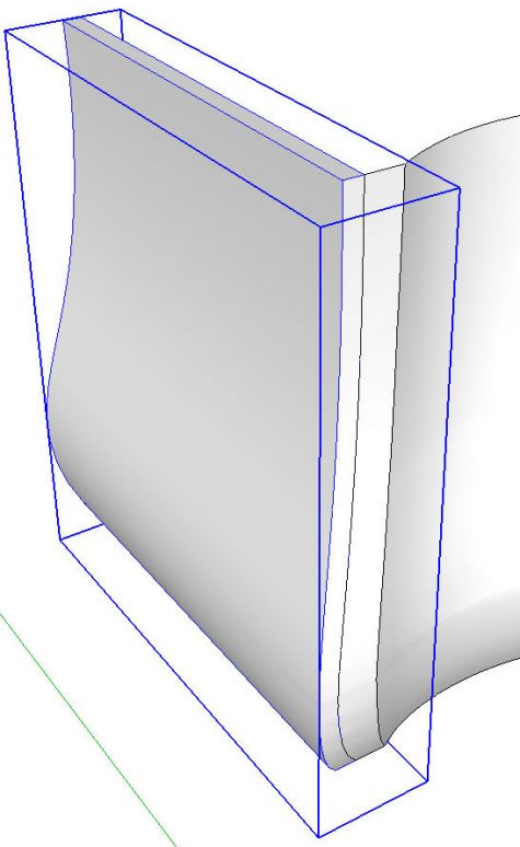
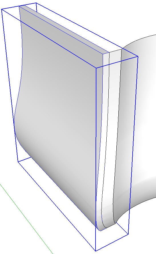
Next, I selected the faces that make up the case side and hit Ctrl+C (Edit>Copy, Command-C or the Copy tool on the toolbar) to put a copy on the clipboard. Then I deleted the visible side geometry. I closed the front for editing by clicking in space with the Select tool. Then I used Edit>Paste in place to put the copy of the side geometry in place. This was then made into a component as shown by the blue bounding box, above. We can’t use Cut in this case because we would end up taking the curve between the side and the front which we still need to have in place on the front.
At this stage I created a layer for the case side and then associated that layer with the side component. Of course the geometry in the component remains on the default Layer 0. To get the side out of the way for the time being, I turned off the visibility for that layer.
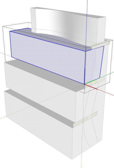
Now it is time to move on to the drawer fronts. I opened the front surface for editing and made a ‘solid’ by drawing in some lines from the corners back parallel to the green axis and joined them with a rectangular face behind. I did this so I could use the Solid Tools to create the drawer fronts and rails. Then I drew cross sections for the drawer fronts and rails making each a component as I went. The back edges of the sections are drawn for where they’ll be in the final parts. the front edges were drawn just so they extend fully beyond the curved front surface.
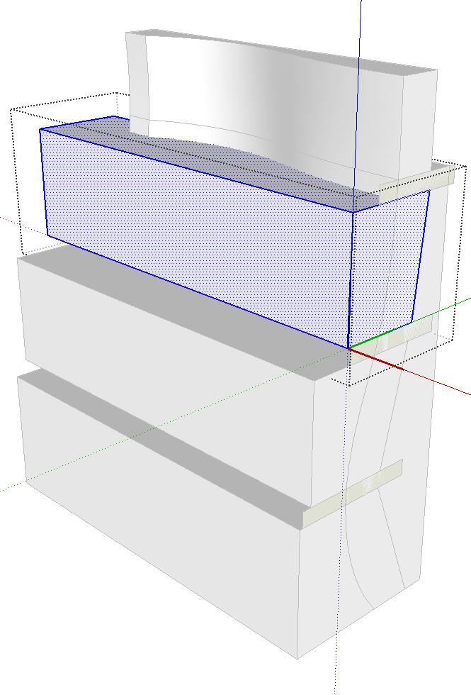
In the image above, I’ve extruded the drawer front blanks beyond the left edge of the curved front. The sections for the rails are left for the time being.
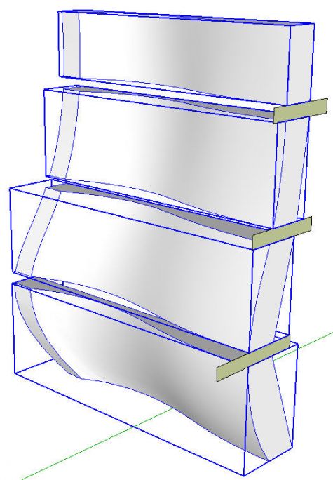
Next I used the Split tool to create the drawer fronts. This is extremely fast because you just click on a drawer front blank and then the solid with the curved front surface. I deleted the waste from the drawer fronts and, for the image above, I hid the remains of the curved front surface. With the drawer fronts made, I created a layer for them and made the layer associations for the components.
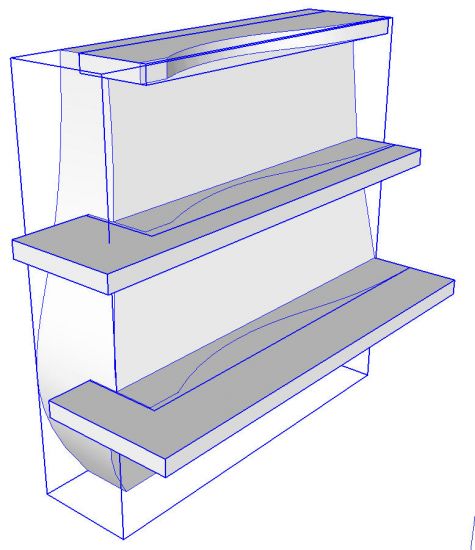
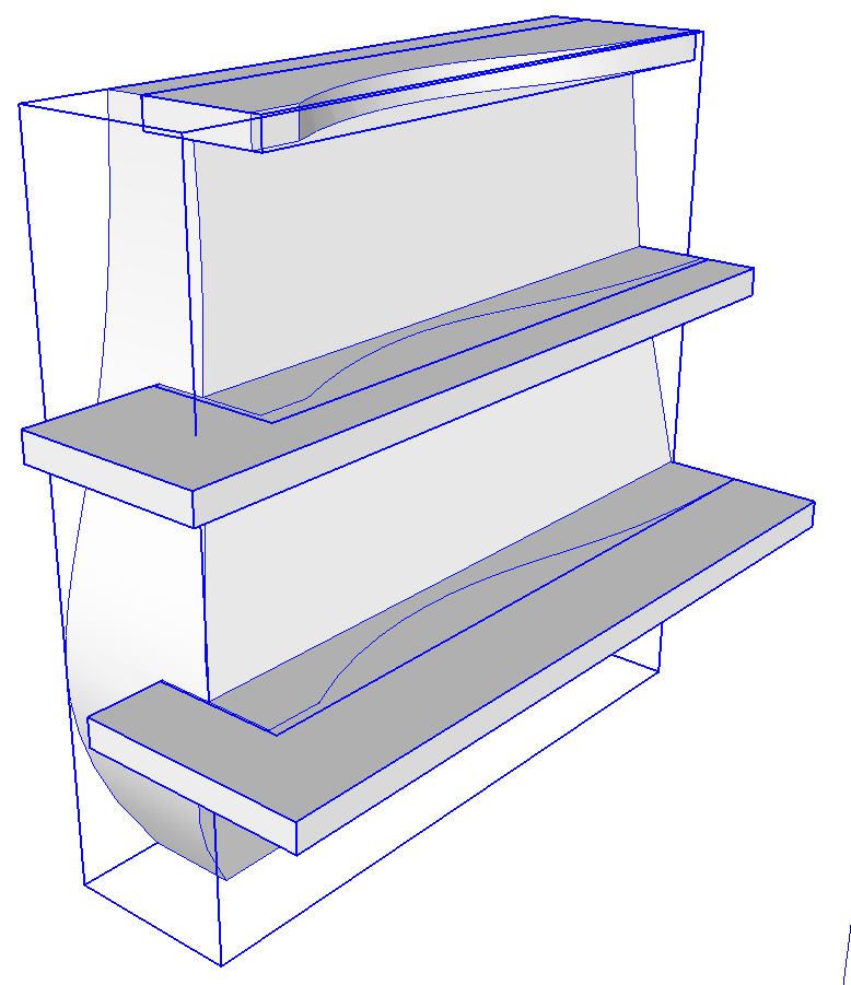
In this image I’ve turned off the drawer layer, unhidden the remainder of the front surface component, extruded the rails and then used Split. The waste on the top rail component has been deleted.
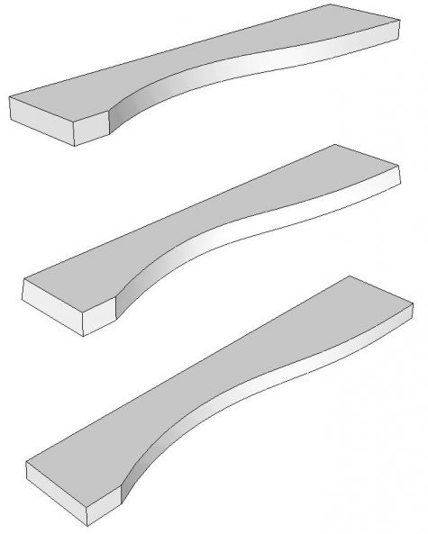
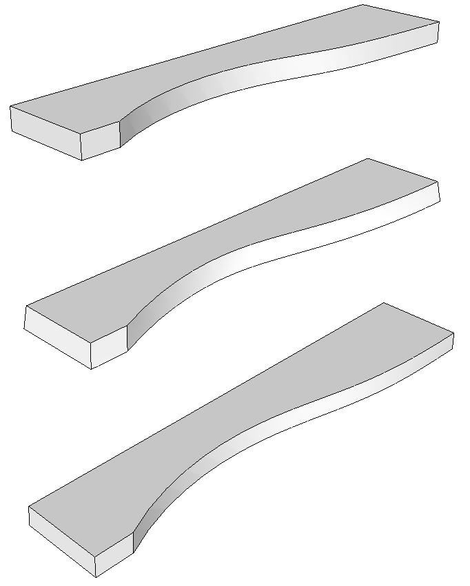
After deleting all of the unneeded bits, we are left with the rails. After all of that Trim work we are left with ‘Solid Groups’ instead of components. I prefer only components in my models so I convert them back to components and give them proper names so I can identify them later.
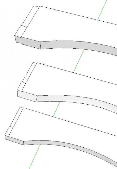
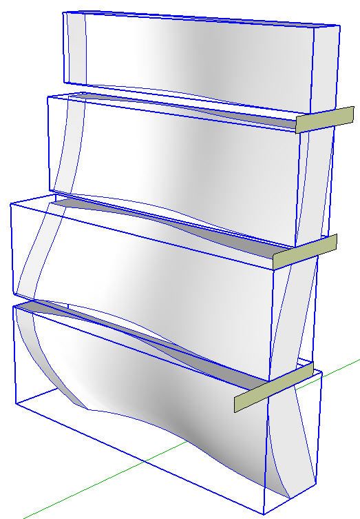
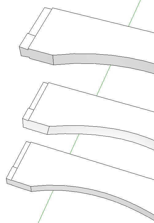
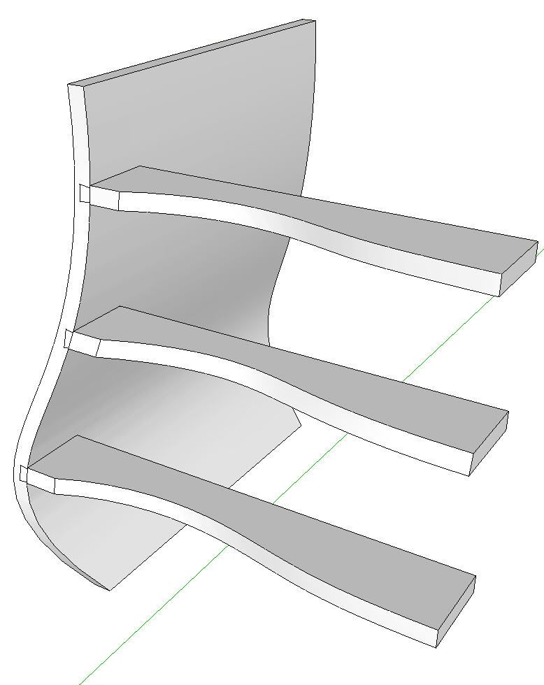
Here I’ve added the dovetail/tenon to the ends of the rails. This is done by editing each component and adding the required geometry. The front edges of the rails are not flat so you’ll have to create the faces with some triangulation. I thought about adding the dovetails before doing the Trim operations but this would result in cutting the dovetails off. If I had kept the original front surface I could have probably gotten away with drawing the dovetails first.
To create the rail and drawer components without Trim, you would forgo making the solid of the front surface. You would then copy the front surface into each drawer front and rail component, run intersect and delete the waste. To get the proper curve on the ends of the drawer fronts and rails, you’ll need to include the side profile as well. The end result will be the same as what I show above but it will take a bit more time. Remember to correct face orientation as needed.
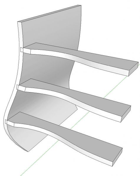
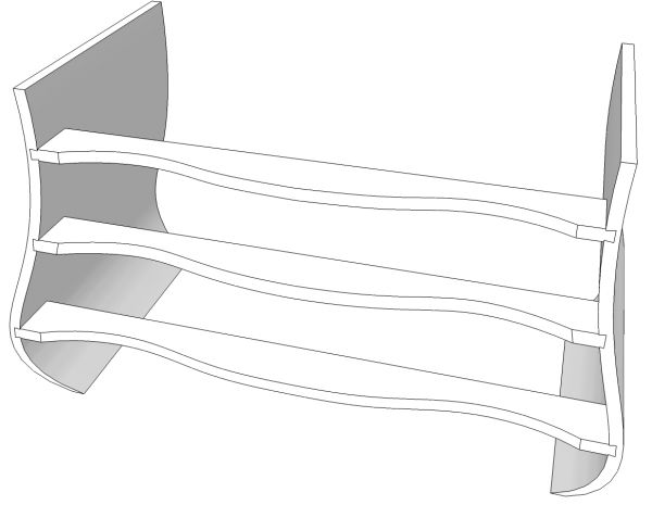
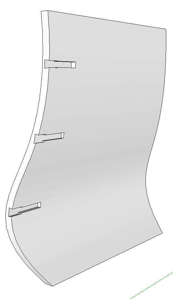
To create the sockets for the dovetails I used the Trim tool to trim the rails from the side.
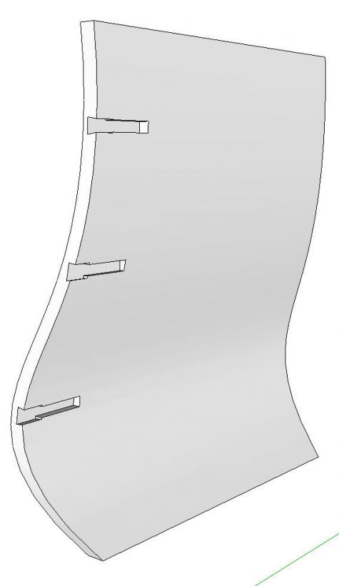
With the Rail layer turned off, you can see the sockets left in the case side.
To create these sockets without the Solid tools, open each of the rail components for editing, select the geometry and copy it. (Ctrl+C, etc.) Then open the side component for editing and use Edit>Paste in place. Turn off the Rail layer and run Intersect on the geometry in the side component. Delete the waste and correct the face orientation. Note that Intersect with model won’t work because it won’t generate the internal faces and edges. You’ll be able to get part of the joint drawn but not all of it if you try to just intersect the components with each other.
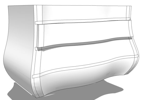
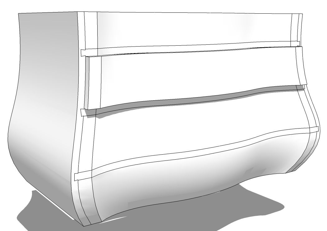
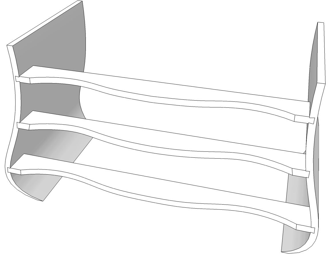
For this image I’ve copied the rail and side components and then flipped the copies. They were moved into place to create the right half of the cabinet. I opened an instance of each of the rail components in turn, deleted the face at the end and hid the edges to hide the seam line. I did the same for the drawer fronts as well. If the face in the seam is not deleted it will show through even with the edges hidden.
The rest of the chest is rather straightforward stuff. The internal structure is typical dust frames which are joined with mortises and tenons. To create the top, I would open the top drawer front and the side in turn and copy the top exterior edges which I would then paste in place outside the components to use as a path for a Follow Me operation on a profile of the top edge. The bottom of the case could be done the same way. Tim has shown a simple method for doing the legs by intersecting two shapes and deleting the waste.
The inspiration for this piece has cock beading around the drawers. As for the top, I would copy out the edges to create paths and draw a profile of the cock bead for Follow Me.
While you may not be interested in this style of furniture, I hope you’ve been able to glean a little tidbit or two that you’ll be able to apply in your drawing projects.




Comments
That is really COOL... Super procedure!
Thank you!
David,
Your presentation if very interesting and informative. Thank you for posting it. As for what the final project might look like, one can look at Tommy MacDonald's gallery of photos of his "Boston Bombe" secretary. For those who are interested, here is a link to his creation.
http://www.thomasjmacdonald.com/content/galleries/t-mac-furniture/bombe-secretary/
Bruce
Log in or create an account to post a comment.
Sign up Log in