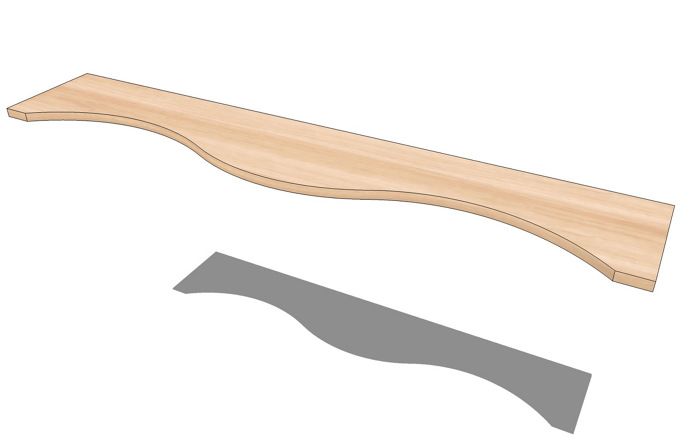
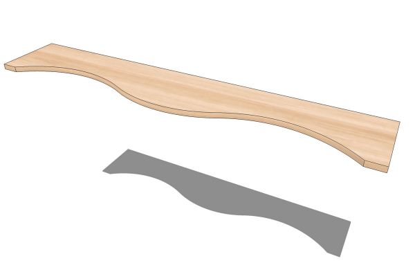
The other day a Knots member asked a question about laying out the arcs for the front edges of the shelves and top on C. Michael Vogt’s bookcase featured in Fine Woodworking from Jan/Feb 1995. It’s also shown in the book, “In the Craftsman Style.” He wanted to know how far from the ends the narrowest part of the shelf falls. There are several ways to do this in the shop. Perhaps the easiest way to layout the curve would be to use a thin batten flexed with a piece of string to the desired radius. Of course you could also work this out in SketchUp quite easily and perhaps use the result to print a full size pattern.
Here’s a way to take the minimal information about the wave and draw it in SketchUp. We’re going to use a script called Point at Center. It’s a native plugin but if it is new to you, you may not have made it available. To enable it, open SketchUp Preferences. On the PC go to Window>Preferences, on Mac click on SketchUp>Preferences to the left of the File menu. Choose Extensions from the list on the left of the Preferences window. Check the box for Ruby Script Examples. If you haven’t been here before, check all the other boxes while you’re at it. Click OK to close the box.
And now on with the show. I drew the board to the overall dimensions and made it a component. I’ll draw the curve outside the component and when I am satisfied with it, I’ll add it to the component. By working this way I can avoid modifying the component until I’m ready to do so.
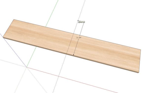
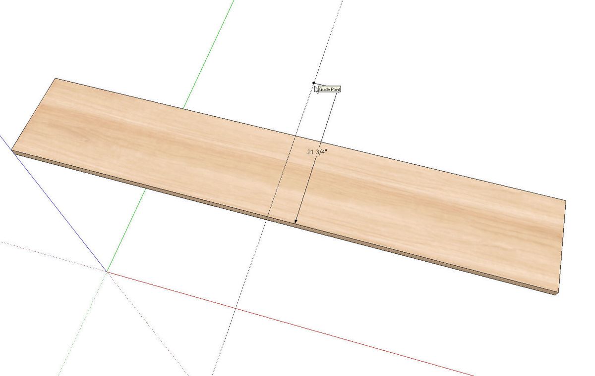
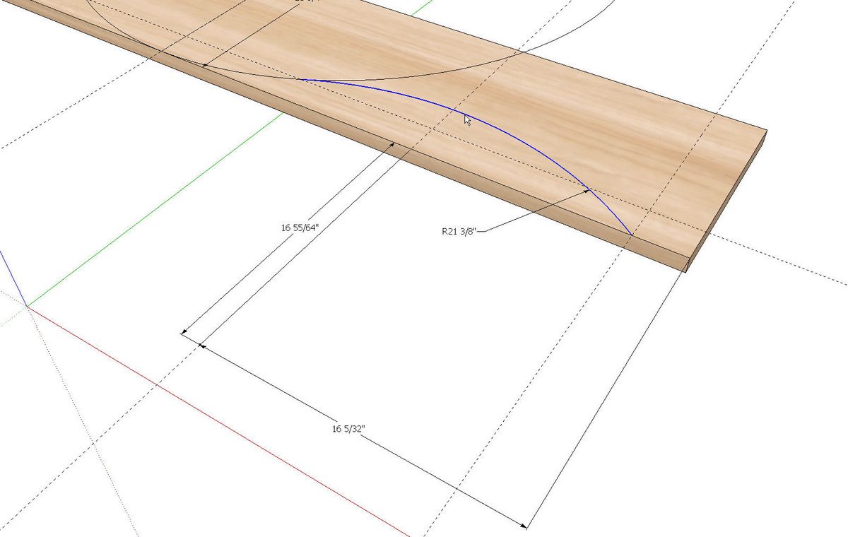
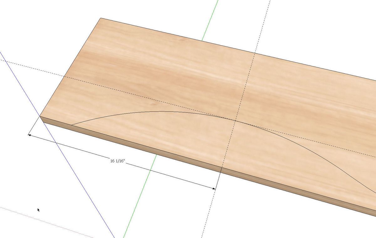
I’m starting with the central arc. I put a guideline at the mid point of the board using the Tape Measure tool. A guideline is created when you click on an edge, axis or another guideline. Then I measured from the front edge of the board back along the guideline to place a guide point at the center of the arc (21-3/8 in.). By starting the Tape Measure tool at an intersection or end point, we get a guide point instead of line.
I added a dimension for illustration but wouldn’t normally use dimensions at this stage.
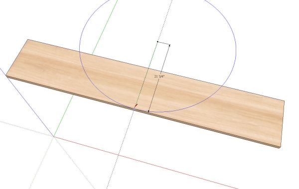
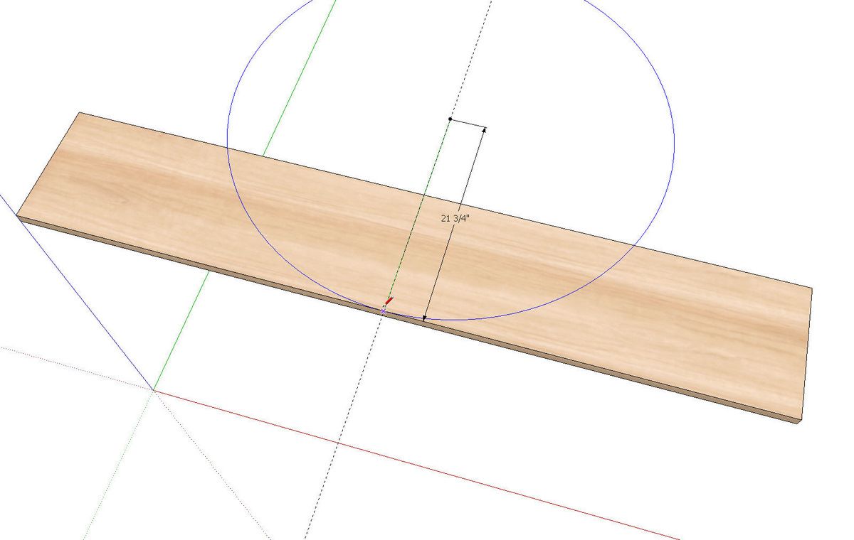
Next I drew a circle with a radius of 21-3/8. To make this curve smooth, I increased the number of sides on the circle to 96. Before starting to draw the circle I typed 96S and hit enter. I’m using a circle instead of an arc here because at this stage I don’t know where the arc would end but I do know where the arc’s center is.
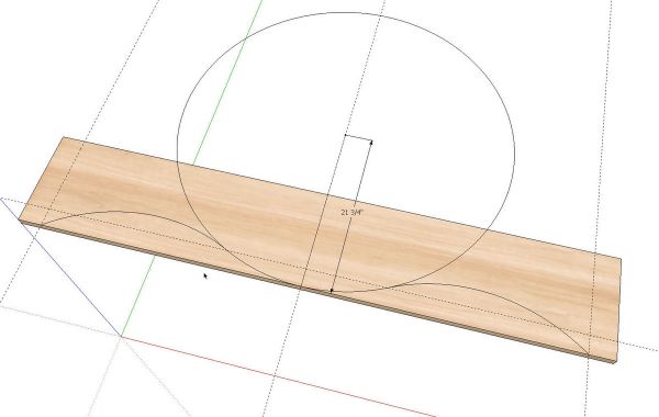
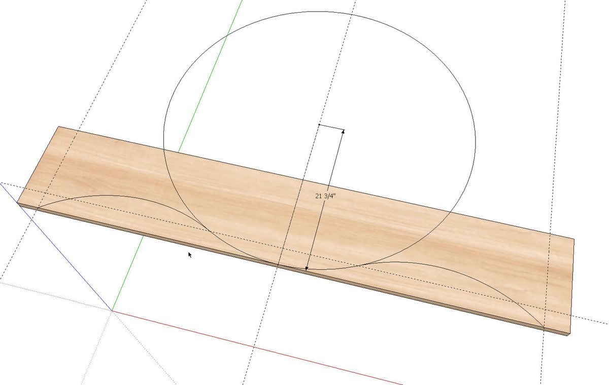
For the concave arcs, I placed guidelines for the ends and drew the arcs from those points to the circle. I used 48 segments for these arcs to smooth them out. I did one of them and then zoomed in and set the camera so I was sighting down the curve to make sure it looks alright. Then I placed a guideline parallel to the front edge where the arc intersected the circle. This showed me where the end of the other arc falls. I would normally place the end of the arc on a vertex on the circle. this is easy enough with the default 24-segment circle but with so many segments used in the circle here, it would be easy to pick the wrong vertex. The guideline helps find the right one.
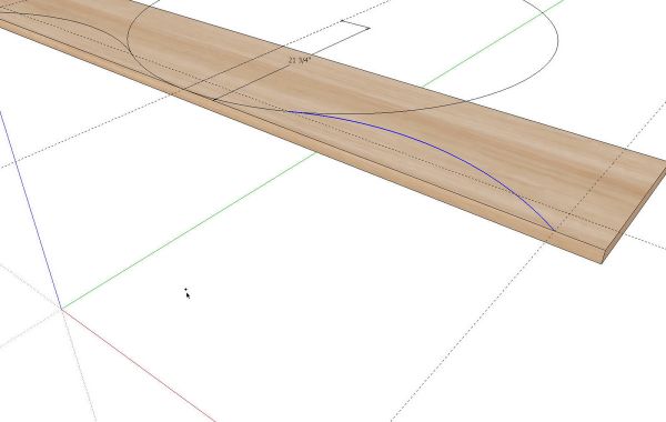
Now, while these last two curves are still arcs, we can find their centers. Right click on the arc and choose Point at Center. A guide point will be placed at the center. If you wanted something more durable than the guide point, you could draw a couple of lines that intersect on the point.
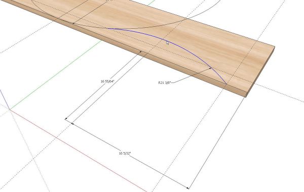
You could also add dimensions if you wish.
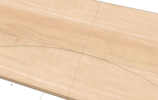
The original question involved locating the narrowest part of the shelf so in the image above, I’ve dragged a guideline in from a long edge to find the high spot in the arc. Then a guideline parallel to the end of the board extends that intersection to the front edge.
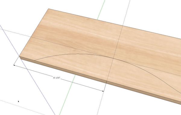
And now we can locate that point with a dimension.
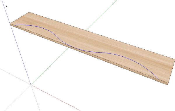
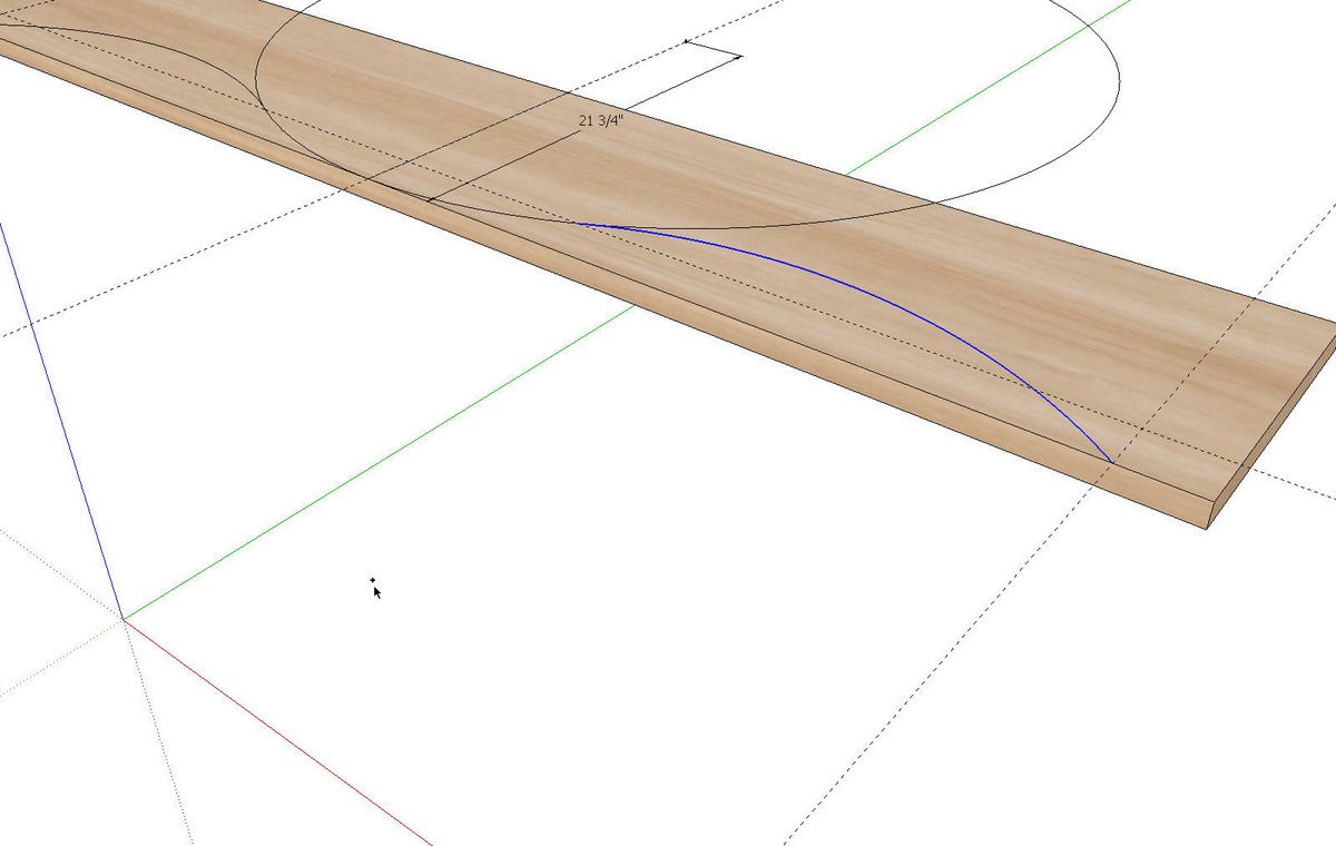
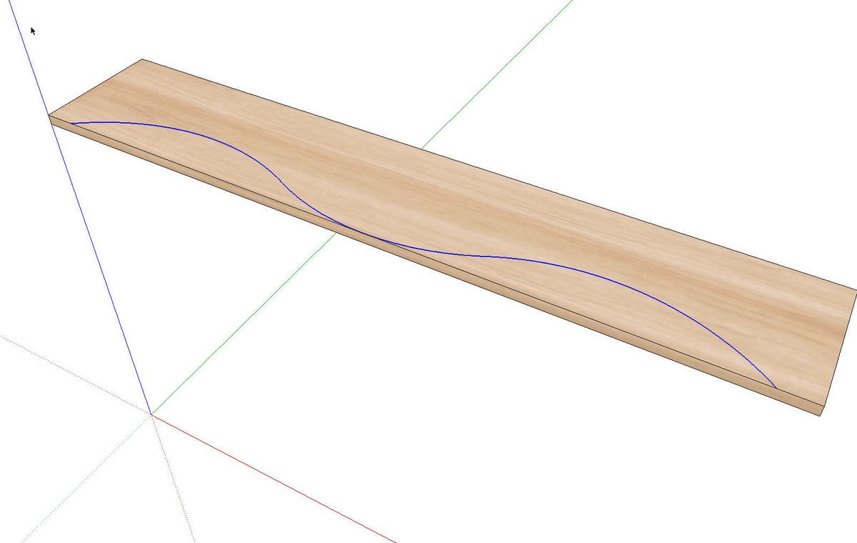
Suppose we want to go ahead and modify the component with the curve. Delete the unneeded part of the circle. Select the three separate arcs and weld them together with Weld.rb. With the entire curve selected, click on Edit>Cut, the Cut tool, Ctrl+X or Command-X. The curve will disappear but don’t panic. Open the component for editing. You can do this from the Context menu but I find double clicking on it with the Select tool faster.
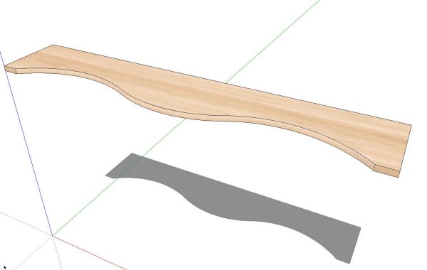
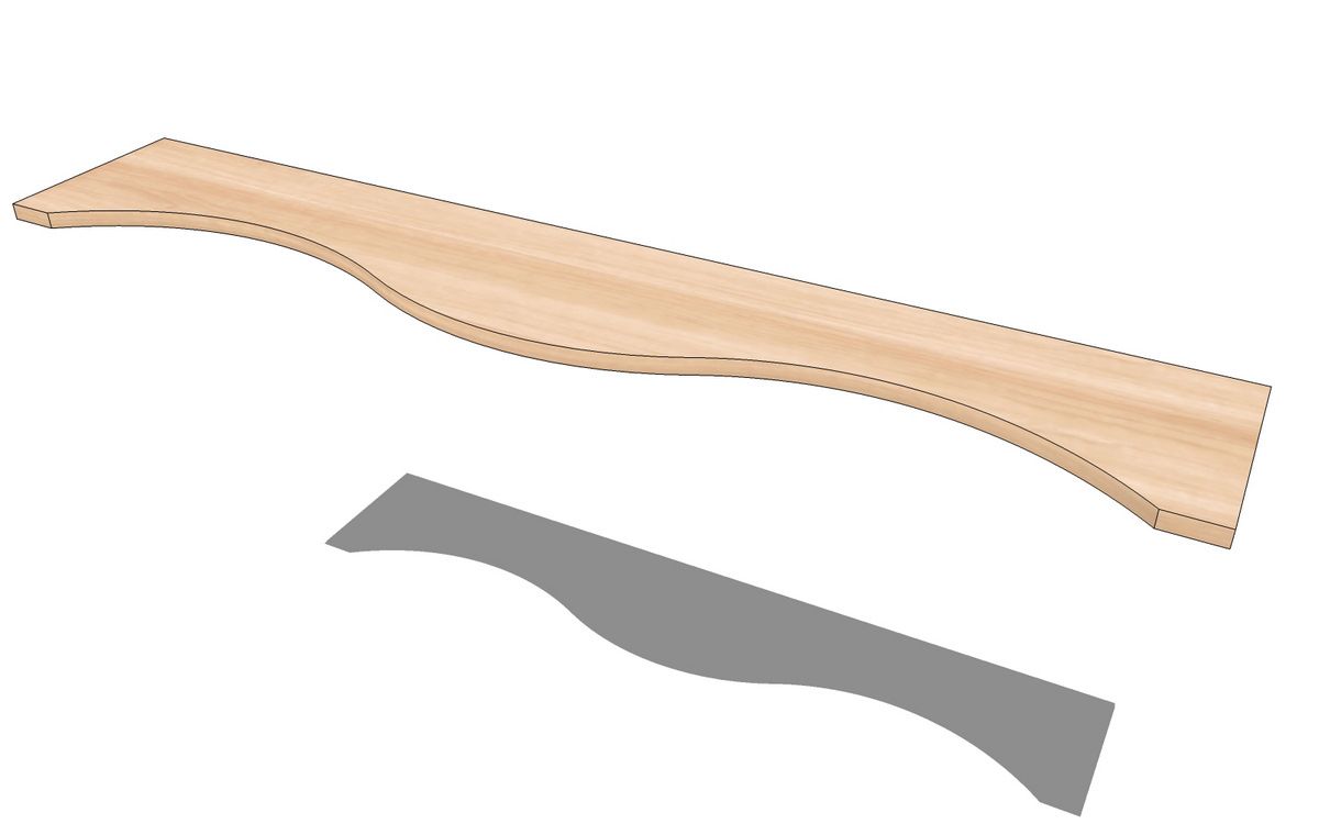
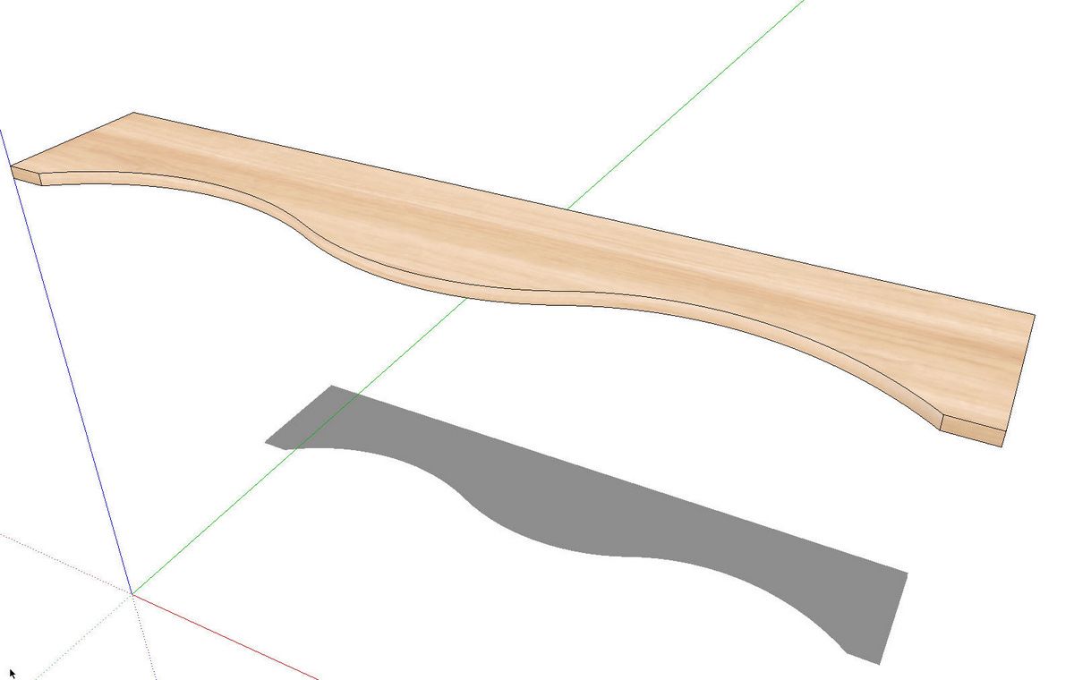
Now click on Edit>Paste in Place. the curve will now be part of the component. Push/Pull will finish up cutting the wave shape.
I normally wouldn’t have materials applied at this point but I wanted to show one more thing. I used a different material on the front edge of the shelf than I did on the top. After the Push/Pull operation, the material on the wave surface is the top material. I want to restore the front edge material. With the component open for editing, I right clicked on the straight part of the edge at the end of the board. I chose Texture>Projected. then I used the eye dropper from the Materials browser to sample that material and clicked on the wave surface to apply the material. In this small image the difference is subtle but it is different.

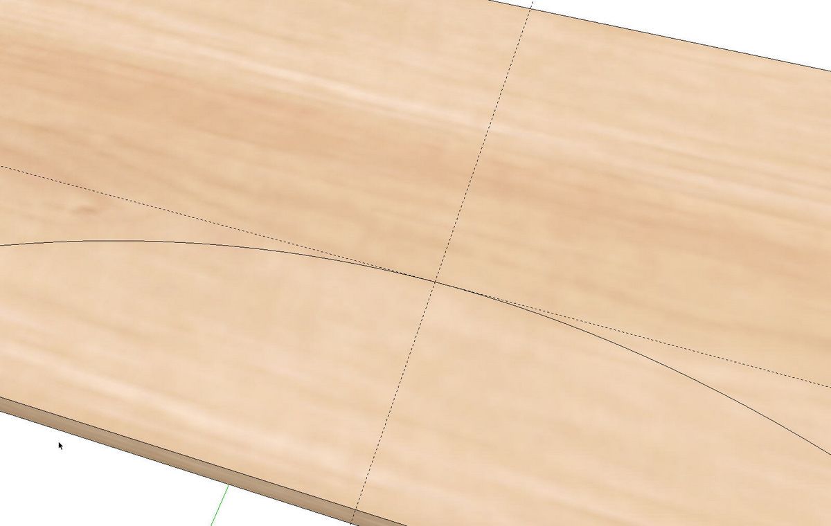
Even if you use the same material on the top and front edge, you may find that you need to modify its position on the wave. You can use the same process.
Note that you won’t have this option if you’ve applied the material to the component instead of the faces.
Hopefully there’s something you can use in this for your work.
Happy Holidays.



Comments
A terrific tutorial, as usual. The technique would also apply to shaping serpentine drawer fronts and drawer dividers in a chest or secretary, or even a curved-front sideboard.
Dave is possible to get the plugin wudwork-wwxmnt download set up in a video. This would help.
Thanks
Ray
cataline4738, I'm not certain what you are asking for. Could you clarify?
Dave
Log in or create an account to post a comment.
Sign up Log in