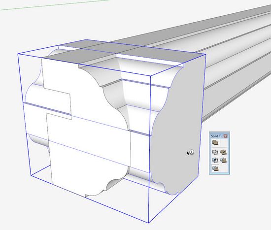
I’m working on a reproduction of a Pennsylvania Dower Chest and have enjoyed experimenting with the new Solid Tools that are a part of Pro version 8. The same results can be achieved with the free version using standard Intersection features.
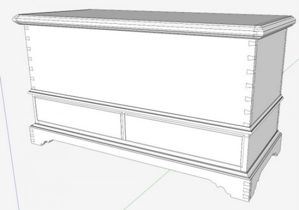
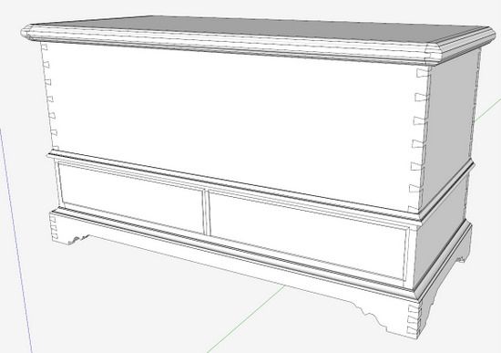
Here is the overall assembled model of the Dower Chest.
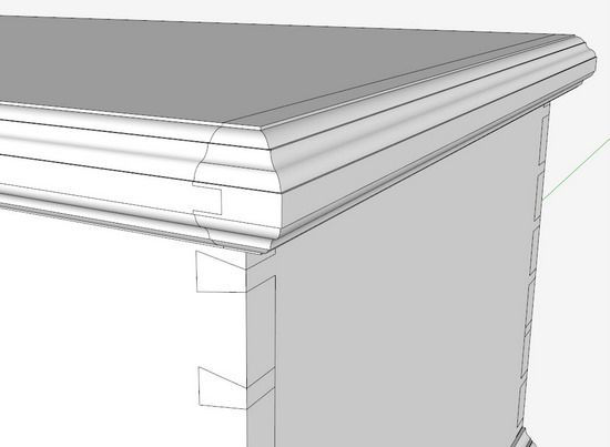
And here is a closer view of the molded top pieces.
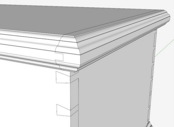
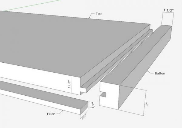
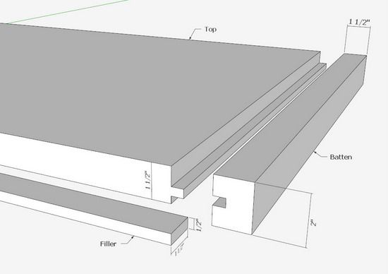
The molded Top is somewhat unique consisting of three separate components including breadboard ends (or battens). It is also 2-in. thick. The middle Top piece is 1 1/2-in. thick, so a separate 1/2-in. Filler piece is added to the underside of the front edge of the Top. All of these pieces get a molding treatment. Here is the Top assembly exploded.

Note the elaborate shaping (molding) of the front and side edges. There are no miter joints in this construction, but the breadboard ends (battens) will require shaping on both the front and side faces. I’ll show steps of one method to create these shaped parts.
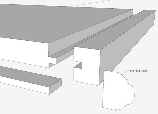
Step 1: The rough parts are created with the Line and Push/Pull Tools. Create the tongue and groove joint in the Breadboard ends. This would be the same procedure I plan to use in the shop.
Step 2: Create the profile shape for the molding. I was able to import a picture and trace over it to create a face that approximates the original.
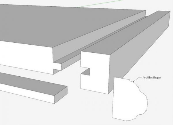
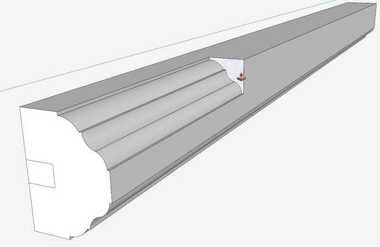
Step 3: After pasting the profile on the end of the Batten, I used the Push/Pull Tool to shape the side face.
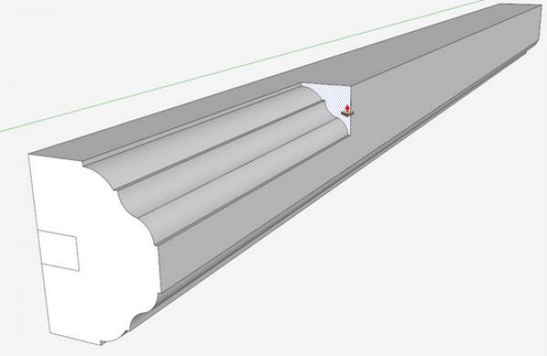
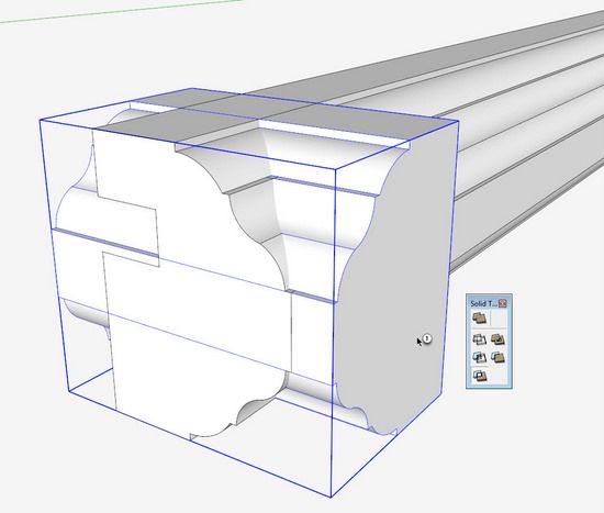
Step 4: Now it gets a little complicated, since we need a perpendicular shaping across the front end of this Batten. I rotated the profile shape and extruded it a couple inches in length. Then I chose the Split Solid Tool from the Solid Tools Toolbar shown below. The Split Tool is the very bottom icon in the list. When used to intersect solid groups, it keeps all the results in the model.
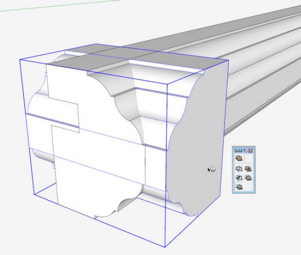
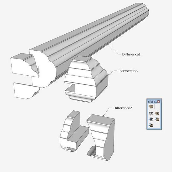
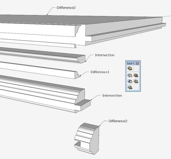
Step 5: After “splitting”, the results are shown in three different groups, the Intersection, Difference 1, and Difference 2. By inspection we can throw away Difference 2, trim off the two segments that are part of Difference 1, and paste the Intersection to the end of the Batten.
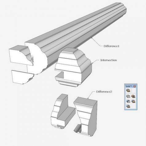
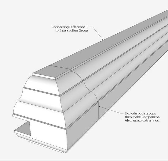
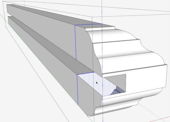
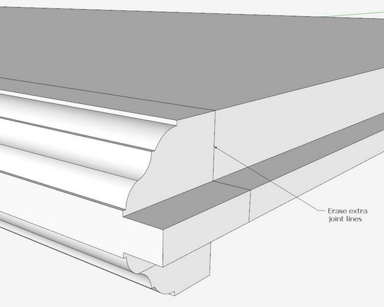
Step 6: Combine the two parts to complete the Batten component. However, there is a joint face that should be removed, shown below.
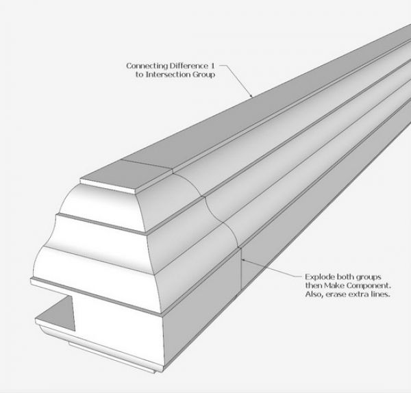
To remove that joint line and face, you can do a tedious removal on the surface of the shape, but this takes quite a bit of time. A quicker way, is to hide an outside face to expose the inner face. Then double click on inner face and hit the Delete Key. This will remove all that offending joint line.
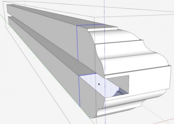
Step 7: Now we need to shape the other two parts of the Top. Use the profile again and Push/Pull it across the front of the Top piece and the Filler. Pick the same Split Tool from the Solid Tools Toolbar and click it on the Top and the Profile extruded group.
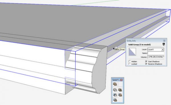
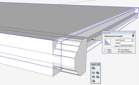
By the way, Solid Tools requires that the groups or components be created with perfection – no extra lines or anomalies. A quick way to check whether your groups or components will work OK, you can check the Entity Info of the group or component. As shown below, the Entity Info dialog box tells you by the identifying words, “Solid Group” (__ in model). If it says only “Group” or “Component” without the word “Solid”, there is a problem and Solid Tools won’t work.
Step 8: After using the Split Tool, you end up with several parts shown below, and many of these parts can be thrown away.
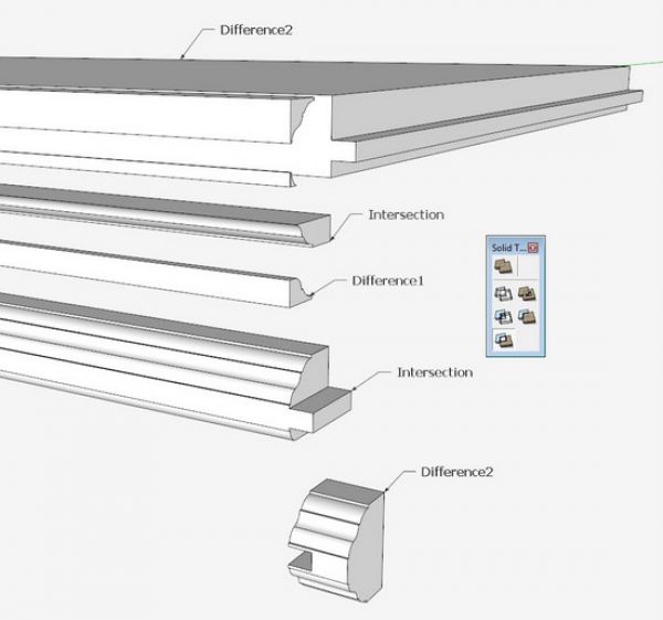
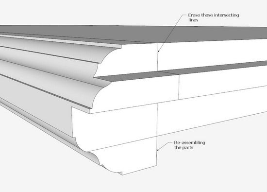
Step 9: Re-assemble the parts as shown below. Again there is a joint line that must be removed. This can be easily done with the Eraser with a few clicks.
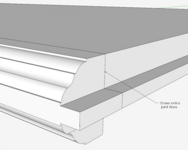
This completes the shaping of the Top pieces. An alternate method of shaping could be with the Follow Me on a single group or component. However, there will be some work and intersections required to pull the pieces out of the shaped whole.
Again using Intersection in the Free version, the same results can be obtained without Solid Tools and the Pro version.
In the shop, I will glue up the rough components (without shaping). Then I will create the shaping on the assembled whole.






Comments
Well done article. Thanks.
Great job!
I think another simpler way to create the shaped batten is to use the FollowMe Tool. Put the profile shape in a corner of the rough batten (i.e. the bottom left one in your picture) then highlight the profile you want to follow (the external profile of the batten) and finally click the FollowMe on the profile shape: you will get the profiled batten in four click!
giovanni
To rocknbike: You are right. There are always several ways to do something, and I sometimes pick the harder one.
Thanks,
Tim
Log in or create an account to post a comment.
Sign up Log in