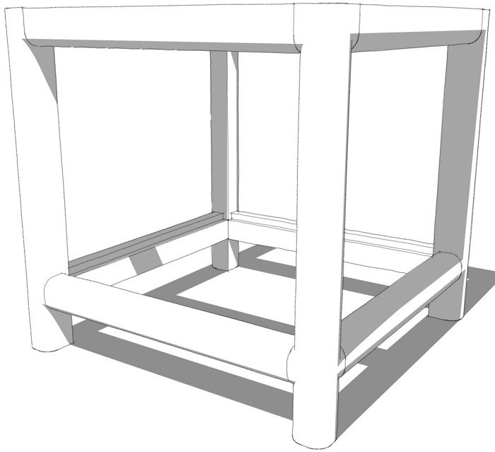
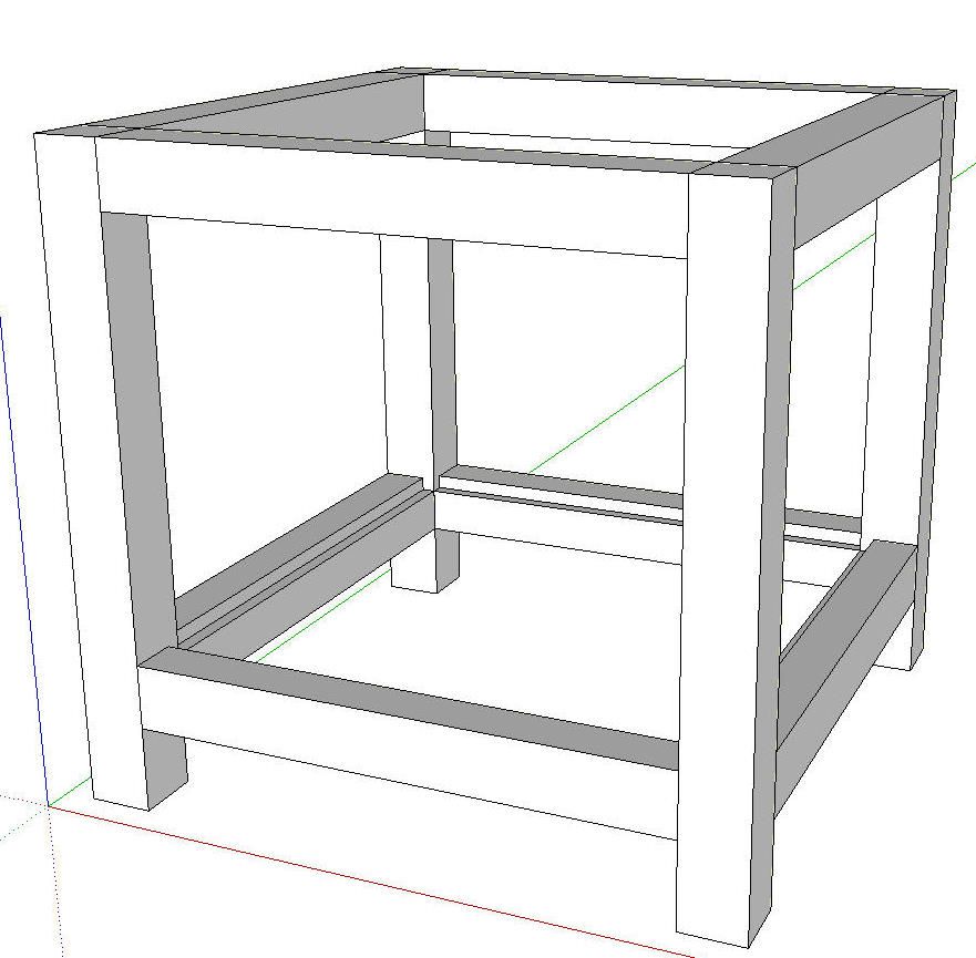
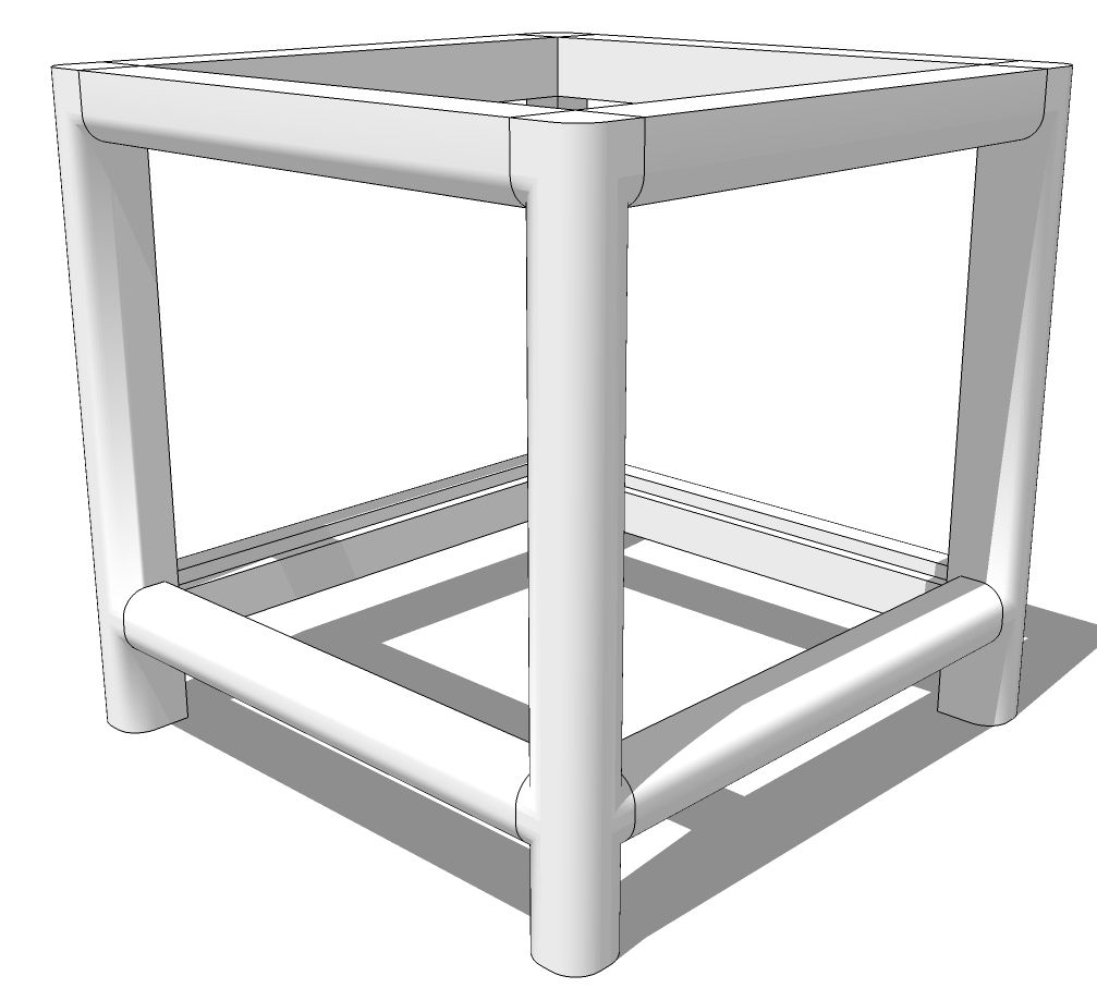
One of our readers contacted me today asking for a suggestion on how to draw radiused edges on components when those components meet. The example he used and which I am using for this demonstration, is a base for a table which has stretchers and aprons meeting the legs. In the shop, he plans to assemble the parts and then run a large round over cutter around the edges.
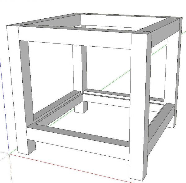
In this example all of the stretchers and aprons are the same length. They are instances of three different components. The front left leg was drawn first and made into a component. It was copied with Ctrl+Move and then the copies flipped (mirrored) so the corresponding faces are facing each other. Keep in mind flipping is not the same as rotating the components. Although they make look the same at this point the end results will be different if the components are simply rotated. It is important that we use components for these parts and not groups. If you use groups instead, you can plan to work harder.
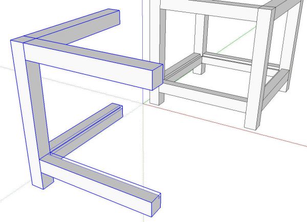
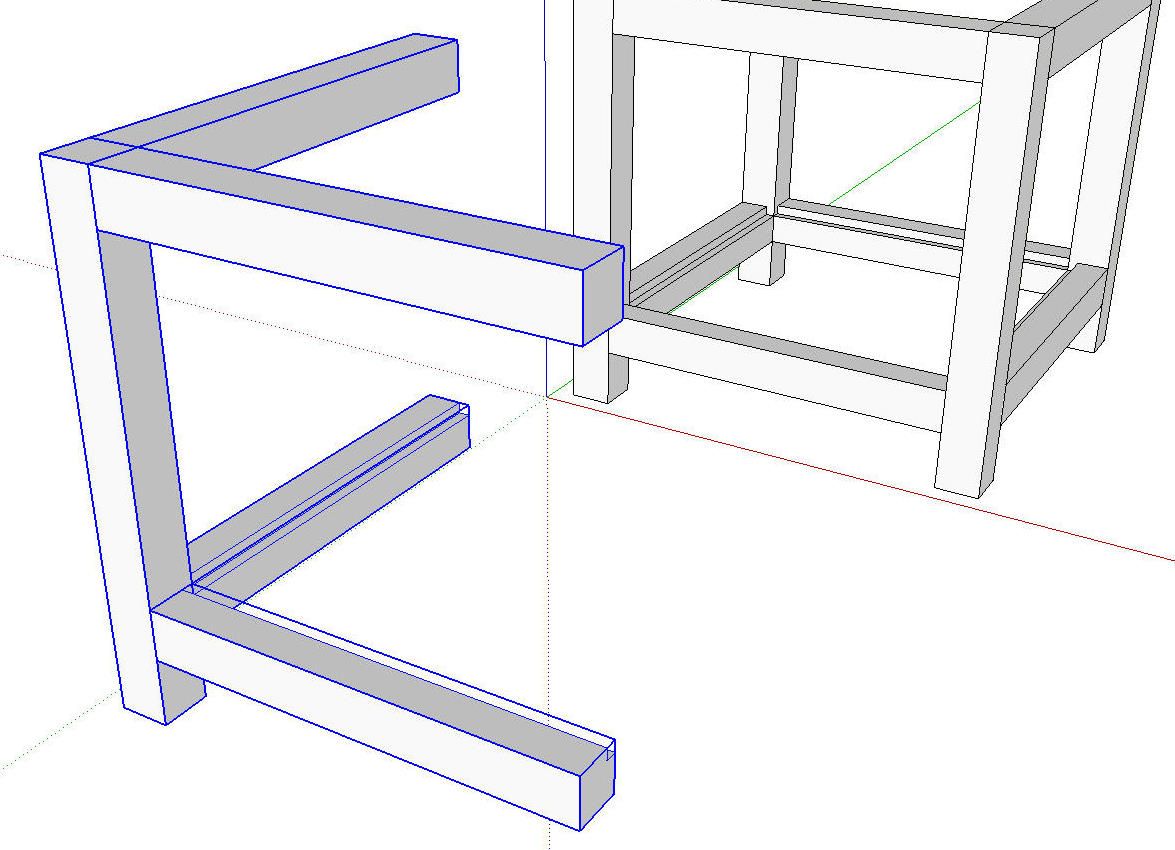
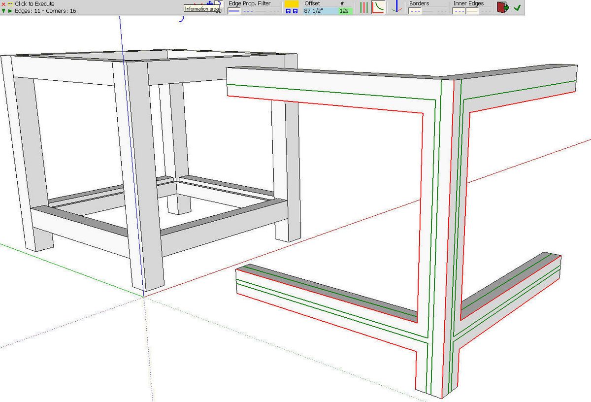
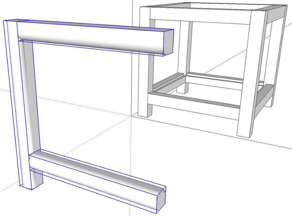
I selected a leg and the adjoining apron and stretcher components and copied them out away from the rest of the model. While they were selected, I right clicked on them and chose Explode. This explodes the components and turns these parts into one big lump of geometry.
In anticipation of the rounding over step I scaled the model up by a factor of 100. This was done because I expect the rounding over process could generate some tiny faces which SketchUp won’t fill in. By scaling up before doing what it is that will create those tiny faces, we avoid the holes.

I started the Round Corner plugin and set the Offset to 87-1/2 in. The round over is to be a 7/8-in. radius and since we’ve scaled up by a facotor of 100, this should give us the right radius.
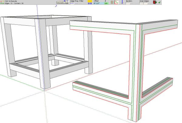
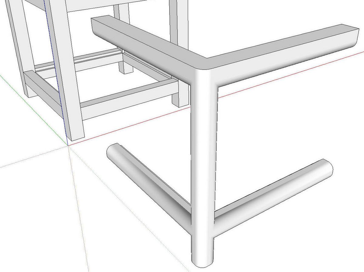
Next I selected the edges to round over. I did not select the edges on the inside corners where the legs and rails meet. Then I hit Enter.
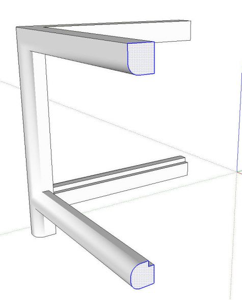
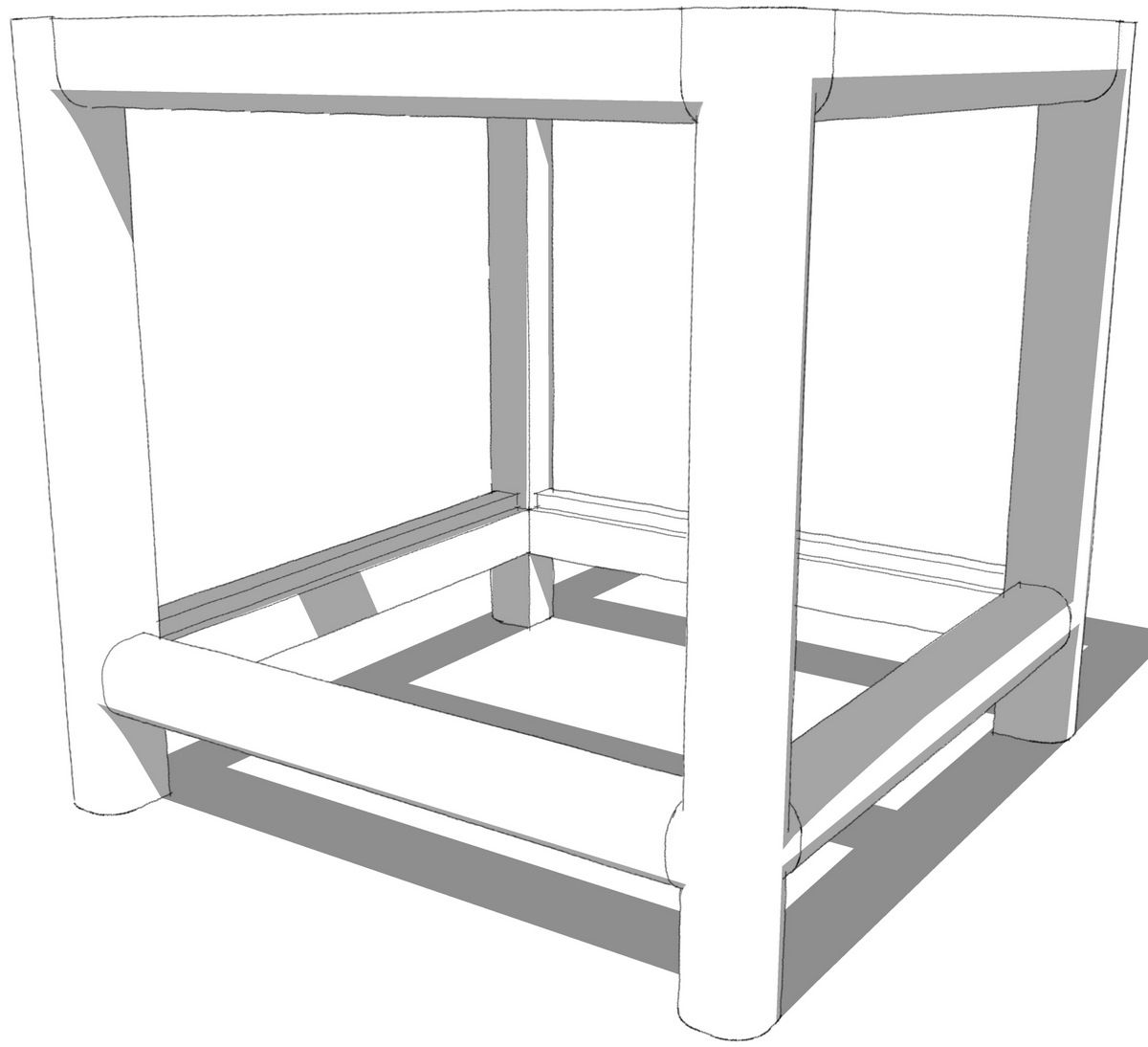
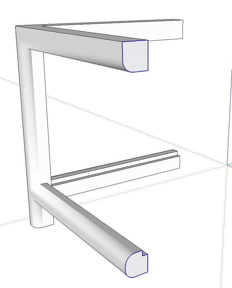
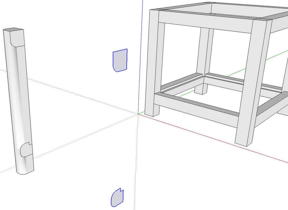
After the edges have been rounded, I selected the faces at the ends of the front apron and stretcher. I clicked on the Copy button on the toolbar. Or Ctrl+C (Command-C on the Mac) or Edit>Copy. Then I used Push/Pull to push the faces of both aprons and stretchers up to the leg.
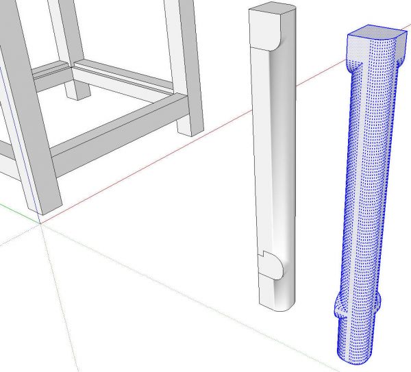
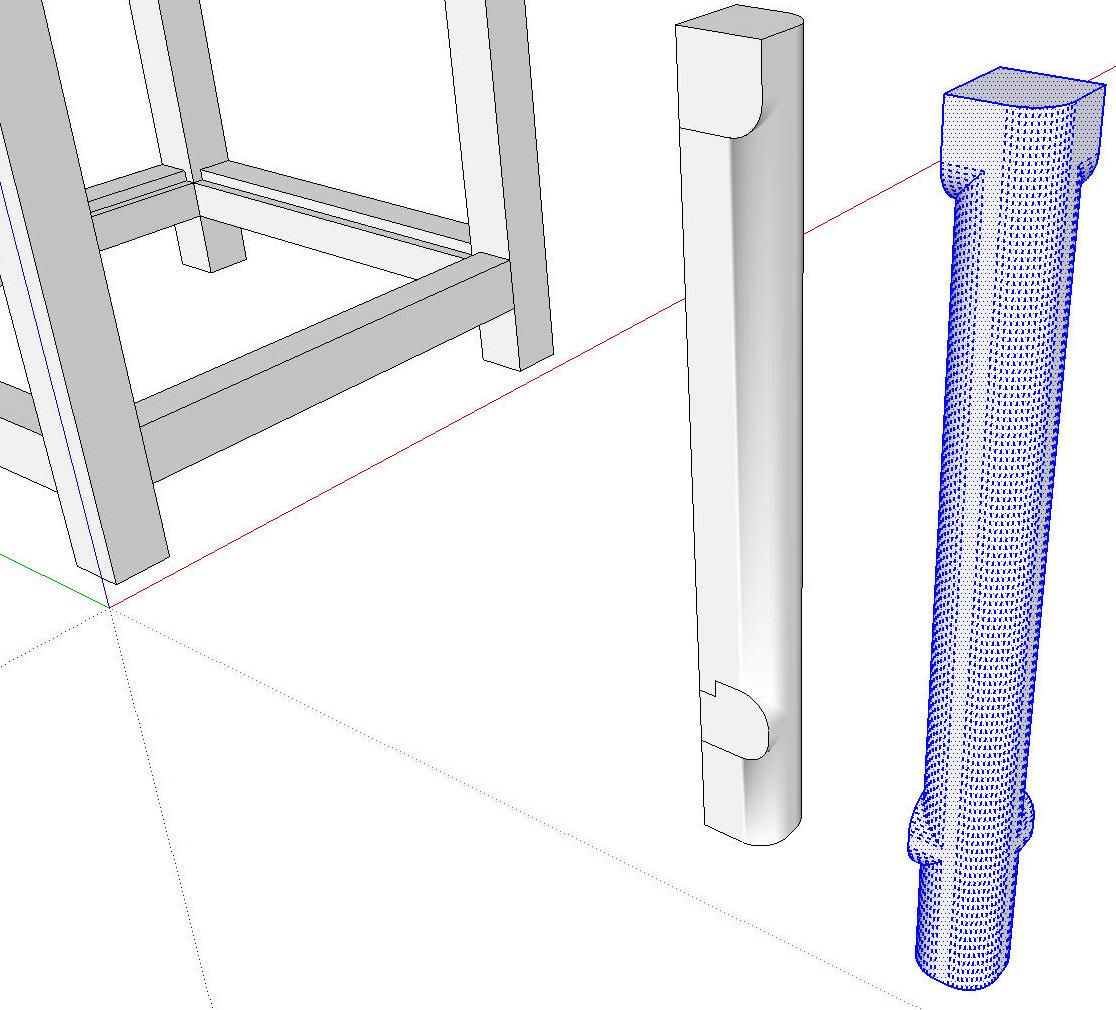
We now have the shape of the leg. I made a copy and rotated it just to be able to show it from two directions but you wouldn’t normally make that copy.
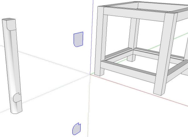
This next part is easy but you must do things in the right order for it to work right. At this stage I have the leg as loose geometry. It is not yet a component. I click on Edit>Paste in Place to place those faces I copied before. These faces are located at the right end of the apron and stretcher. Next I scaled the model back down to proper size. Then I make a component of the rounded leg. Do not make the component before scaling down as this will cause problems due to the size. Although I don’t show it, I also delete the coplanar edges on the flat faces of the legs.
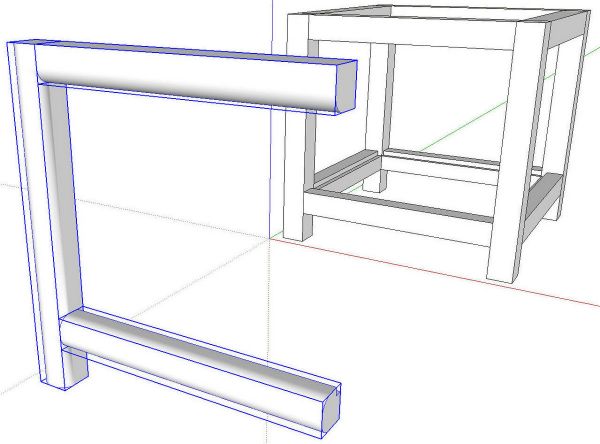
I welded the curves on these faces and then used Push/Pull to extrude them to the leg. I make each of these a component.
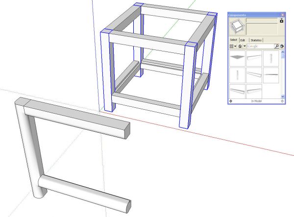
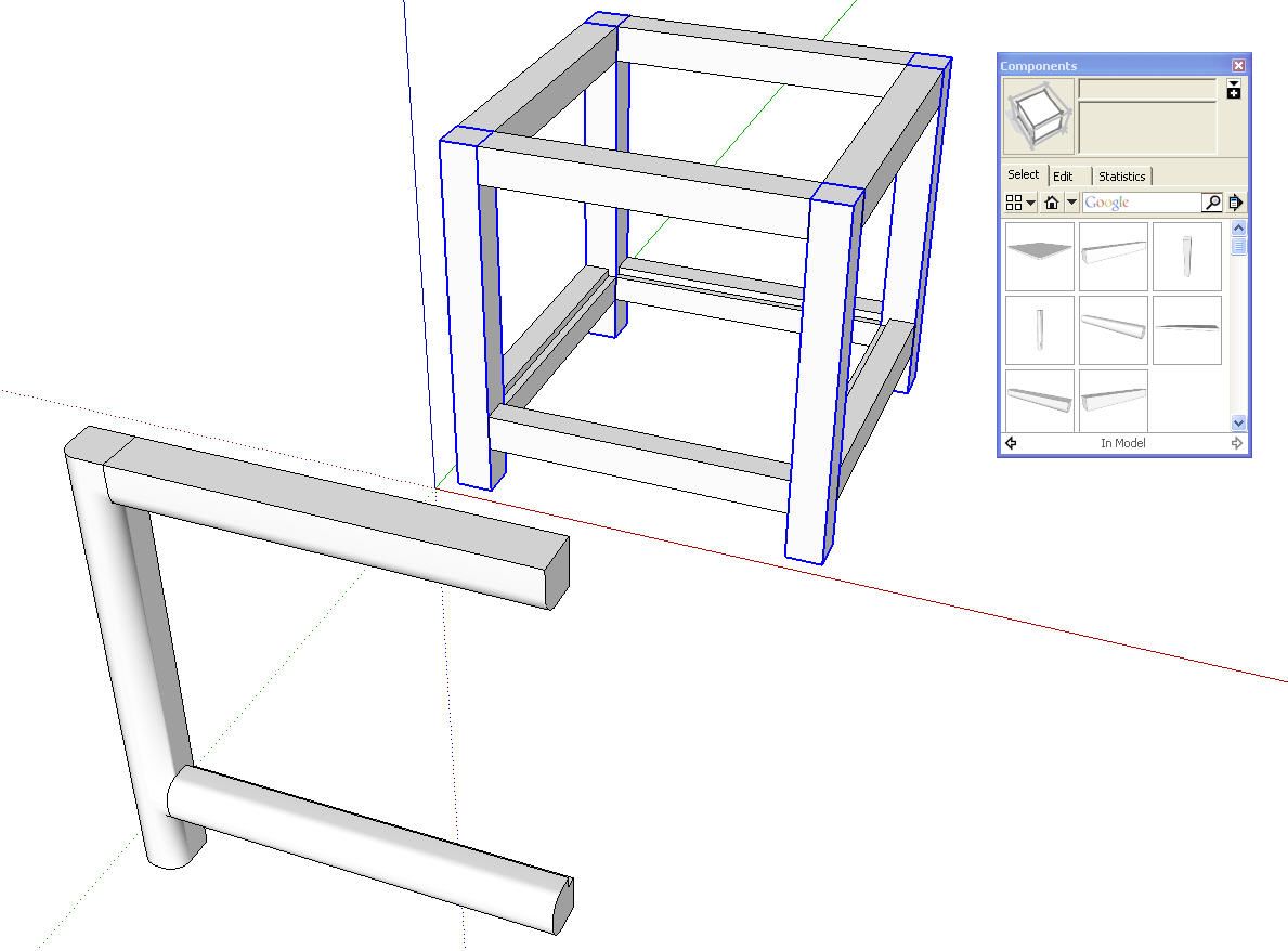
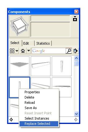
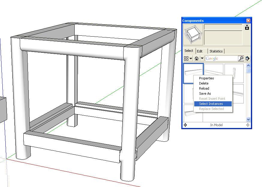
Now it is time to replace the original parts with the new ones. Open the Components browser under the Window menu. Set it to the In Model library. In the above image I’ve selected the legs. That can be done manually or by right clicking on the component thumbnail in the browser and choosing Select Instances. Then right click on the thumbnail for the new leg and choose Replace Selected.
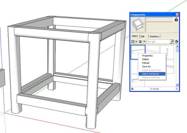
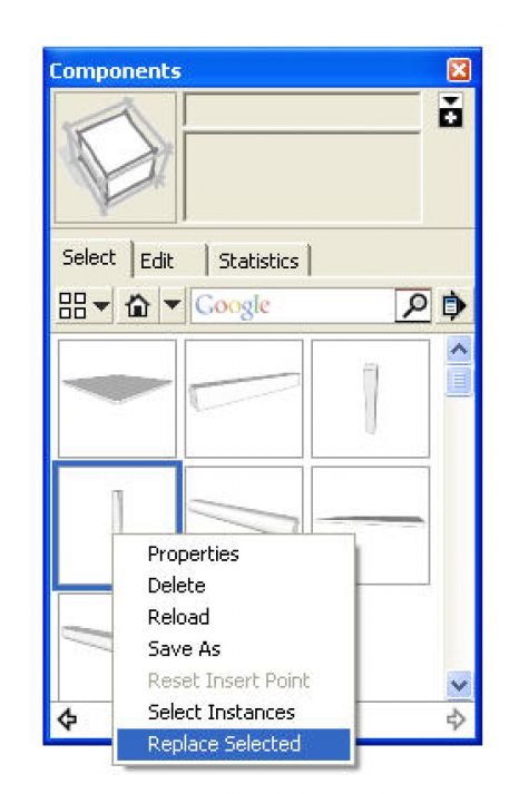
Repeat that process for the rest of the components and you’d finished.
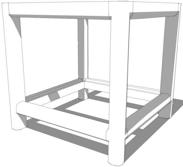
You could use Shift+Eraser on the edges at the joints to hide them if you wish. You can also edit the components to add the joinery if needed.
Some of our astute readers will discover that the round overs aren’t exactly accurate in the corners where the router cutter changes direction but that detail would be very tiny and not really visible. It is possible to draw the corner curves but it would take more time and more set up and I doubt the investment would pay off in most cases.



Log in or create an account to post a comment.
Sign up Log in