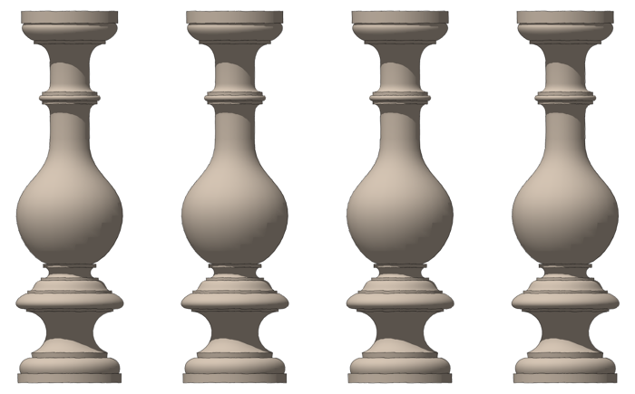
Once in awhile it happens that you want to draw a SketchUp model from a sketch on paper. Perhaps it is something you’ve drawn out by hand or as in this example, it’s from a an old book published in the 1940’s. You might be able to work out enough details to draw it from scratch but if the shapes you need are intricate, you might try tracing the original right in SketchUp. If you go about it in an orderly fashion, it is actually quite simple to do.
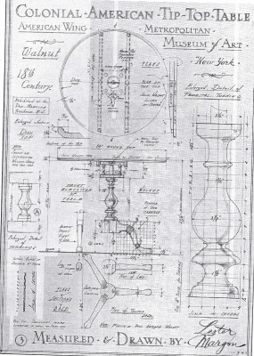
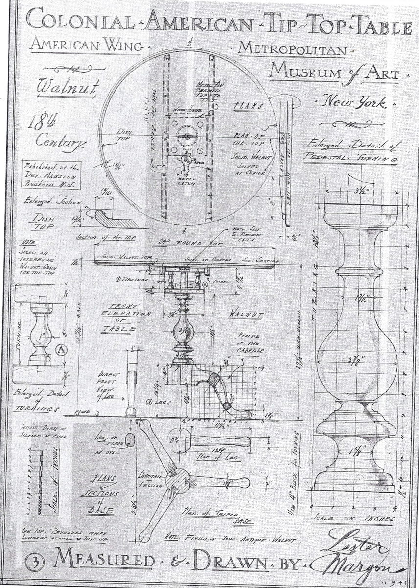
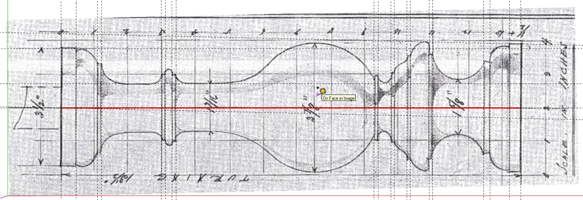
For this example I’m going to draw the column for this Colonial American Tilt Top Table. The page was scanned and sent to me as a PDF file. At this point I’m only interested in the colum and I don’t need the rest of the page. I opened the file in Adobe Reader and rotated the view so the long dimension of the column is aligned with the long dimension of my computer screen. Then I zoomed in to make the column fill as much of my screen as I could. Then I used the Snapshot tool to drag a box around the column. The snapshot is automatically saved to the Clipboard.
I opened an image editor—I used Paint.NET—and pasted the image. Sometimes the image can do with a bit of clean up. You might want to increase contrast a bit or otherwise tune the image. Then save it as either a JPG or PNG. I prefer PNG because there’s no compression loss although it does result in a larger file size.
Note, in the scan above, the page is angled slightly. We could deal with that in our image editor but I’ll do it in SketchUp instead.
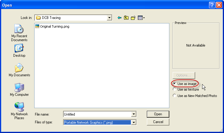
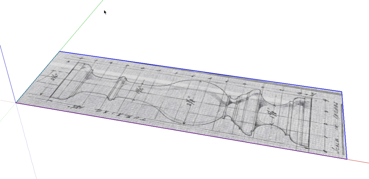
Next, open SketchUp. Click on File>Import. In the dialog box that opens, choose the correct file type and the location in which you saved the image file. Make sure you tick the radio button for Use as image. Choose the image and click Open.
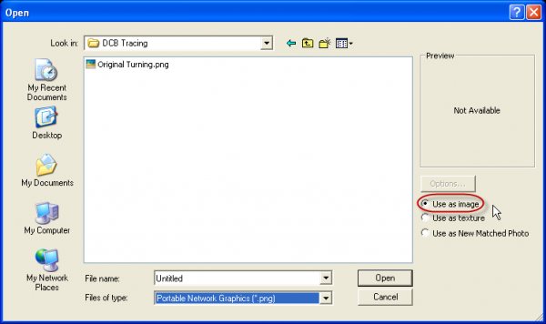
The dialog box closes. Click at the origin and drag out like you’re drawing a rectangle to insert the image. The exact dimension isn’t critical but I like to make it somewhat large.
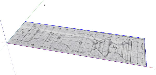
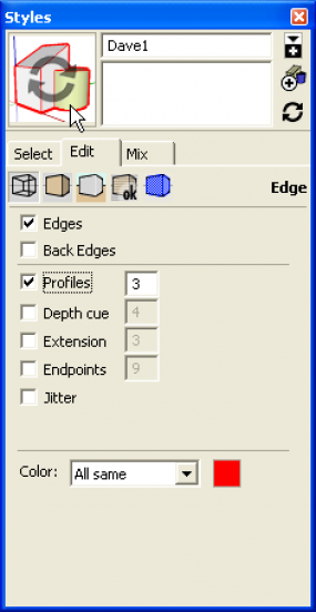
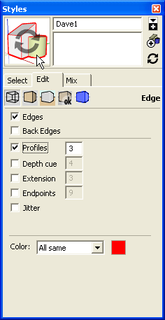
Before doing anything else, I’ll make a temporary change to the drawing style to make it easier to see what I’m doing. I open the Styles dialog under the Window menu and clicked on the Edit tab. I changed the line color to red by clicking on the little square at the bottom of the dialog box near All same. My normal style has Profiles turned on but the width set to 1. For this work I will set it to 3 to make the lines easier to see.
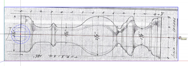
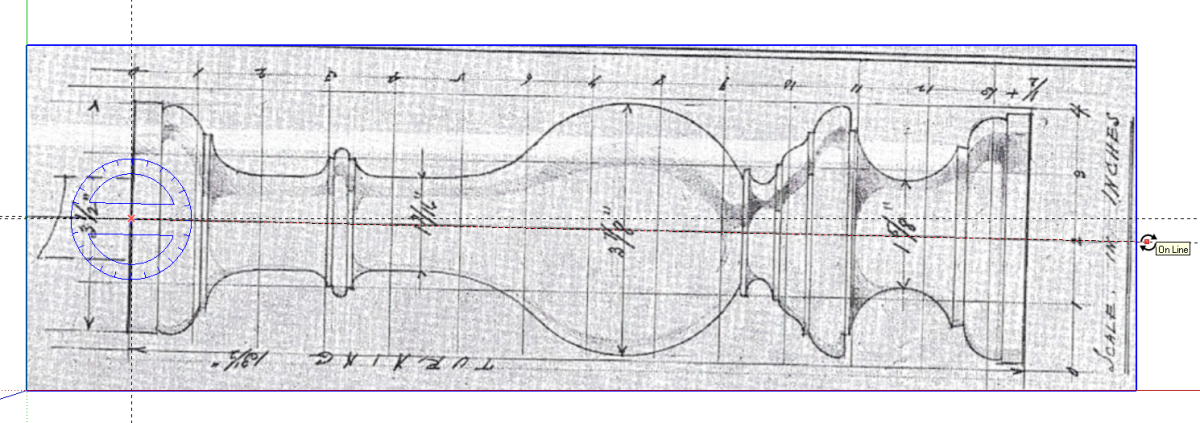
For this example I’ll straighten the image so it aligns to the global axes to make drawing over it easier. I’ll start by placing a few guidelines. I put crossing guidelines parallel to the red and green axes so their intersection is at the top center of the column sketch. I used the yellow Protractor tool to put a guideline down the centerline of the column as well.
The next step is to select the image and get the Rotate tool. Rotate the image about the intersection of the first two guidelines. I set the center of rotation by clicking on the intersection. Then I click out along the guideline on the centerline of the sketch and finally click on the guideline parallel to the red axis.
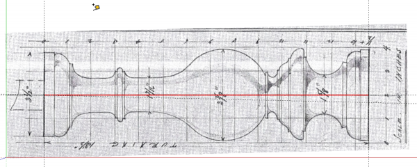
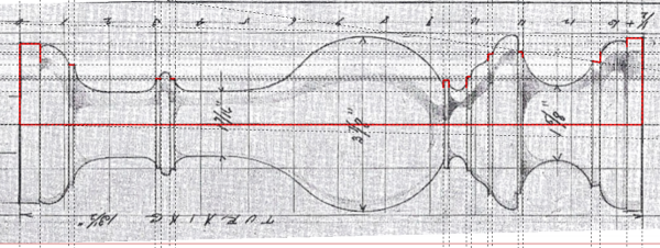
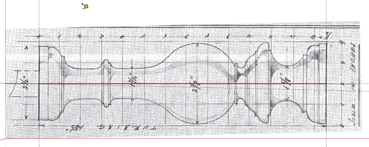
After rotating the image, I added a guideline at the bottom of the column sketch and then drew in the centerline with the Line tool. With that centerline drawn in, I get the Tape Measure tool and measure the line making sure to click at both ends of it. The Measurements box in the lower right corner displays the measured length. The column is supposed to be 13-1/2 in. long so I typed in 13.5 and hit Enter to resize it. I’ll scale it up before I start tracing but by working at full size, I can easily check to see that the image is scaled correctly in both directions without having to do any math. Since the drawing is done by hand, it’s not unlikely that there’s a scaling issue although in this case, the drawing is pretty good.
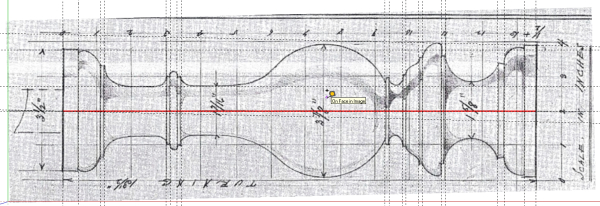
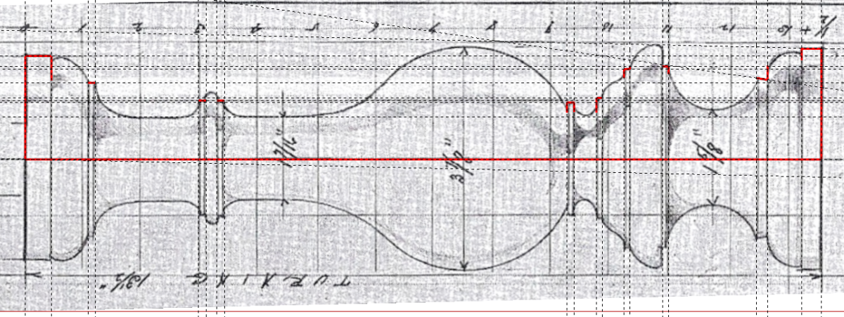
The next step is to add some guidelines marking out the major points along the length of the turning. I think if this as similar to marking out lines on a turned blank with a pencil before diving in with a tool. Since I’m working at full size, I can also check distances along the length as I go.
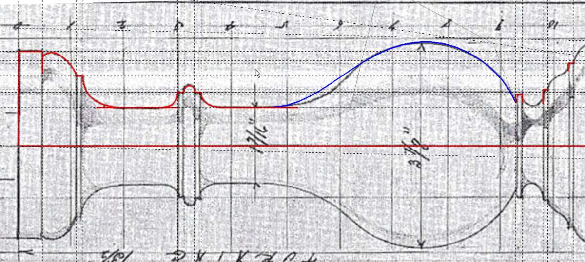
Next I’ll scale the entire model up by a factor of 100. I do this by using the Tape Measure tool to measure the centerline as before. This time I type in 135 and hit Enter. Then it is time to start tracing. I like to draw in all the straight lines before working on the curves. The straight lines give me start and end points for the curves and I’m not switching back and forth between tools.
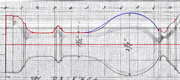
With all the straight lines drawn in I switch to drawing the curves. Some of these curves like the bead on the necked-down area and the cove below the bulge can be drawn in with the Arc tool. For the rest of them I used the Bezier plugin. The way that plugin works you may sometimes just need to get the curve drawn and then edit it afterward the blue curve is in Edit mode and with a little tweaking will fit the bulge just fine. You could do all of these curves with the Arc tool but most of them are not circular arcs so they would require a lot of fussing to get right. Even with editing the Bezier curves it goes pretty quickly.
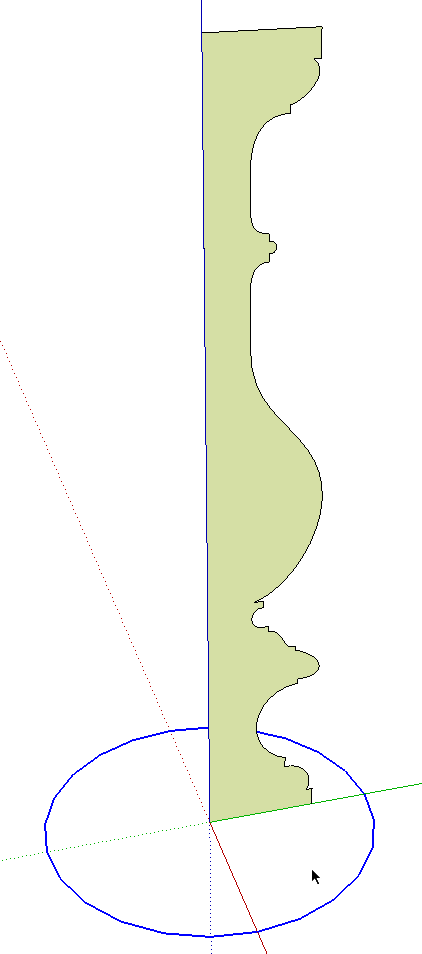
When the final curve is filled in, a face should be created as seen below. If the face is not created, go hunting. You’ve either got a gap or a line segment is not on plane with the rest.

Now we’re finished with the sketch and the guidelines so they can be deleted. That’s pretty much all there is about the tracing business. Sometimes the drawings you have aren’t that great. The lines are fuzzy and perhaps the drawing has not been scaled correctly in both directions. In the case of fuzzy lines, try zooming out a bit to make the lines appear thinner. In the case of bad scaling, you might be able to scale the original sketch with the Scale tool. sometimes that works but I’ve also found cases where a drawing just couldn’t be adjusted to work properly. In those case I pick a dimension and then use best guess, dead reckoning and seat of the pants to fill in the unknown stuff.
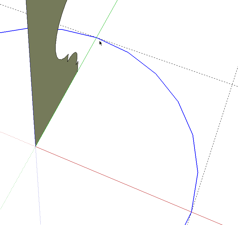
Since we have the profile of the column drawn, we might as well make it 3D. I put the original sketch on the ground plane but the column is to be used vertically so I rotated the face up into the correct orientation. I also moved it to the origin. this isn’t a necessity but the origin is a nice reference point for the upcoming operations. I’ll be using Follow Me to create the turning so I’ve drawn a circle centered on the centerline and origin. Notice that I’ve also deleted the face of the circle. there are two reasons for this. First, since the column profile is standing on the ground plane and the circle is drawn there as well, If we run Follow Me, the bottom of the column will not be created. The other reason is that I’m going to rotate the circle a bit and if I left the face, the rotation would distort the profile.
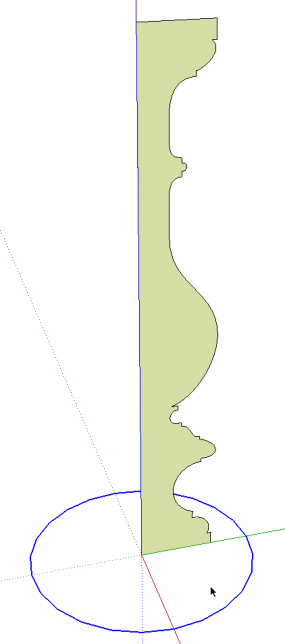
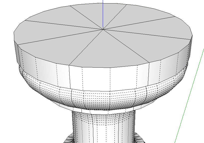
There are a lot ofentities (line segments and the face) in the profile and, if I run Follow Me all the way round the circle, the entity count will increase quite dramatically. I prefer to keep the file size down by leveraging the use of components so I’ll only make a portion of the turning and make copies to complete it. In order to make the turning look like a smooth single component when I am finished I need to do a few things. I’ll end up using only 45° of arc for Follow Me and I want the ends of the extrusion to be at 45° to each other. If I used a standard arc or simply cut out a chunk of the circle, the start and end segments wouldn’t be at the proper angle. And once the copies were made, there would be hard shadow lines at the seams. So, I’ve drawn the circle as I always do by dragging the radius out on axis. I used the default 12-sided circle.
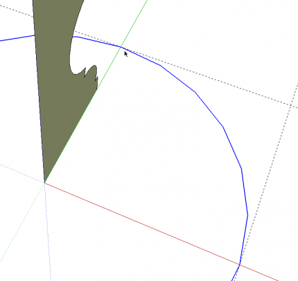
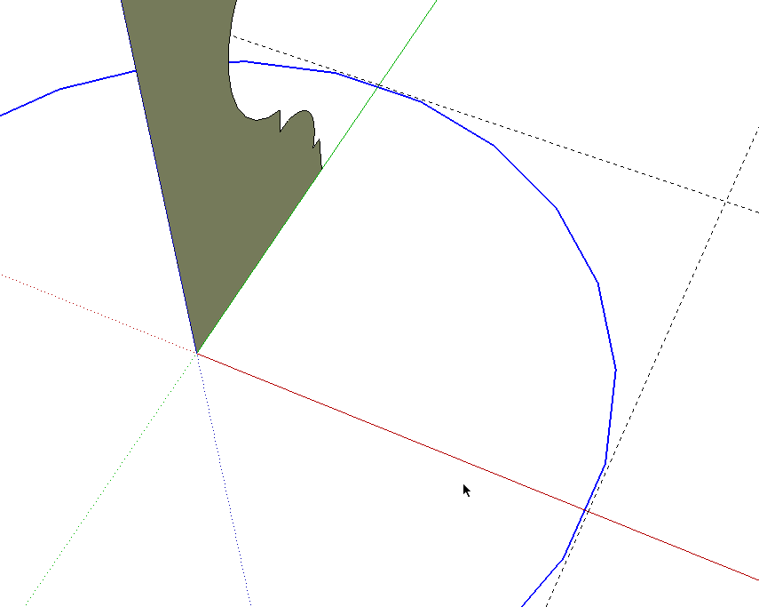
I selected the circle and rotated it 7.5° about its center so that a side is aligned at 90° to the profile.
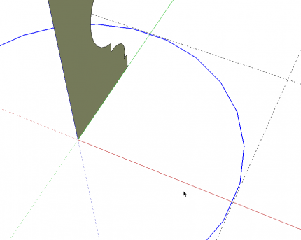
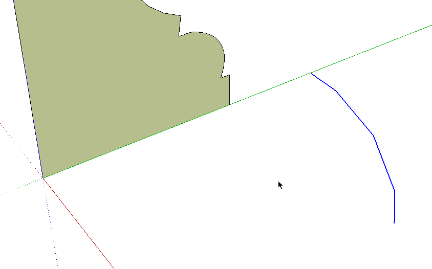
Then I drew some short line segments at the midpoints of two of the sides 45° apart. I deleted the rest of the circle and then those two short ine segments leaving just the short bit of arc. Select the arc, get the Follow Me tool and click on the profile. Presto! a wedge of a column.

The arc can be deleted. Next we’ll scale back down to the proper size. Get the Tape Measure tool and measure the centerline again. Type 13.5 and hit enter. Then delete the vertical centerline and make a component of what’s left. Don’t make the component before resizing. If you save the component for future use, when you bring it into other models, it’ll be too large because the definition will have been written at that larger size.
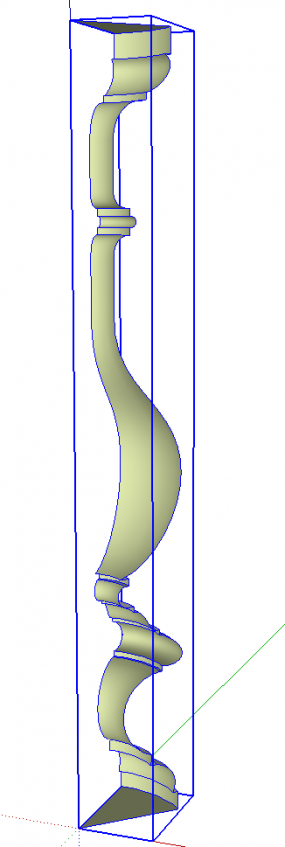
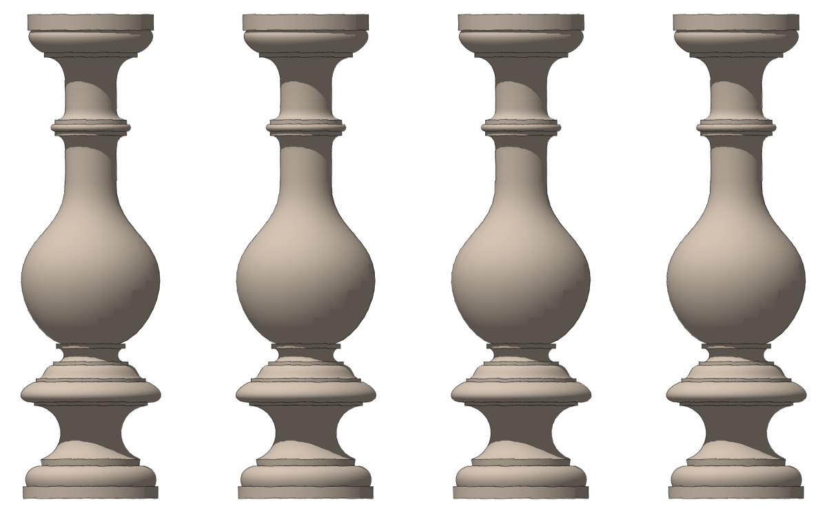
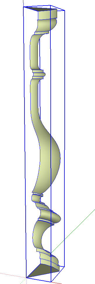
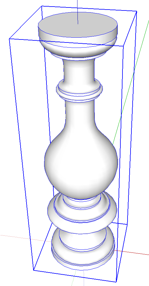
Use the copy function of the Rotate tool to make a radial array with 7 additional copies of the wedge of the column. in the next image you can see the seam lines fall on the flats. We’ll hide those and have a nice, smooth column when we get finished.
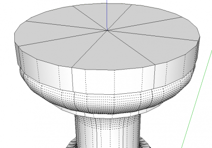
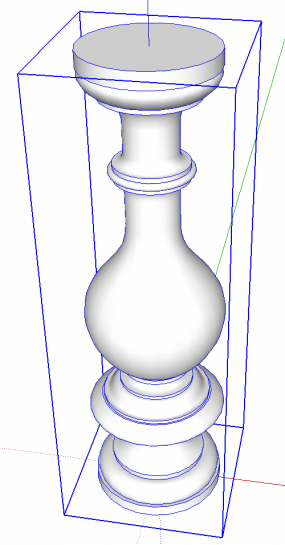
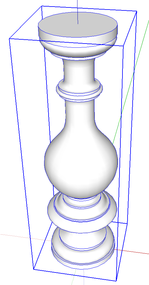
Open one of the components for editing and run the Eraser tool down the seam lines while holding Shift. Select all of the instances of the component and make a component of them and you’re finished.





Comments
Dave,
as usual, this blog reveals your mastery of this medium.
And, as usual, I would have made the mistake of 'turning' the entire column with FollowMe instead of making a wedge, thus increasing the file size!
Thanks for this nice tutorial.
ddwwb
Hi Don,
Thank you. I wouldn't say it would be a mistake to turn the entire column instead of a section of it but making only a section keeps the file size down dramatically by limiting the number of entities.
Here's an interesting experiment to illustrate the benefit of using components in controlling file size.
1. Make a sphere using standard 24-sided circles for both the profile and the Follow Me path. After Follow Me delete the path circle, make a component of the sphere and save the file.
2. Make 100 copies of the sphere component and save the file with a new name.
3. Explode all of the spheres and save the file again with a new name.
4. Compare the file size of each of those files.
Cheers,
Dave
Very nice tutorial Dave!
Luca
For some time now I have been wanting to ask the question how you go about ,just what you describe in this tutorial . Coming from an architectural background I constantly come across plans and architectural details in old books which I want to develop further in Sketch Up. One of the real joys of using SketchUp for me is being able to use the tape measure tool on an imported image once I have resized it , but by sharing the above methodology on this forum , this will allow me to take this aspect of my work to another level .
What a wonderful forum.
Jonas Mac
Jonas, I'm glad to know this helped. Your application is a great one for this. It would be handy for archeological sorts of reconstructions and the like as well.
Dave,
Another very useful article. Thank you.
Chris
Log in or create an account to post a comment.
Sign up Log in