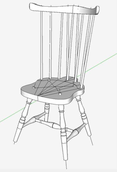
For next semester’s class at Mount Diablo Adult Education Center, I’m developing a model and accompanying design documents for a Braced Comb-Back Side Chair. I like to replicate actual 18th C. Windsors, and in this case I’ve found excellent information in “The Book of American Windsor Furniture” by John Kassay.
In my next few blog posts, I will plan to show the steps I use for this work. So this is Part 1 starting with the modeling of the chair’s seat. (By the way, my modeling process will closely align with the shop work procedure. You start the actual build with the seat.)
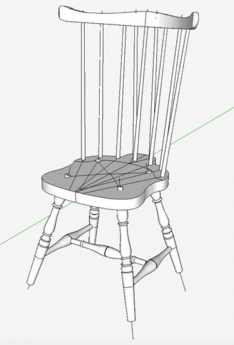
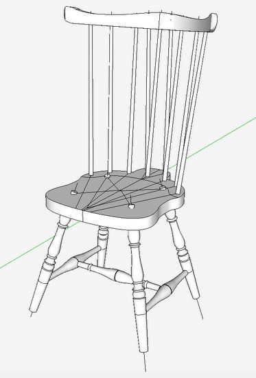
Here is a look at the assembled chair model – it is rough in this stage, without shaping of the seat, but with all the critical information including the “sight lines”. Through the next few blog posts, I’ll show the steps I use to get to this stage of modeling.
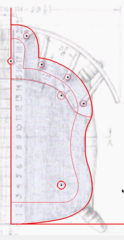
Step 1: Draw out the shape of the seat
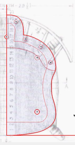
Dave Richards has recently shown a blog post on “Tracing a Reference Drawing” that is applicable to this step. Import the sketch, make it full-size, and trace-over the outline of the seat including location of leg and spindle sockets. The red lines are my tracings, and in X-ray you can see the imported picture of the top view.
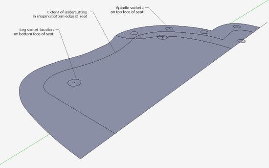
Step 2: Copy the tracing over to a location for building your assembled model.
Note that the socket locations are mixed – that is spindle socket location should be on the top surface of the seat, and the leg sockets are on the bottom face of the seat. At this stage there is only one plane and no thickness.
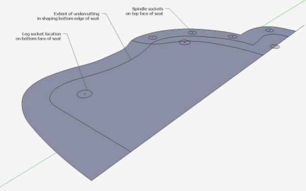
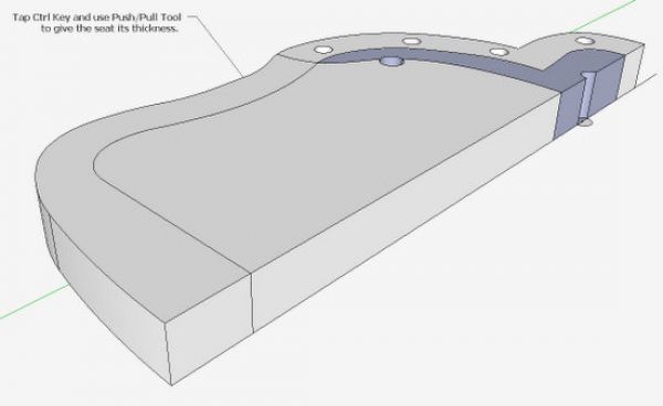
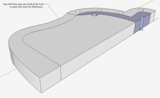
Step 3: Give the seat its thickness using the Push/Pull Tool. You may have to tap the Ctrl Key with the Push/Pull to retain faces on both the bottom and top faces. Some of the sockets will carry up to the top face.
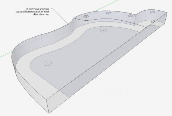
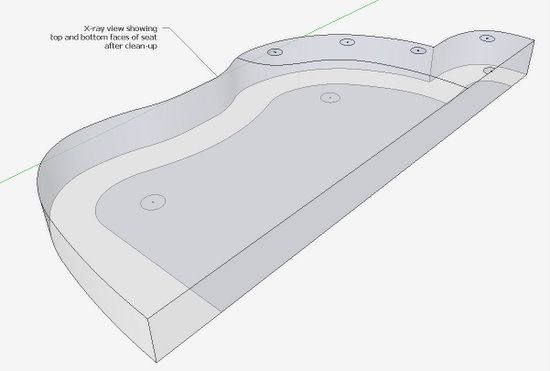
Step 4: Clean-up the seat model making sure to have sockets correctly located on the respective faces. Here in X-ray, you can see the results of my clean-up.
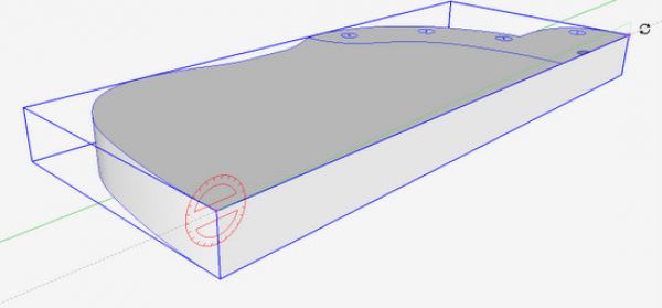
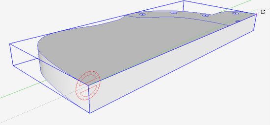
Step 5: Cant the seat at the proper angle – front-to-back. Typically Windsors are 18-in. off the floor in the front and about 17 1/2-in. in the back. Here I’m using the Rotate Tool and rotating around the red axis.
Step 6: Create centerlines for the leg splay
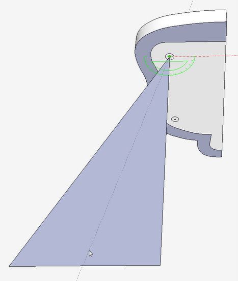
From the center of the socket on the bottom face, draw a line on the blue axis down about 20-in. long. Then continue a line on the red axis and back up to the centerpoint to create a big flat triangle. With the Protractor Tool, create a guideline at the correct splay of the leg on the red axis. Then draw a line from the centerpoint down the guideline and delete the rest of the triangle face.
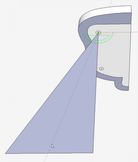
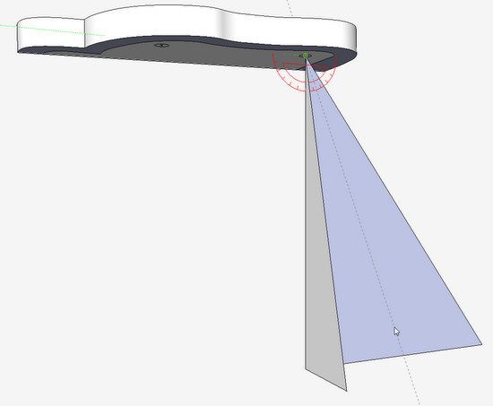
Step 7: Create the splay on the red axis in the same way as the previous step.
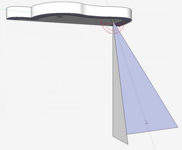
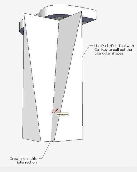
Step 8: Using the Push/Pull Tool (with the Ctrl Key tapped), pull out the triangular shapes. The intersection of these shapes will create the splayed leg centerline. Draw a line in this inter section.
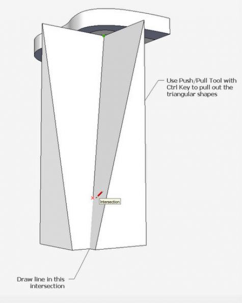
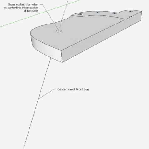
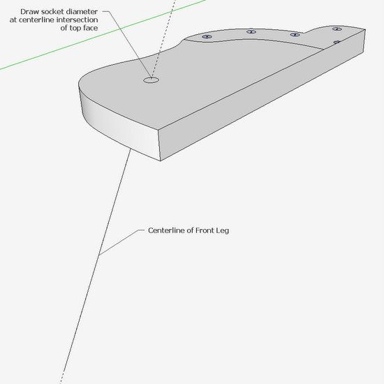
Step 9: Delete the waste triangular shapes leaving the leg centerline. With the Tape Measure, double click on the centerline. Using the Circle Tool, draw the leg socket location on the top face of the seat. Repeat these steps for the back leg.
In my next blog, I’ll show the making and positioning of the undercarriage components – legs and stretchers.




Log in or create an account to post a comment.
Sign up Log in