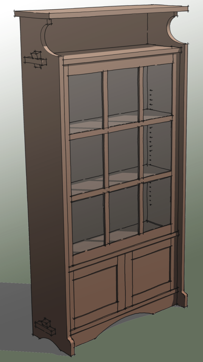
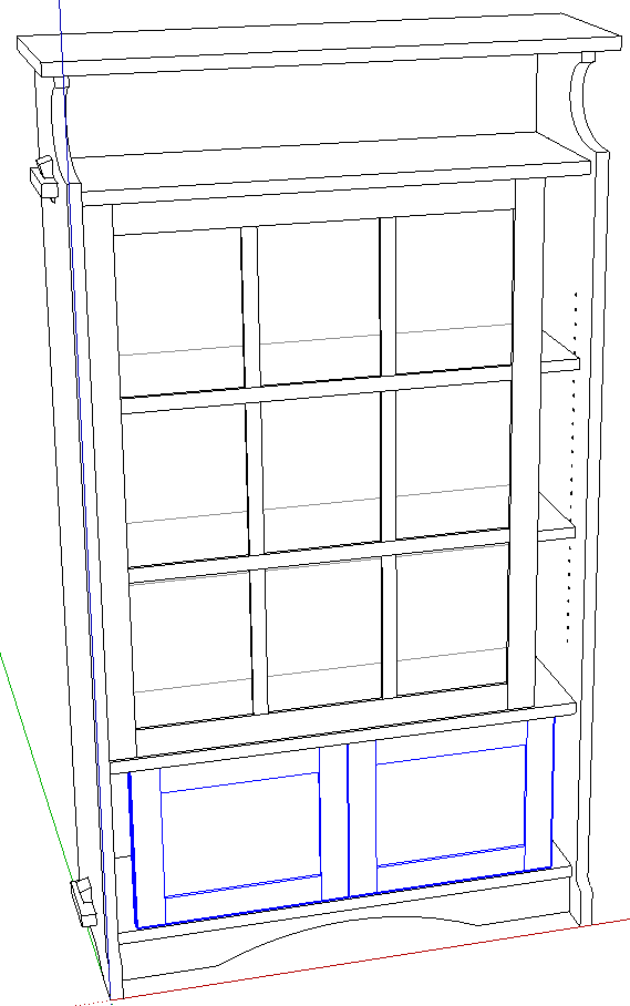
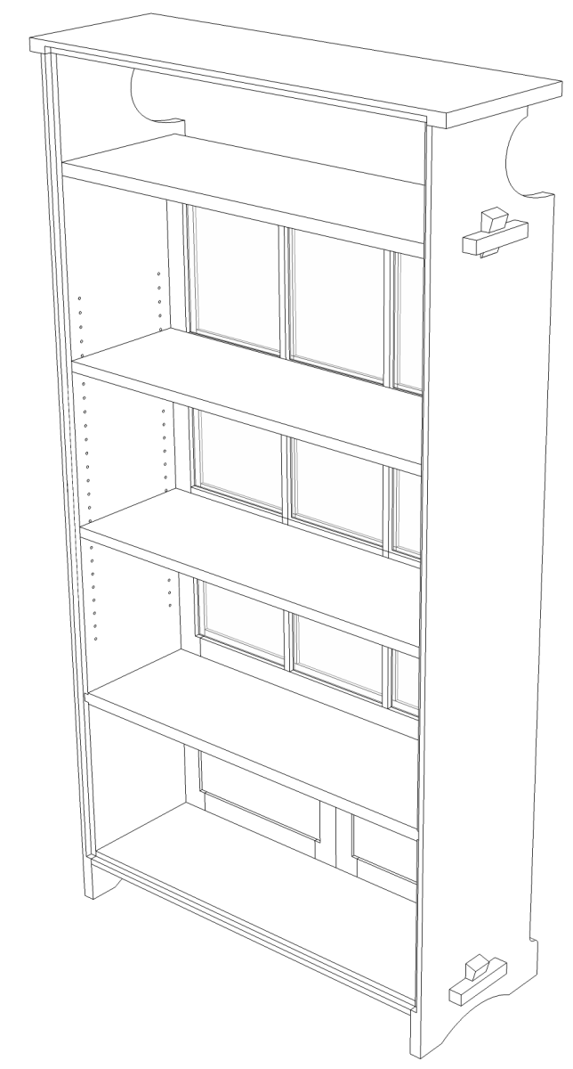
In my previous blog entry I mentioned that, after drawing the model to the dimensions of the original, I would like to make it slightly deeper. I also think wider would be good. At the request of one of our readers, here’s is the way I would go about resizing it. The process for me involves using just Push/Pull and Move. The trick is making sure you select only those things that need to move. If you miss an edge that you should select or include one you shouldn’t have, you will deform the geometry so you want to be careful. A little over a year ago I did a blog post with a video showing the same sort of thing where I converted a small fern stand into a hall bench.
Some folks would be inclined to use the Scale tool for this but it won’t work correctly because it’ll end up rescaling the details along with the overall model. There’s a great plugin called FredoScale that is extremely useful for some things. It could be used for this but I find it’s faster to use the native Move and Push/Pull tools.
This process of modifying is an important labor saving skill. If you make components that you will reuse in other models, you’ll use these same ideas to make those components fit. For example in my recent post about kitchen cabinets, I used the same process to make the different cabinet sizes. A few years ago I drew some furniture models for a manufacturer. Many of the models in a collection use the same basic parts with dimension changes. Instead of drawing each part, I simply resized the ones I already drew which saved me a great deal of time and work.
I’m starting by making the bookcase 1 in. deeper. Then I’ll make it 3 in. wider.
Normally I would do almost all of the resizing on the components in place but you may find that it is easier to copy components out away from the model to improve visibility. If you’ve made layer associations already, you can turn off layers to hide components that are in your way. You could just hide them temporarily or you could use X-ray for the entire process. For some parts I will use X-ray view but generally I find it difficult to see through the clutter. With practice you will kind of just know you’ve got things selected without seeing them.


For this demo I copied the side panel out so you can see the details that need adjustment. I temporarily removed the arch relief at the bottom because there’s not really a good way to resize it. You could use the scale tool but the original curve is circular and scaling its width would make it elliptical. For the time being I’ll keep the circular curve and so I’ll just redraw it.
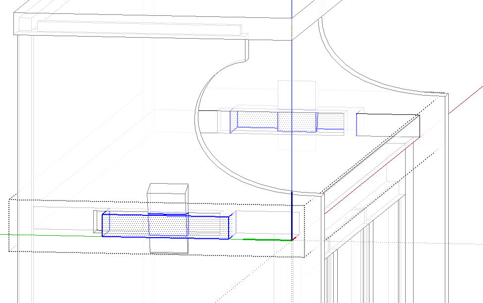
In the images above, I’ve set the Camera to Parallel Projection and set the view to Left so I’m looking straight at the inner face of the right side panel. Use a left to right selection box to select the rabbet for the back, the back end of the tenon on the top and the rear line of shelf pin holes. Then get the Move tool and move the selection to the left 1 in. Then I selected the mortises for the top and bottom shelves and moved them to the left 1/2 in. to keep it centered on the side. Redraw the arch detail at the bottom. After making the changes on the side panel, the copy, if you made one, is no longer needed and can be deleted. Make sure you get out of edit mode before deleting it.
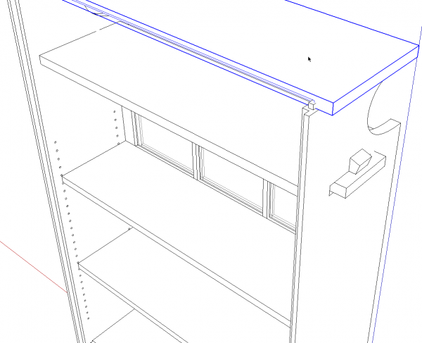
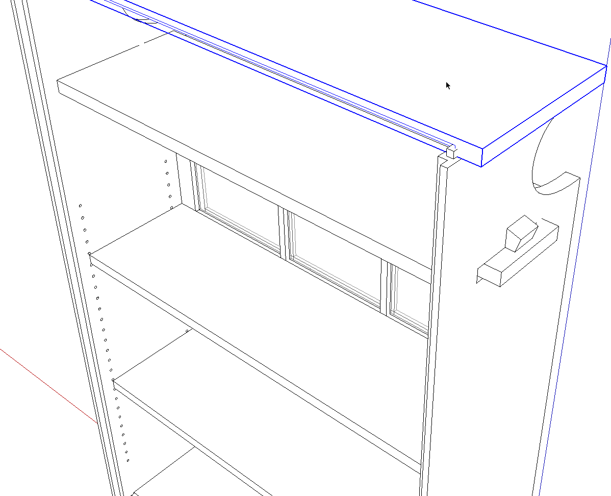
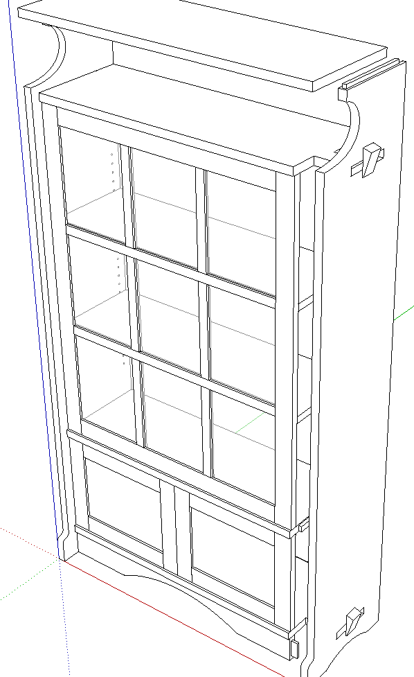
I’ve hidden the back and you can see the horizontal parts now need adjustment. Start at one end and work down through the model. An orderly approach to this will make it go quickly.
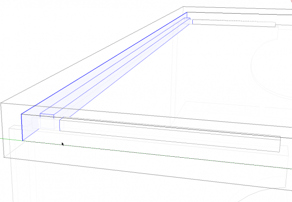
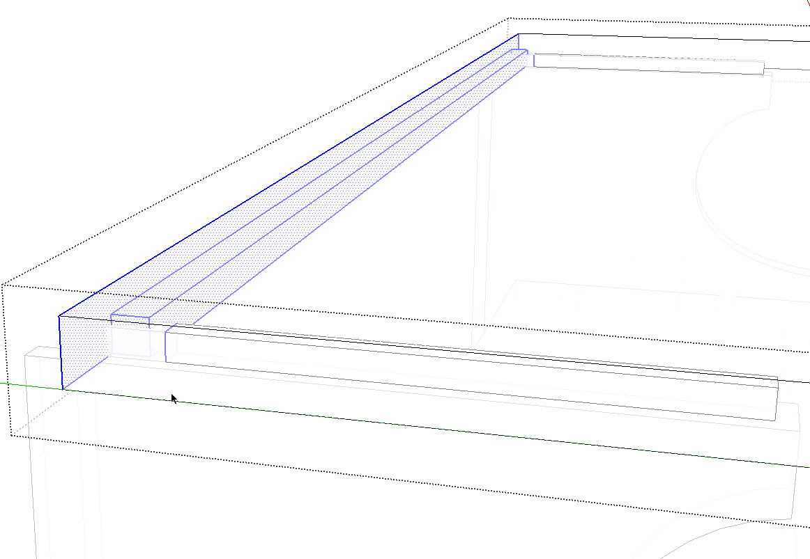
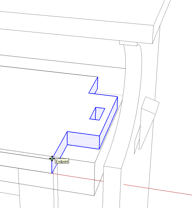
With the top component open for editing, Drag a left to right selection box to include all of the rabbet for the back and the back faces of the mortises. This is a good time to use Parallel Projection and a standard view. I’ve switched to X-ray view so you can see what I’ve got selected but if you drag the selection box to include only the rear half of the top, you’ll have everthing you need in the selection.
Move the selection back making sure you are moving on axis and move the correct distance.
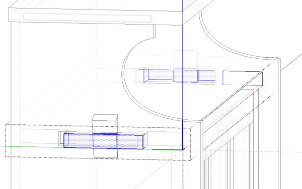
Moving down to the top shelf, the back edge can be moved back with Push/Pull or with Move. Push/Pull is a little faster. Then the tenons get moved back 1/2 in. to match the mortises. You can select both tenons at once by going to Parallel Projection and a standard view that shows you the side of the case.
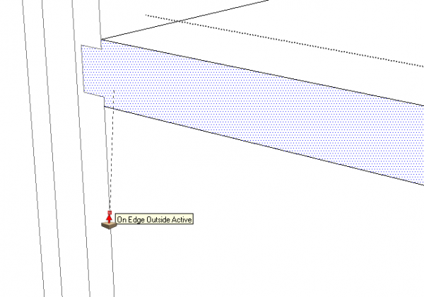
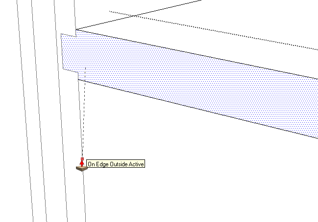
The movable shelves as well as the fixed shelf below the glass door can be adjusted with Push/Pull. In the image above you can see that I pulled the back face of the fixed shelf back to the edge of the side rabbet. There’s no need to enter the distance here. You can do the same sort of thing with the Move tool if you grab a corner that will correspond to a corner on the adjoining part. It’s probably a good idea to lock the move direction once you’ve started the move by holding the Shift key.
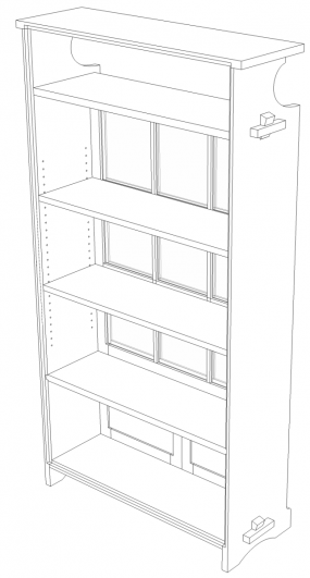
After moving the wedges in the tenons, we’re done with the depth. Although not shown, I did move the back panel, too.
Now I’ll change the width. The process is the same as for the depth.
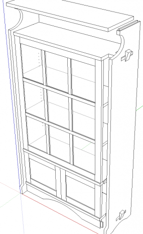
I’m working toward the right so I moved the right side and the wedges over 3 in.
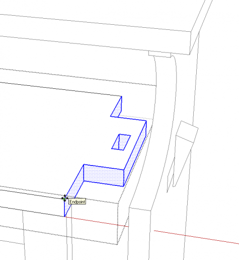
Left to right selection boxes around the ends and the Move tool make quick work of increasing the length of the horizontal pieces. The movable shelves can be adjusted with Push/Pull as before. Before adjusting the length of the apron, I filled in the arch and deleted the edges. Then I drew the wider arch after resizing.
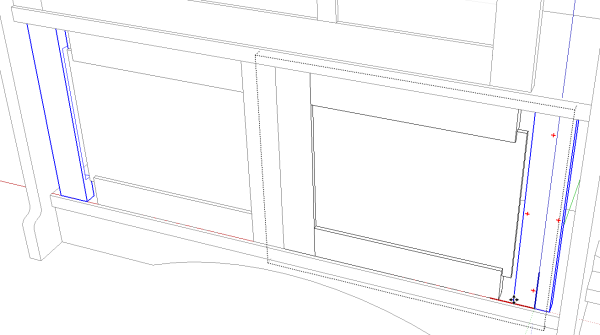
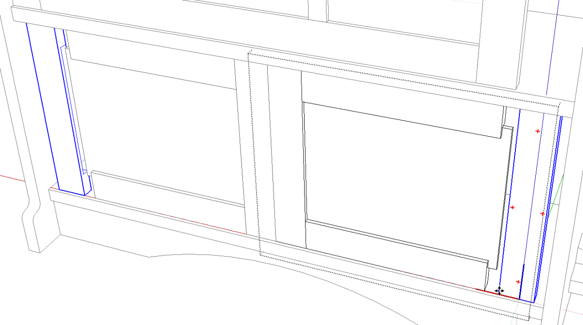
When I made the lower doors, I drew one and made it a nested component. Then I copied it to make the opposing door. This copy was flipped to make it a mirror image of the first. Although that flipping business doesn’t appear to have any impact, here’s one of the benefits of doing it. I moved the door components so they are centered in the opening. Then I open one of the door components for editing. You can see that I’ve selected and moved the outer stile on the right. the one on the left is moving, too.
If you choose to make nested groups of components for things like doors, you’ll have to edit each group individually.
Making adjustments to the rails and the panel will also be done correctly because of the flipping.
Aside: Another benefit to flipping one copy of the doors shows up if you cut hinge mortises and drill holes for pulls. You need only open on of the door components for editing, select one stile component and choose Make Unique to break its relationship with the other stile in the door component. Then go ahead and edit the stiles to add the details. Also, if you want to add a door pull component into the door, you only need to add it to one door component and it will appear in the other as well.
For the glass paneled door, I moved the right hand stile to the right 3 inches. The right hand vertical muntin and lights were moved 2 in. The left vertical muntin and center lights were moved 1 in. Then Push/Pull was used on the edge of one of the lights to enlarge the glass. I drew the halving joints in the muntins and the ones in the horizontal muntins had to be moved to correspond to the new positions of the vertical muntins.
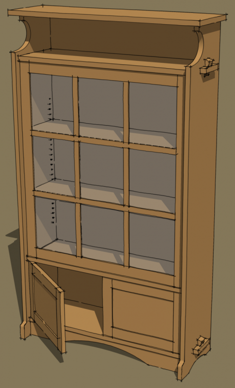
And that’s that. It probably takes longer to read this than it does to do it.





Log in or create an account to post a comment.
Sign up Log in