In my previous blog post I wrote about setting the insertion point for components to make them easy to place in models. A couple of readers let me know that they weren’t sure how to do this. Some time back I wrote about the axes in SketchUp and covered this a little but here’s a bit more detail.
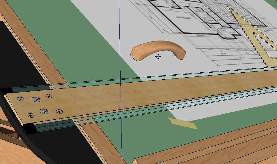
If you drag a component into a model from a component library, the cursor will show as the Move tool placed at the insertion point. You’ll have ahold of the component at that point.
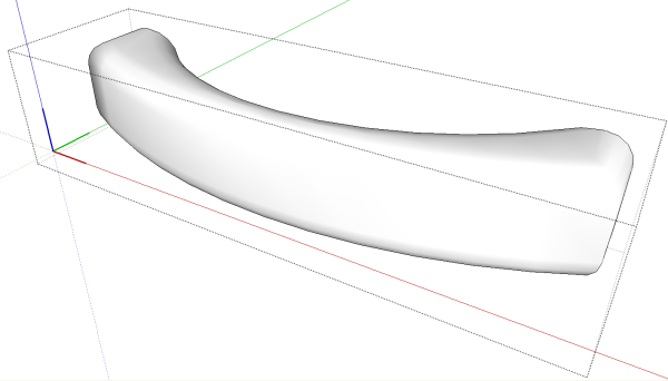
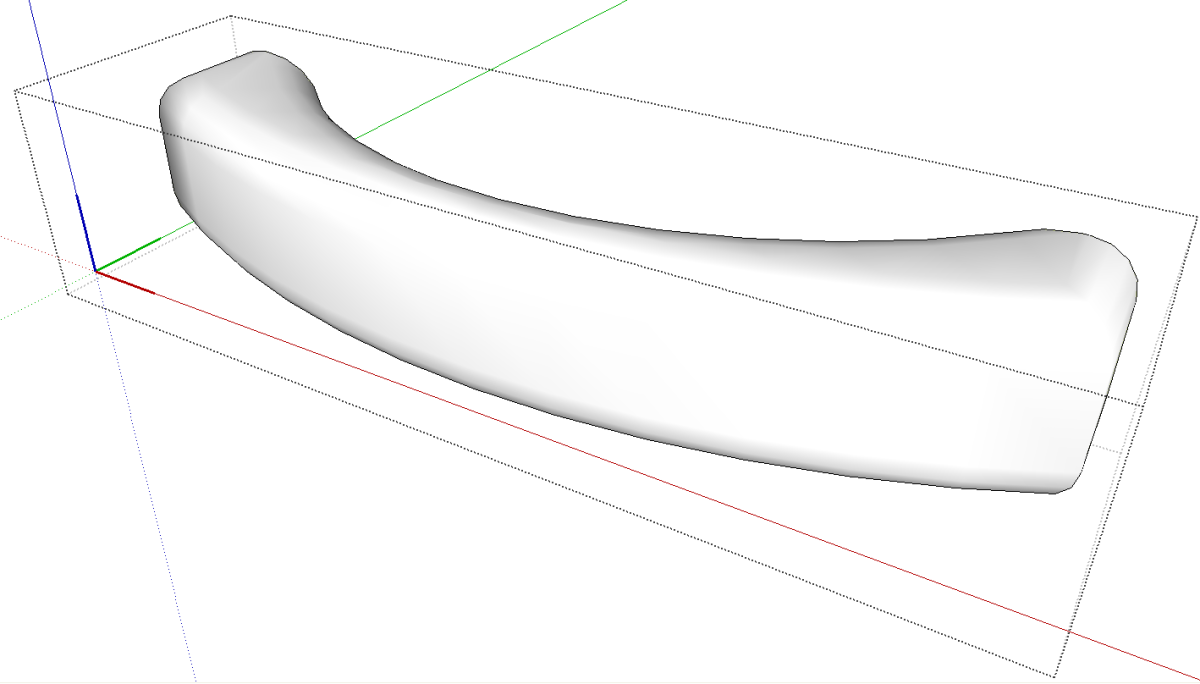
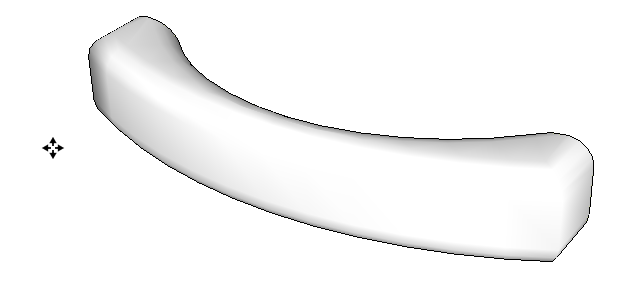
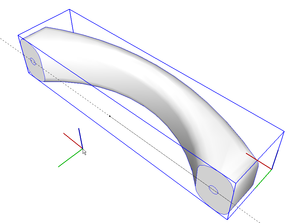
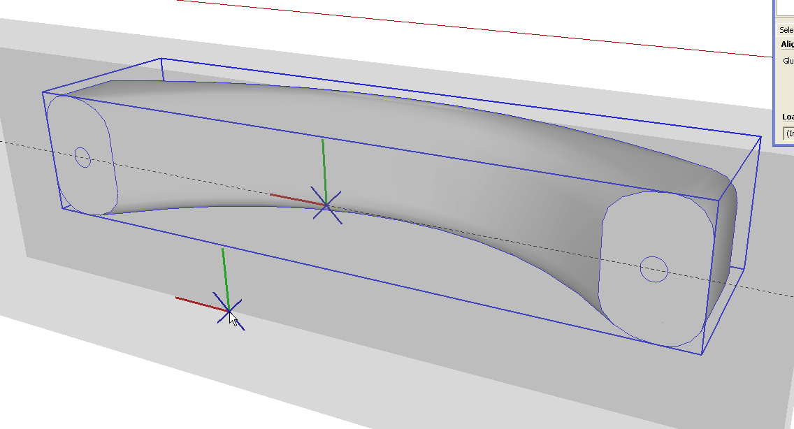
When you make a component, it is given its own axes. They are aligned with the global axes and are positioned such that the origin is in the front, lower left corner of the component’s bounding box. Front, lower left is defined based on the standard views. If you draw your component so its front isn’t parallel with the red axis this could be confusing. As you can see, in the drawer pull example, this puts the origin outside and in front of the component’s geometry.
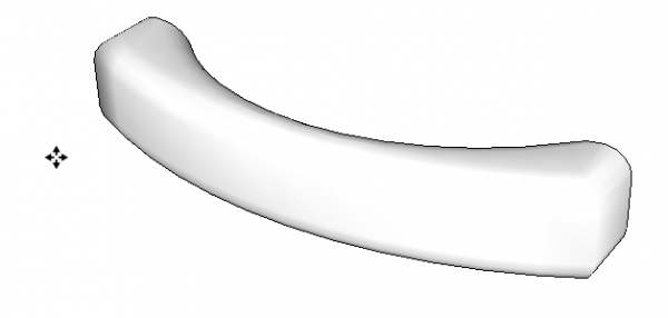
This origin is the insertion point which is marked by the Move tool, above.
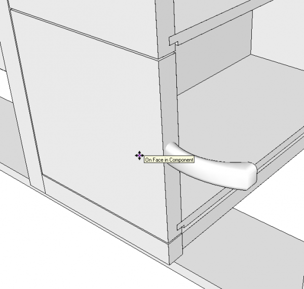
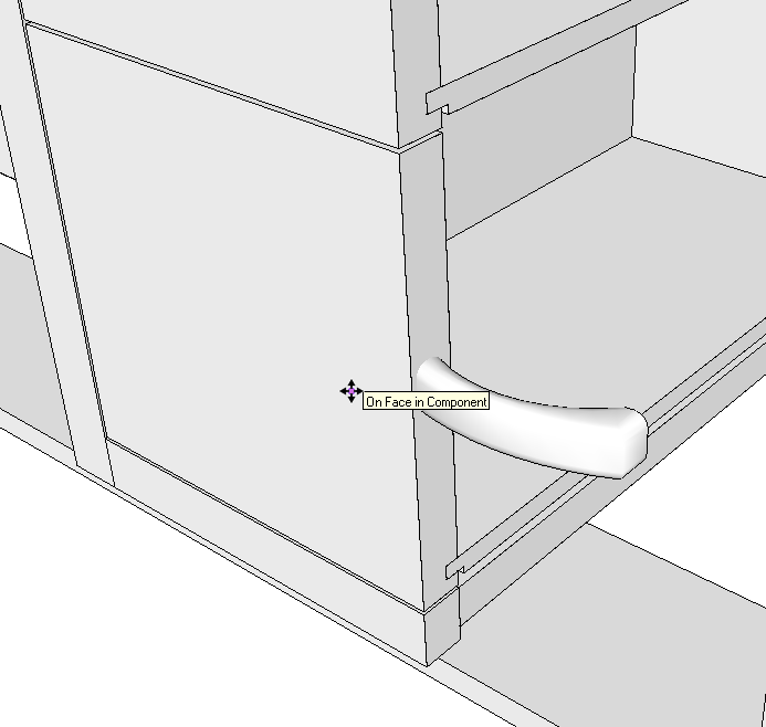
So when we try to bring in this component to use in a model, placing the component is somewhat problematic. When I attempt to place the pull on the drawer front, you can that with the cursor on the surface, the pull is located inside the drawer front. I could drop the component momentarily and regrab it with the Move tool to place it correctly but that would be tedious at best.
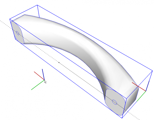
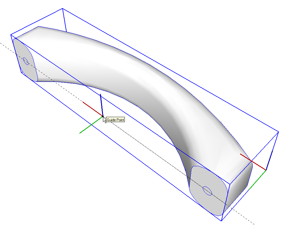
To make it easier to place the component, we can take a few seconds to relocate the component’s axes and origin. I start by locating the desired origin with guidelines/point. In this case, it makes sense to me to locate the insertion point at the center of the component’s back plane so I’ve put in a guideline for the centerline of the pull and measured half way down the centerline to identify the midpoint. You could also use a pair of intersecting guidelines if you wish. Then, with the component selected but not open for editing, right click and choose Change Axes from the Context menu. The cursor shows the axes to be set.
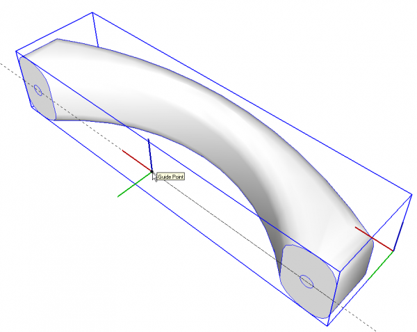
Click on the point first to set the origin. Then click along the guideline for the red axis and then set the green axis. It should snap to easily to be parallel to the global green axis but if you have trouble, try orbiting the camera to change your viewpoint or use crossing guidelines set out on the red/green plane. When you set the green axis make sure the blue points up for the component.
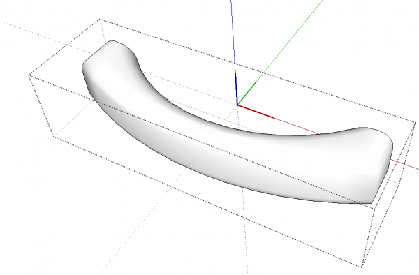
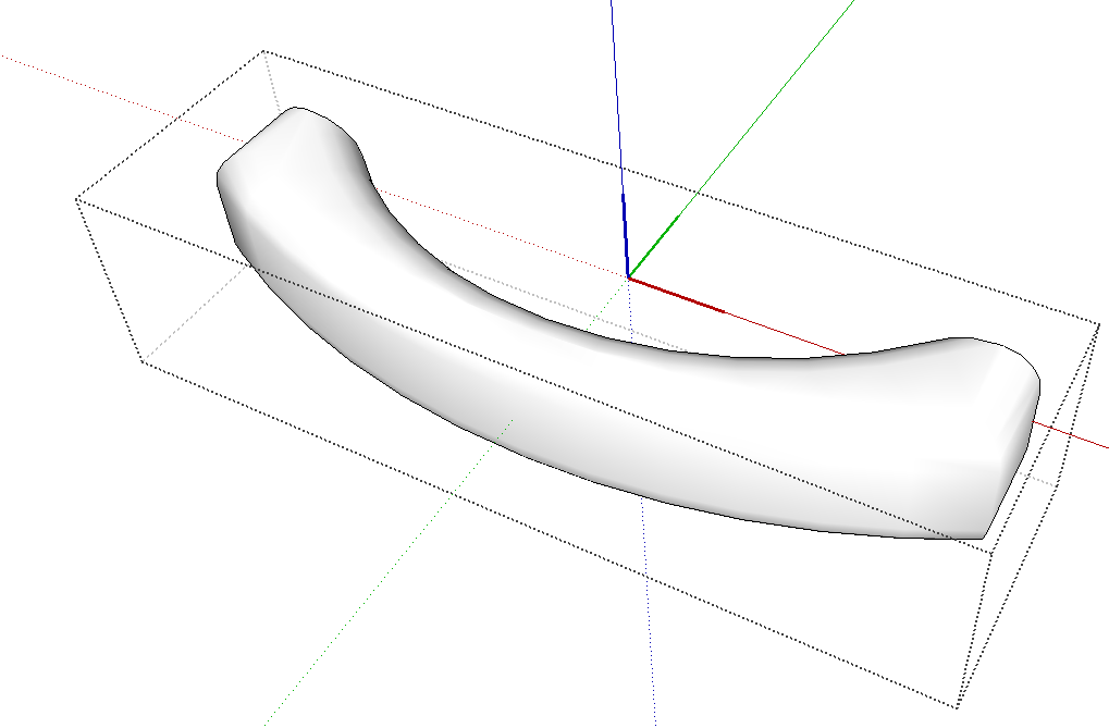
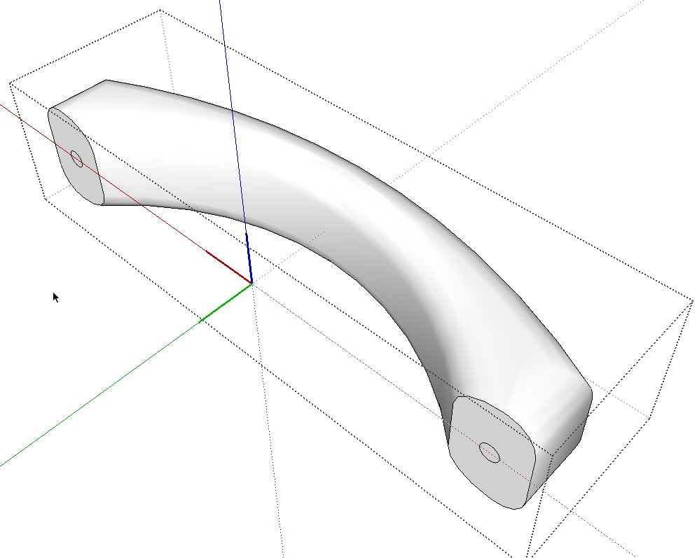
With the component open for editing, it looks like this.
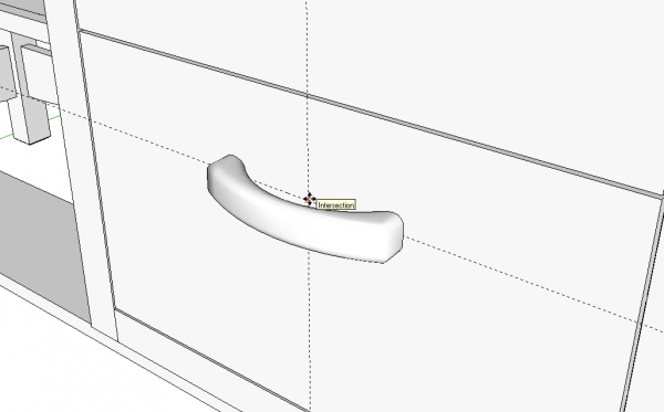
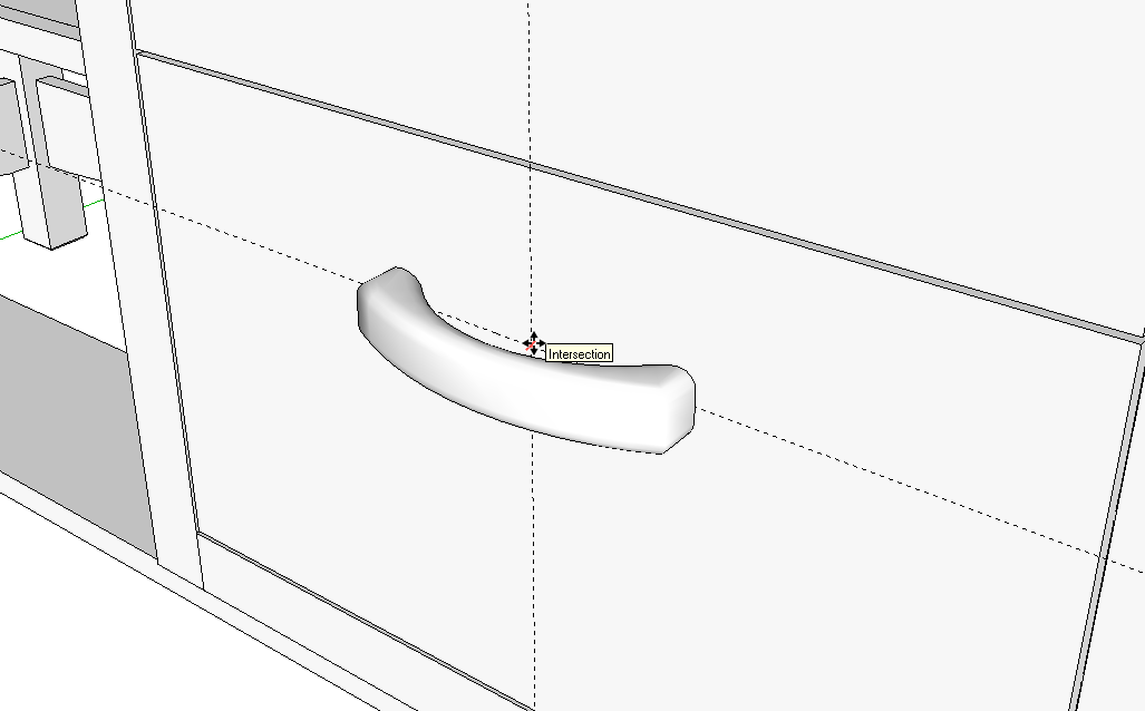
And now, when the component is brought into a model, it can be dropped exactly where you want it. In this case I identfied the location with crossing guidelines.
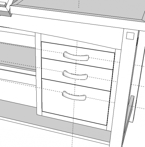
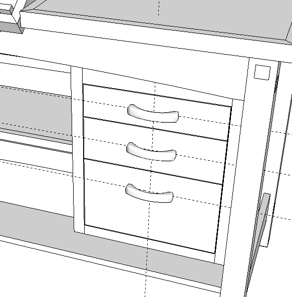
And putting the pulls in on all the drawer fronts only takes a couple of seconds.
As it stands at this point, the pull can be placed precisely on any front surface which, for most of my projects is all I need. If you want to have the option to as easily place the pull on a face with any orientation, you can use the “Gluing” feature.
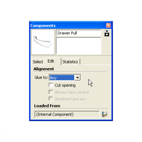
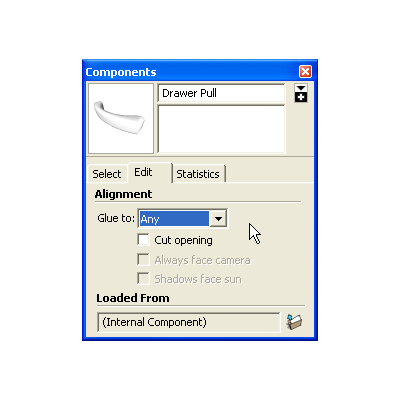
You can choose the gluing characteristic when you create the component of select the component in the In Model library and then click on the Edit tab I did above. You can specifiy only vertical faces or horizontal ones. In this case I’ve chosen “Any”.
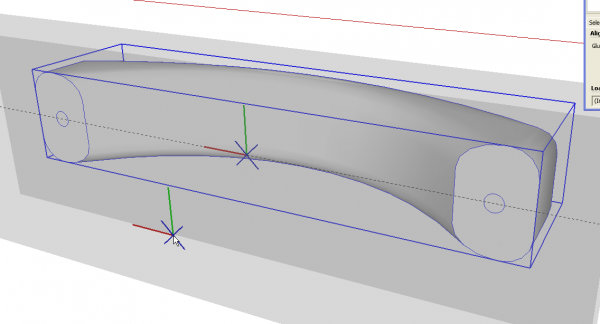
After making that setting, right click on the component and choose Change Axes. Notice the different appearance of the axes when gluing is chosen. There’s a grey transparent plane represnting the gluing plane. The gluing plane is on the component’s red/green plane so the green axis points up in this case. Notice now there’s no indicated blue axis for the component.
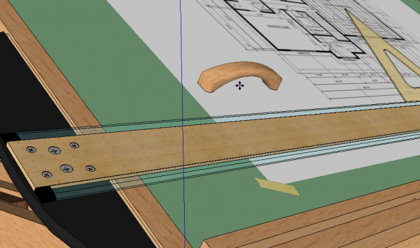
With the componet set to glue to any face, it is now a trivial matter to place the pull on even an angled surface.
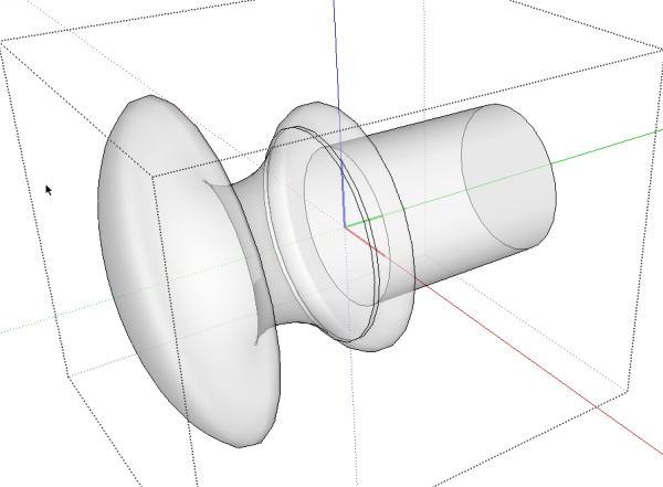
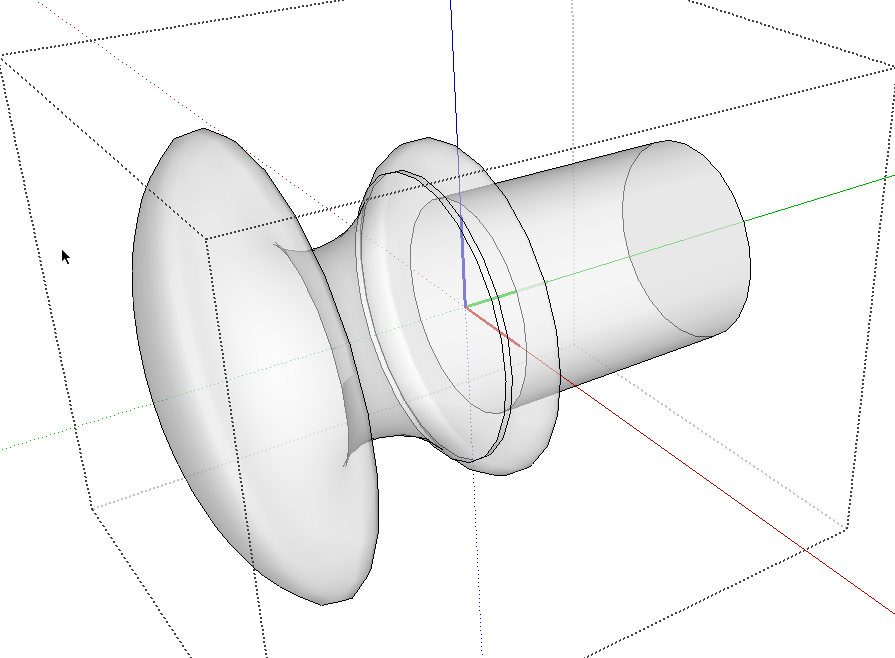
With some components such as this Shaker-style drawer knob, you’ll need to put the component’s origin inside the component. To do something like that you may find it easiest to set the crossing guidelines as needed and then shift to Wireframe face style so you can work inside the components face and see what you’re doing.
After a little practice with this you’ll find that it takes only a few seconds to change the axes and possibly save yourself those seconds many times over when using the component in future models.



Comments
Thank you David for this useful and highly time-saving technique. As a recent user of SketchUp, I have been struggling with many component placement issues as one of the first projects I had to tackle was a complete staircase.
Hi SnoogthePoog. I'm glad this has been helpful. A detailed staircase drawing could include a large number of the same components so setting the insertion points logically is useful. Another thing you would probably find useful for drawing staircases is the linear array capability of the Move tool.
Dave
Thanks Dave...great tip and a good article!
Hi Dave,
I found the quickest way of locating the middle / center point of a square, rectangle, cube or block is to draw a diagonal line and pick its mid point.
For cylinders, draw a line from the 3 o'clock quadrant at one end, to the 9 o'clock quadrant at the other end, then pick its mid point.
Cheers
p.s. I would like to know your soft shadow method.
Hi David,
Nice work.
To quickly find the middle / center of a rectangle, square, cube or block, I draw a diagonal line and then find its mid point.
For cylinders, I draw a line from a quadrant - say 3 o'clock at one end, to the opposite quadrant - 9 o'clock, at the other end.
Cheers
Yes, that's one way to find the center but in most cases you can use SketchUp's inferencing. In cases where that doesn't work, guide lines can be used without modifying the existing geometry.
Brilliant great way of component insertion.
Log in or create an account to post a comment.
Sign up Log in