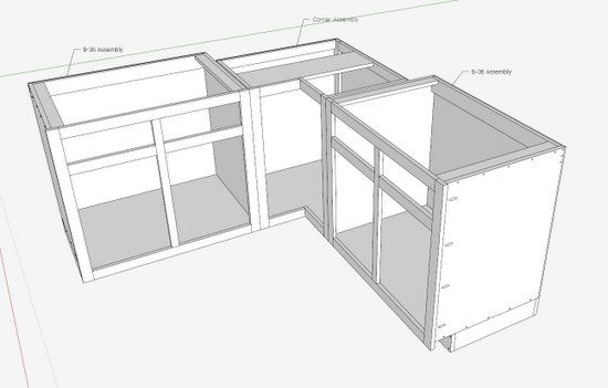
A few weeks ago on this blog, I presented my Kitchen Cabinet for an engineer. I did not include the paneled door, so this entry will fill that void. I chose to use a Shaker style cabinet door with a flat panel, and the door is inset to the face frame. Creating other styles and positioning would use the same procedure that I will show in the following steps.
I think the doors for most kitchen cabinets are made with equal widths for the stiles and rails. I’m not happy with the way that looks, so I’m making the lower rail 1/2-in. wider than the stiles or the upper rail.
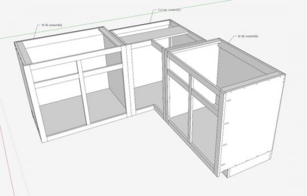
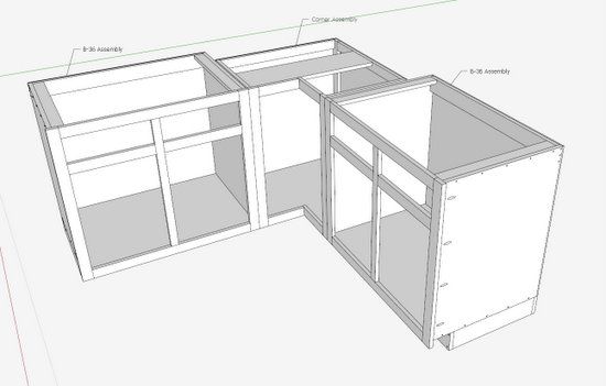
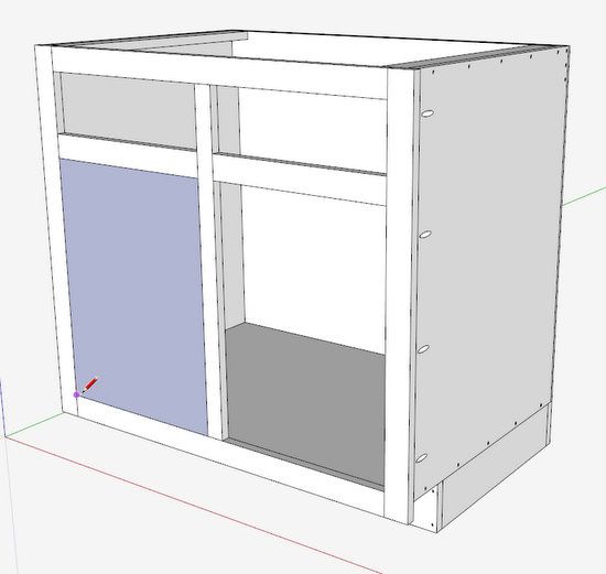
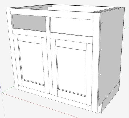
Here are the 36-in. wide base cabinets without the doors and drawers.
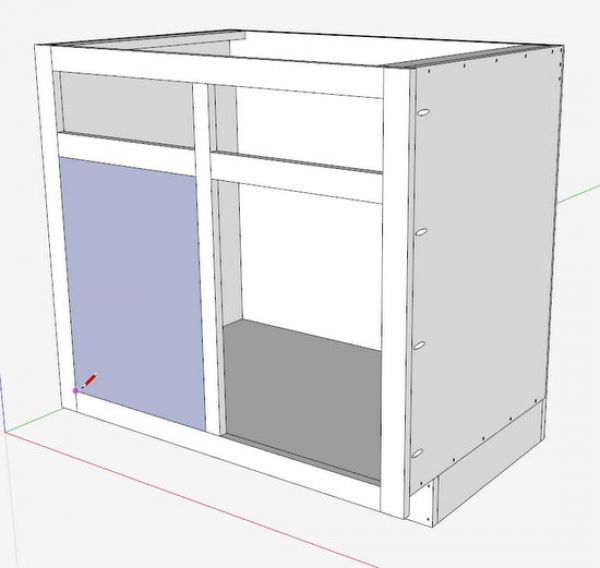
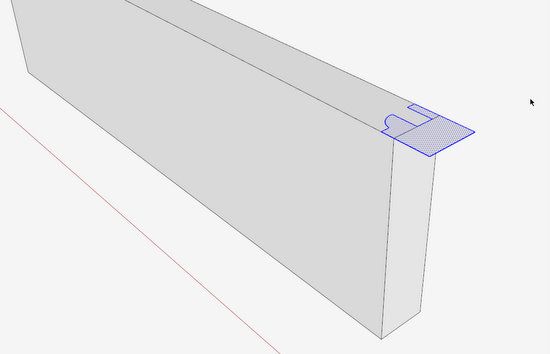
Step 1: Draw a rectangle around the open perimeter of the cabinet – shown in blue color below. Double click on this face and make it a group.
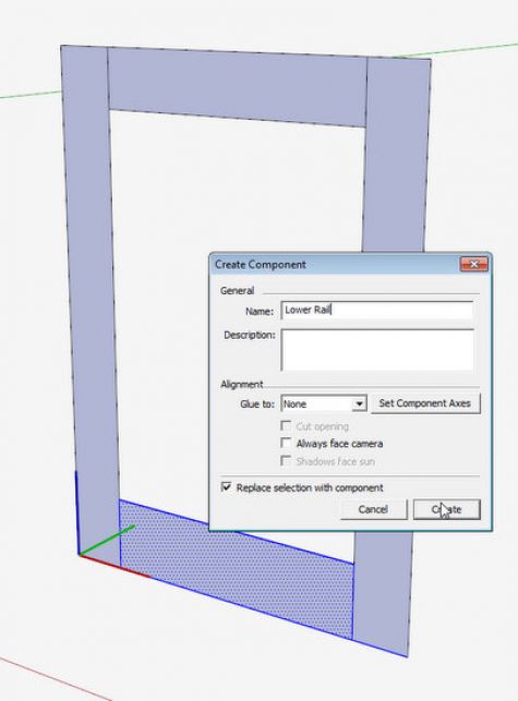
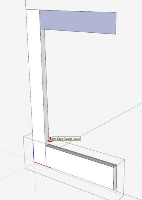
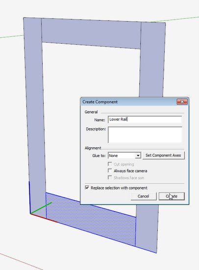
Step 2 & 3: Make a copy of the group and move away from the assembly. Draw guidelines for the sizes of the stiles and rails. Select out the two rails and the stile and make them components. Be sure to check the box Replace selection with component.
Step 4: With Push/Pull Tool give the rails and stiles a thickness of 3/4-in.
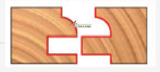
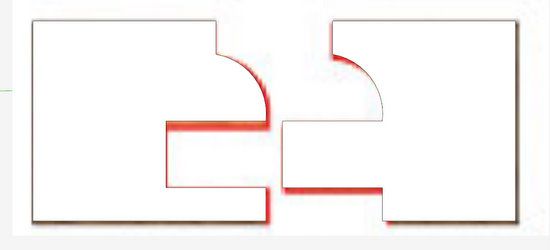
Step 5: Find a router manufacturer’s drawing on the Internet for a matching pair of cope and stick bits. Import a JPG picture into SketchUp to create the router bit shape in SketchUp. Alternatively, you can use the dimensions provided in the manufacturer’s data. Create cutter shaped faces as shown below and make them groups.
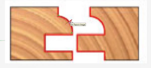
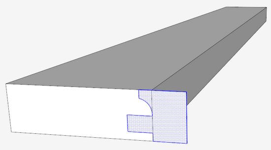
Step 6: Place a cutter shape on the end of the Stile and explode the group and the Stile.
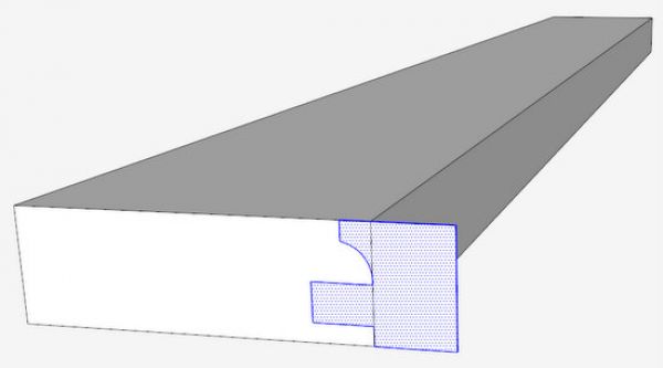
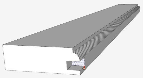
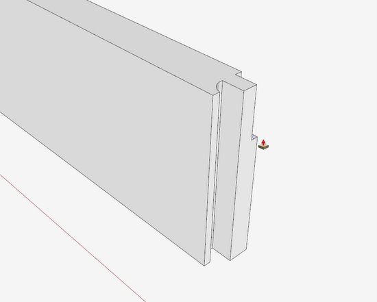
Step 7: Use the Push/Pull Tool to push out the shape along the inside edge of the Stile. You may need to select all and do a Soften/Smooth Edges to remove the extra edges in the bead. This completes the work on the Stile.
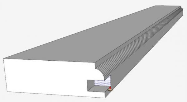
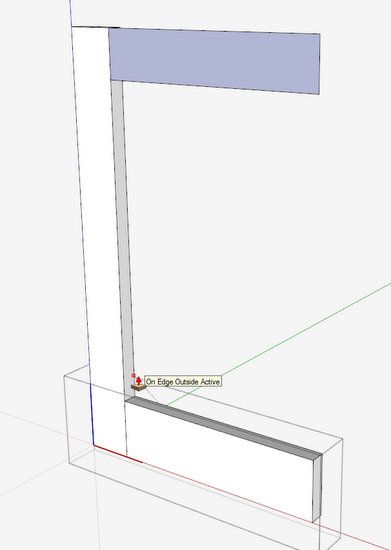
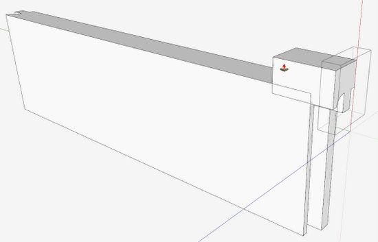
Step 8: Use the other cutter shape to route out the cope on the end of the Lower Rail. Before you do that, use the Push/Pull Tool to lengthen each end of the Rail by 3/8-in. Otherwise, positioning the cutter as shown below will take away 3/8-in. of the required length.
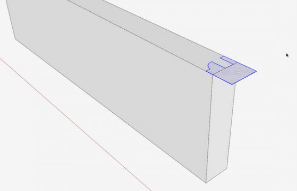
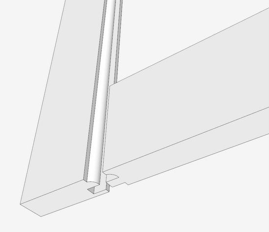
Step 9: Explode both the rail component and the cutter shape. Then use the Push/Pull Tool to route out the cope.
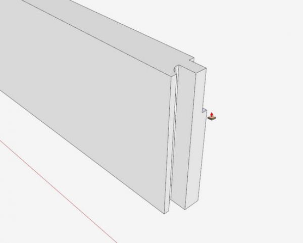
Step 10: Copy the coped end and move to the other end of the rail, and do a Flip Along the red axis. Then connect that copied shape to the corner of the other end. You’ll need to delete waste with the Eraser Tool.
Step 11: Now we need to create the shaped inside edge of the Lower Rail. This cannot be done simply with the Push/Pull Tool since we already have shaped ends.
Position the cutter at one end of the rail and use the Push/Pull Tool to create a cutter for the whole length. Make sure to extend the new shape beyond both ends.
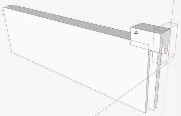
Step 12: Now the hardest part, however I’m going to do this using a shortcut available in the Pro version of SketchUp – Solid Tools. The Intersect function in the free version will accomplish the same thing, but would require more work.
I picked the Split Tool, one of several within the family of Solid Tools. I clicked the tool on each of the two groups.
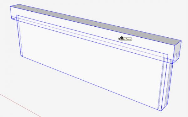
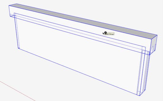
Step 13: After clicking the Split Tool on each of the above groups, I then used the Move Tool to pull apart the resulting three groups, two of which are waste.
Using Intersect is more tedious and time consuming. First it would be best to Scale up the parts by a factor of 100 before doing an Intersect. Otherwise, you will get some small gaps in the resulting rail. Also, with Intersect, there is considerable work with the Eraser Tool to knock out all the residual waste.
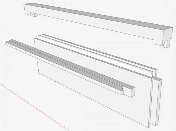
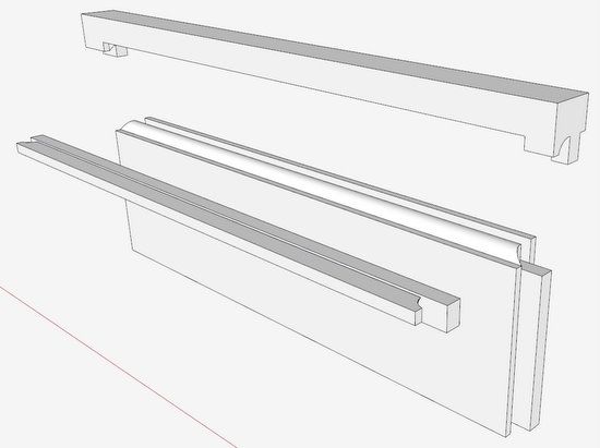
Step 14: Now we can begin to reconnect the two components – the Stile and the Lower Rail.
Step 15: Making the Upper Rail is easier, by using the Lower Rail as a starting point. I copied the Lower Rail to the upper position and flipped it around the blue axis. Then with Push/Pull Tool, trim the width of the rail by 1/2-in.
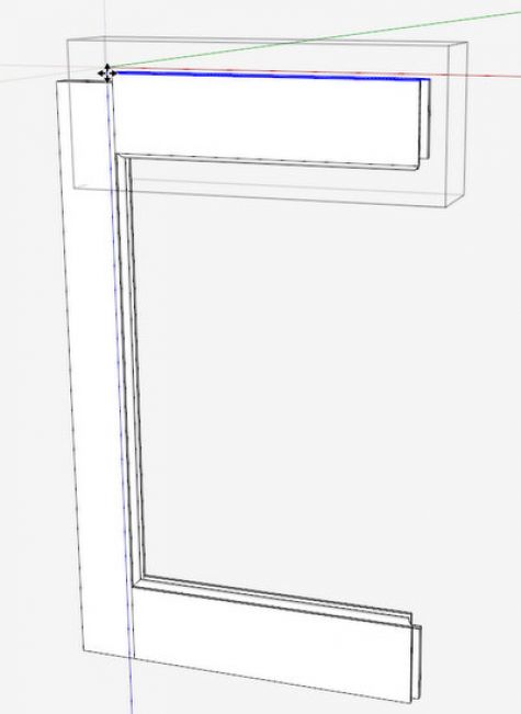
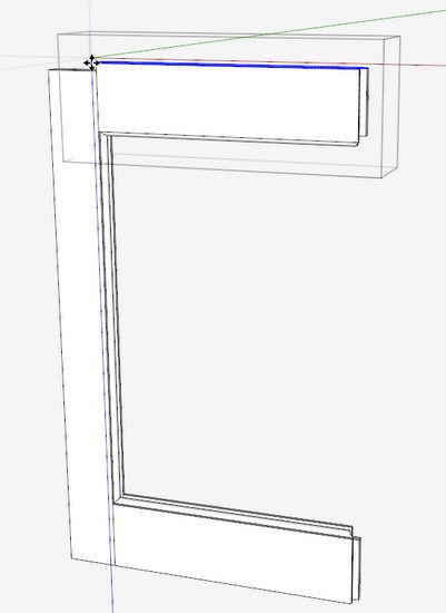
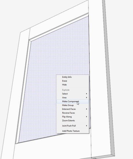
Step 16: We can use the assembled parts to make the door panel. Use the Line Tool to draw around the open boundary of the panel. Do this at the location of the groove in which the panel will insert. At this point the rectangle created is short of protruding into the groove. Double click on the face and make it a component called Door Panel.
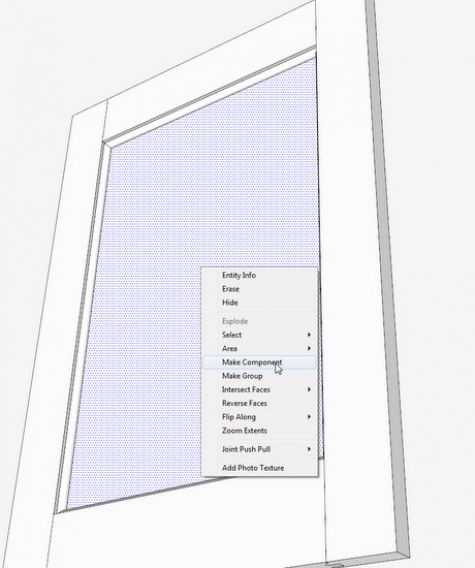
Step 17: Move a copy of the component off to the side and using the Push/Pull Tool give it a thickness of 1/2-in. Then pull out each edge of the panel by a distance of 1/4-in. This will create a panel that inserts 1/4-in. deep into the grooves. A panel of 1/4-in. thick is too thin. I would go at least 1/2-in. thick which will require a rabbeted edge all around the back of the panel. This can be created quickly with the Offset Tool and Push/Pull. Make sure to leave a 1/8-in. gap all around the back for expansion/contraction.
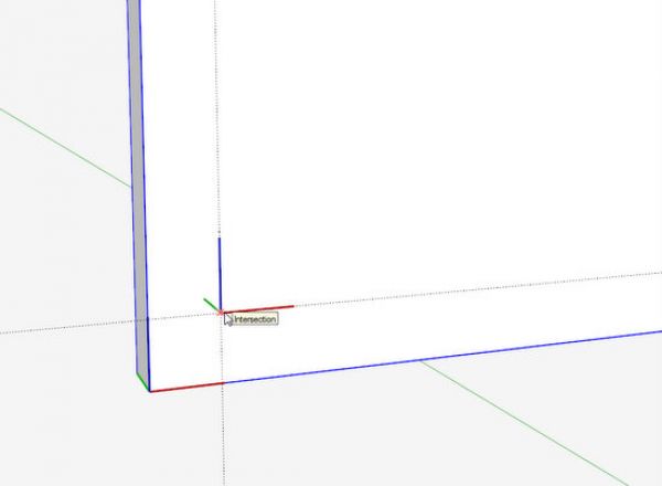
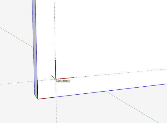
To help position the panel exactly into the frame, I shift the component axes at a point that will ensure a 1/4-in. insertion around the border. In this way, I can pick the panel from the Component Dialog Box and click it at the matching corner in the frame opening.
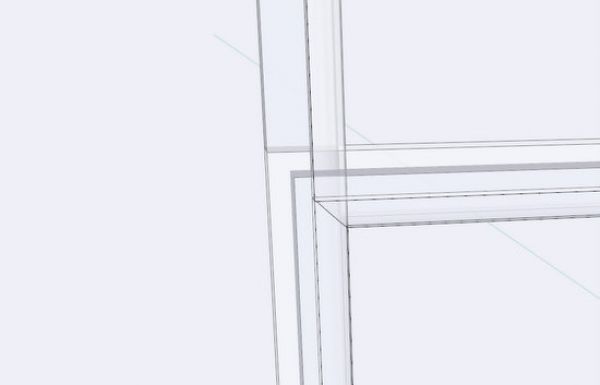
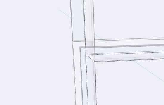
Step 18: You can check the positioning of the panel by turning on X-ray.
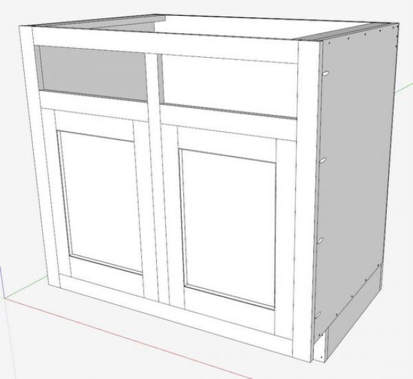
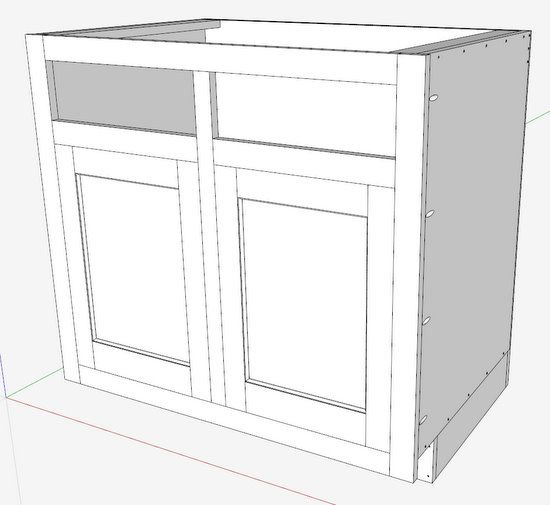
Step 19: The doors are installed in the cabinet. I’ll install hinges later.




Log in or create an account to post a comment.
Sign up Log in