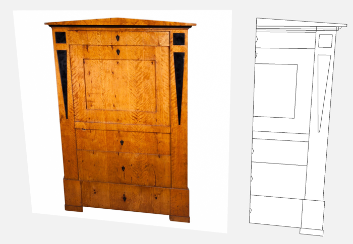
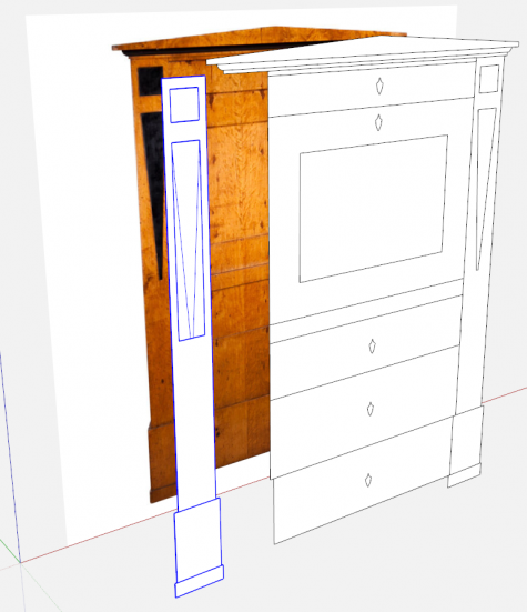
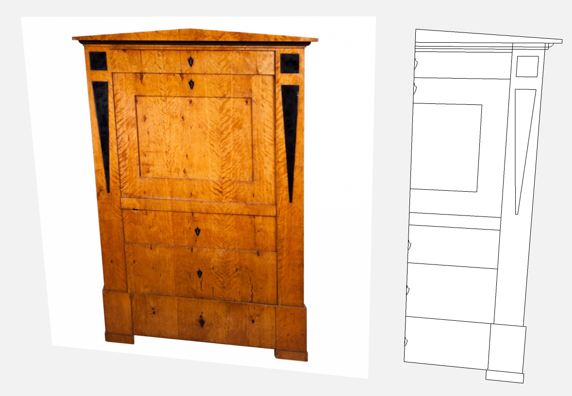
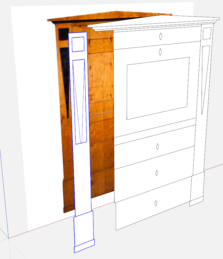
One of our regular readers sent me a SketchUp file he had been working on. It looked like this when I got it. His question related to painting his model to match the photo.
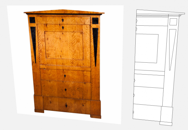
He had imported the image of the original cupboard with Use as Image selected in the import box. He hadalso drawn half of the model by tracing the edges. With any symmetrical piece, drawing only half of it makes a lot of sense. He drew each section and made it a separate component.
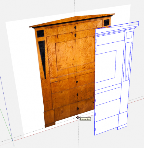
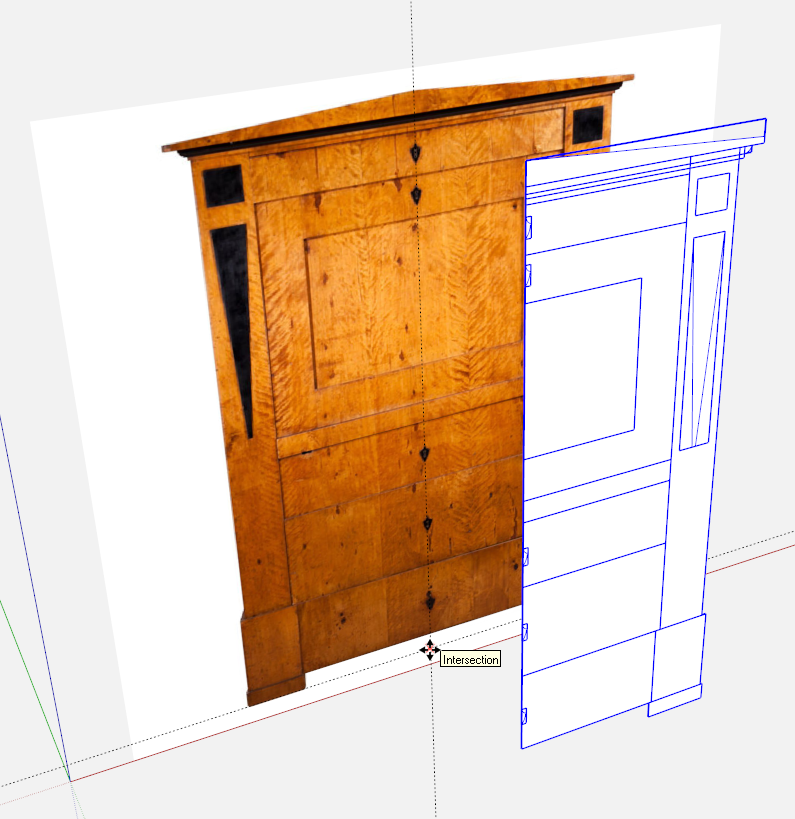
I had to do a few things before painting the model. First, I set a couple of guidelines. One parallel to the red axis and at the bottom of the image of the cupboard. The other parallel to the blue axis at the centerline of the image. These guidelines gave me a reference for moving the components so they would align directly in front of the image. Then I moved the model over in front.
If the model had still been in place where he’d drawn it, I would have simply moved it forward away from the image.
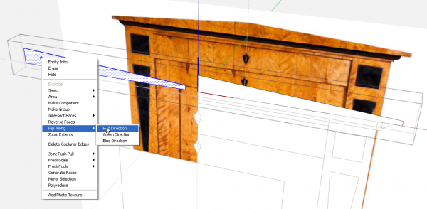
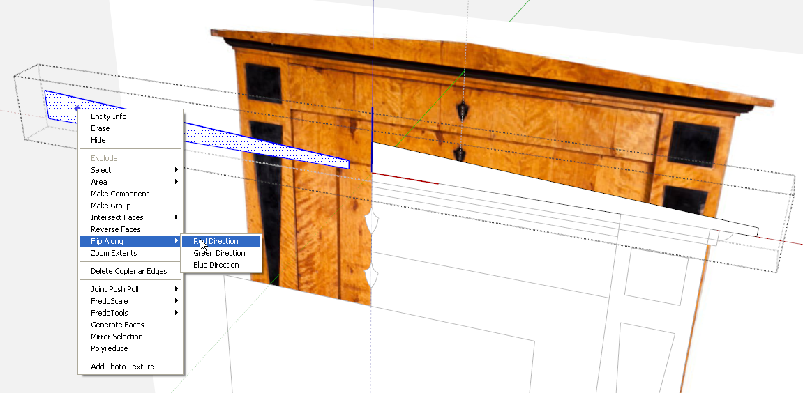
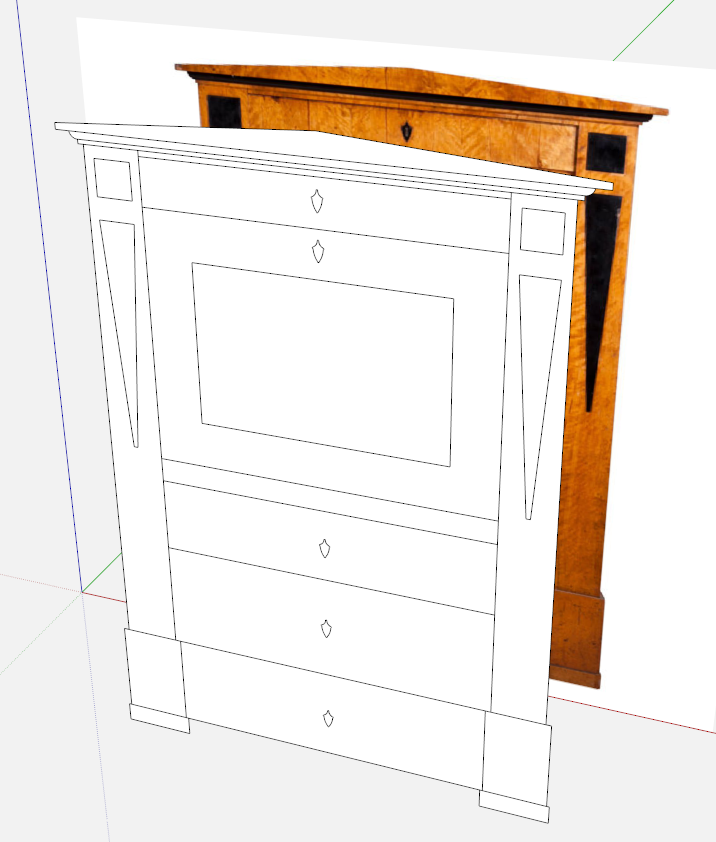
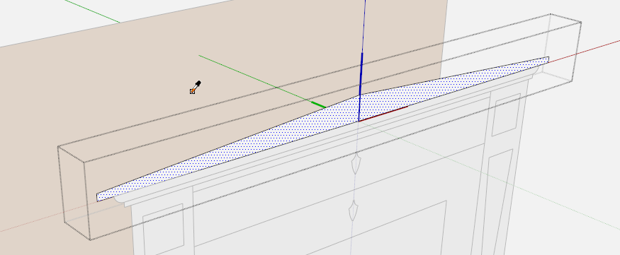
For the next step I set about creating the left half of each part. I opened each component for editing by triple clicking with the Select tool. This opens the component for editing and selects all the geometry in one step. Then I used Move/Copy to copy the geometry over toward the left. In the image, above, you can see I copied the pediment over far enough to the left so that copy is not touching the original. Then I right clicked on the copy and chose Flip Along>Red Direction. After flipping the geometry, I moved it back over to contact the original face and deleted the center line. Note that when you move the copy back over to the original, you want to make sure you grab the copy by the centerline or the corner at the centerline so that you can snap it accurately to the original.
I repeated this procedure for the rest of the components down the middle of the case. The escutcheons for the locks and the molding immediately under the pediment needed to be flipped as above. The rest of the components are simple rectangles so I just copied the faces over and deleted the centerline. You could measure the length of the half and move the left edge over by that amount but copying the face eliminates the need to do an measuring.
I copied the right side components over to the left and flipped them along the red direction. then I made the wood parts unique. I might not have needed to flip them since the aren’t going to be instances of the right hand components but I didn’t check to see if the components were actually center on each other. By flipping them, I didn’t need to be concerned with that and they are then symmetrical with the right side.
You can’t see it in the images but I moved the escutheons, the black squares and triangles out away from the other faces a tiny bit. This was done to prevent what is known as “Z-fighting”. This happens when two surfaces share the same space and the graphics card is trying to figure out which one to display. It tends to look like a sort of sparkling as you orbit.
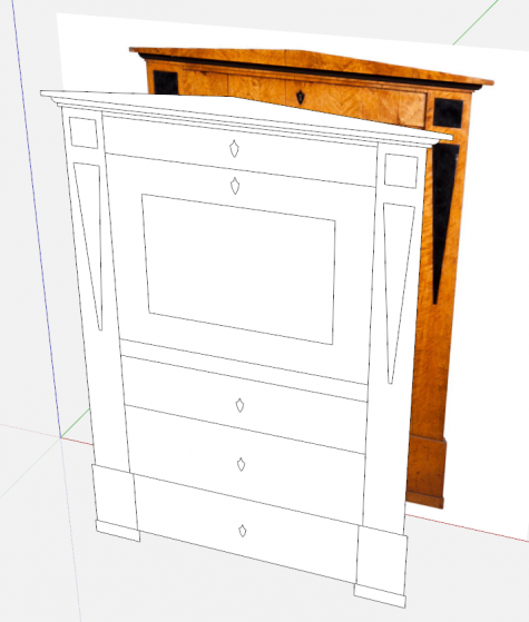
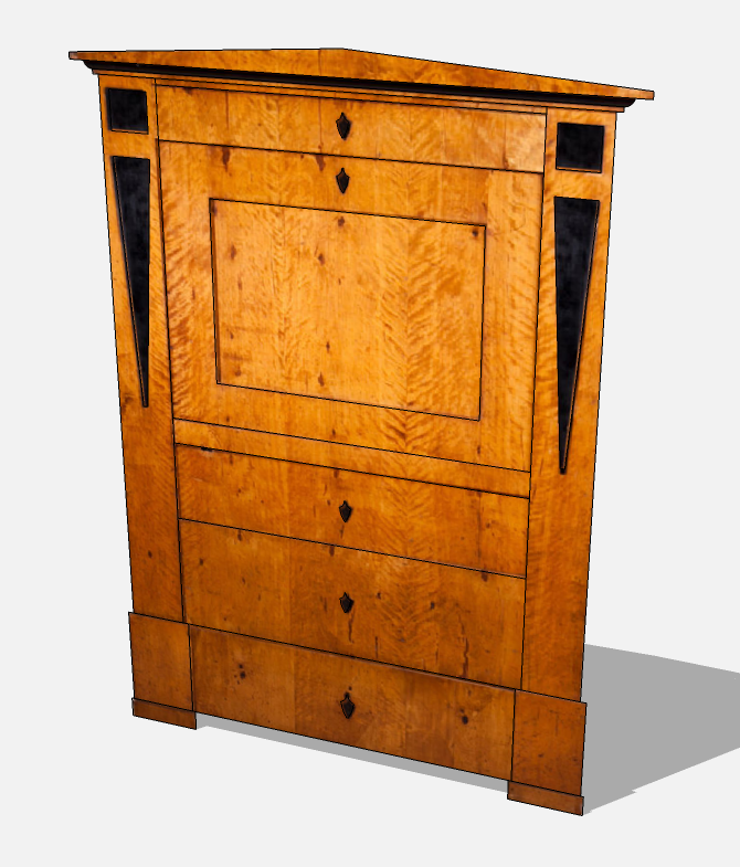
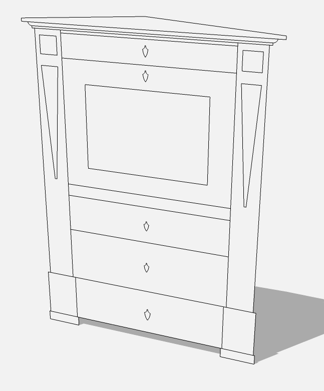
So now the cabinet drawing is completed.
By the way, if the parts had been drawn as 3D components, the process would still be the same. I was only give the front view of the cupboard and the 2D model. This whole process could be done to the sides of the cupboard too if the views existed.
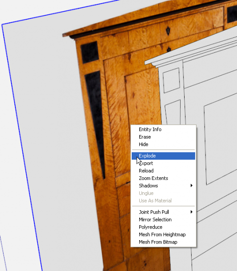
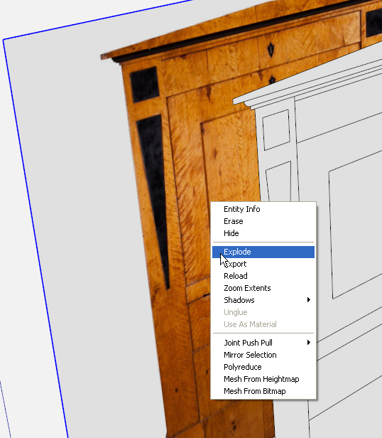
Next, I right clicked on the image and chose ‘Explode.’ This converts the image into a material.
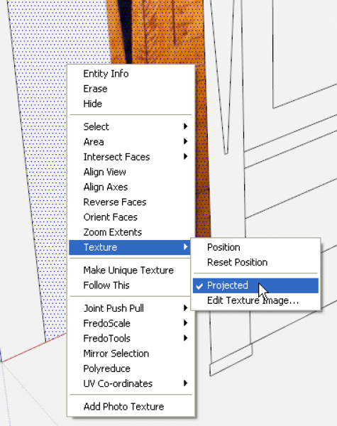
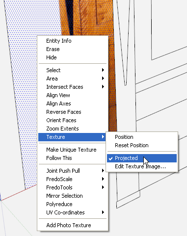
Next, right click on the face again and choose Texture>Projected.
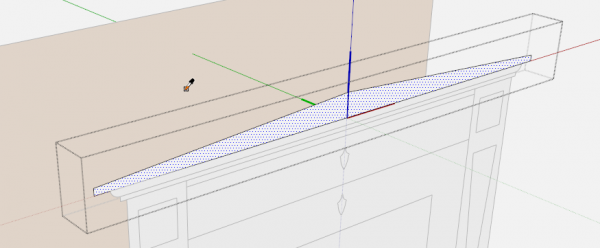
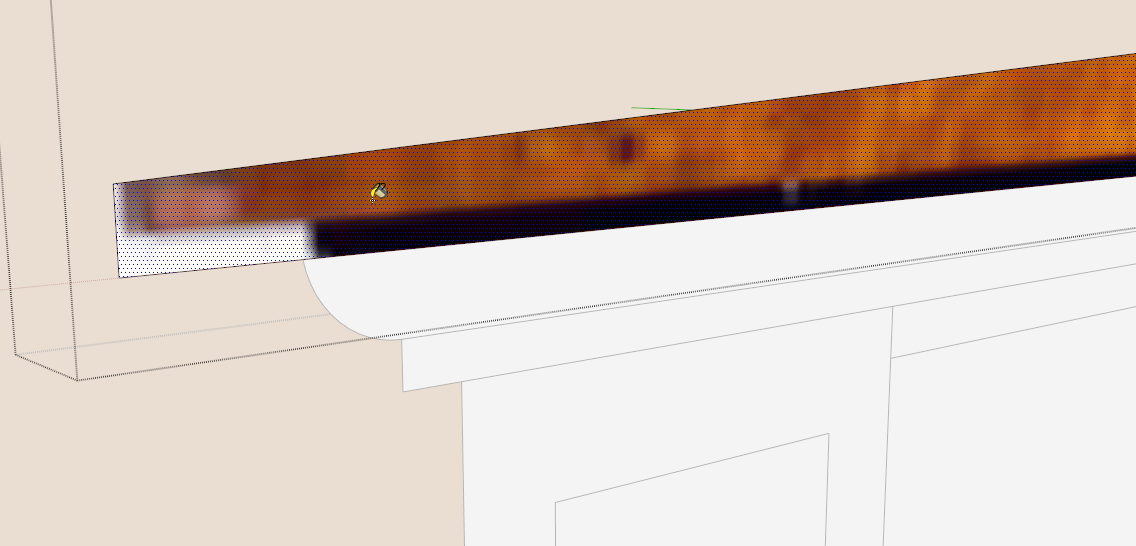
Now open the components for editing one at a time. Get the Paint Bucket tool and hold Alt on the PC or Command on Mac to sample the image of the cabinet. The icon switches from the paint bucket to an eye dropper while you’re sampling. Notice the image changes to a flat tan color when the component is opened for editing. That’s alright. With the component aligned with the model and the material set to ‘Projected,’ it doesn’t matter where you sample the image from anyway.
Release Alt or Command and click on the face in the component.
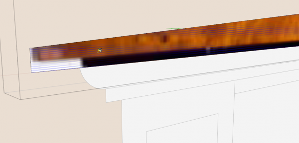
Here the material wasn’t aligned exactly right but we can fix that.
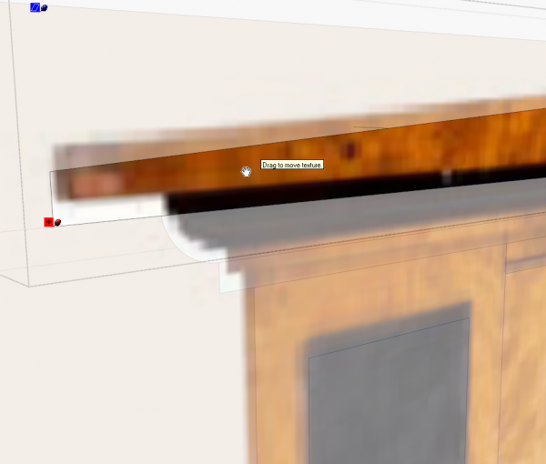
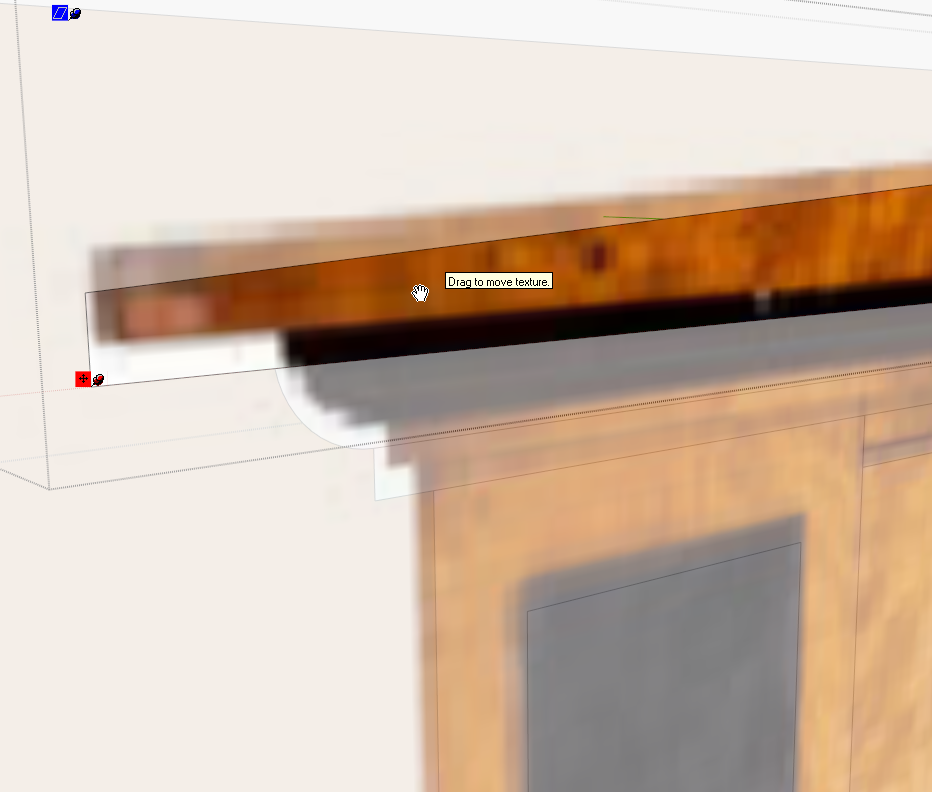
Right click on the face and choose Texture>Position. Then drag the material around to get the best fit. You might, in some cases, find that the material’s dimensions need to be tweaked slightly. Look for the green push pin and drag it in or out as needed to resize the image. Be careful because this green pin also rotates the material.
Some folks prefer to paint components instead of the faces inside. That might work in some cases but it eliminates the option to adjust the position of the material. Maintaining that control is one of the reasons I advocated opening components for editing before painting the,
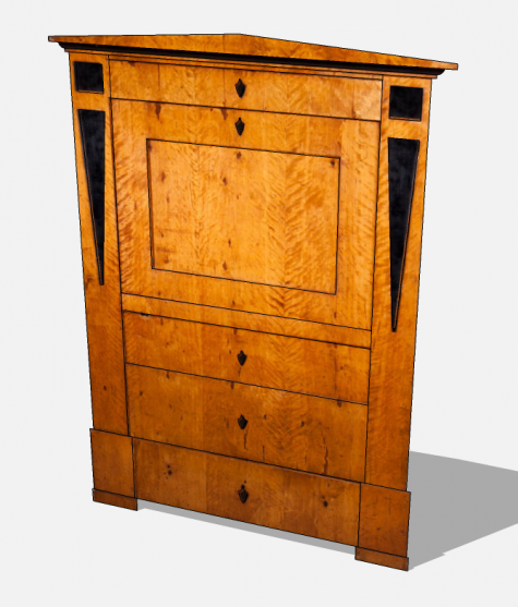
Continue working through the rest of the model tweaking the materials as needed. After painting and adjust the material for the pediment, I sampled of it for the black molding below it. Then, as I worked down the model, I sampled off the neighboring component I just painted.
Delete the face with the original material when you are finished with it and you’re done.



Log in or create an account to post a comment.
Sign up Log in