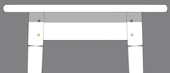
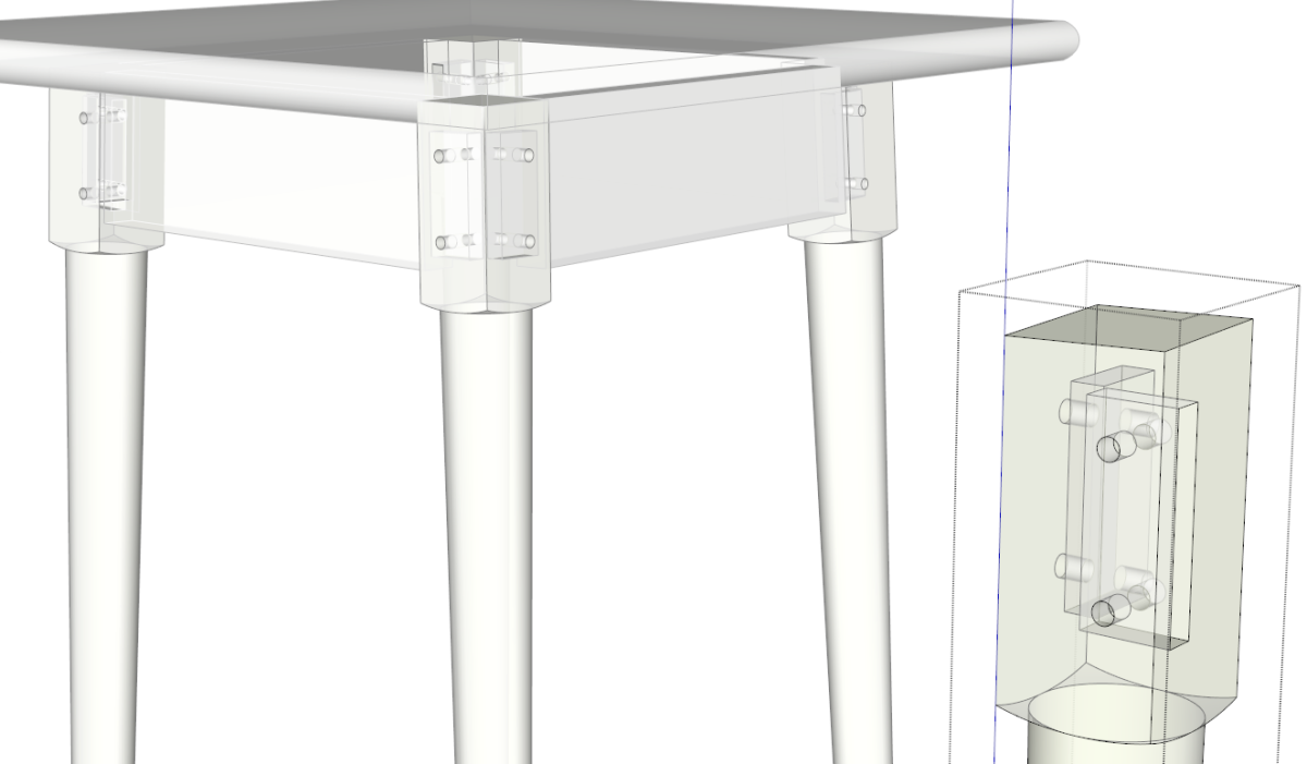
The other day I was working on a little table that has legs that splay outward from the corners. I had the table nearly completed when I discovered I needed to add pegs to the legs to retain the aprons. Now, I could have drawn a peg, made it a component and then worked my way around the table to get a peg in each of the sixteen holes but I didn’t want to spend the time doing that. I thought of several other options I could have used to do this. Here’s the one I chose.
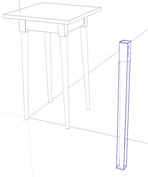
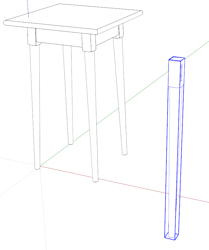
Normally I would just do this work on one of the existing legs but to help clarify what I’m doing, I dragged in a copy of the leg component from the Components browser found under the Window menu.
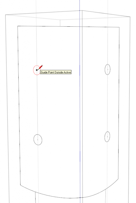
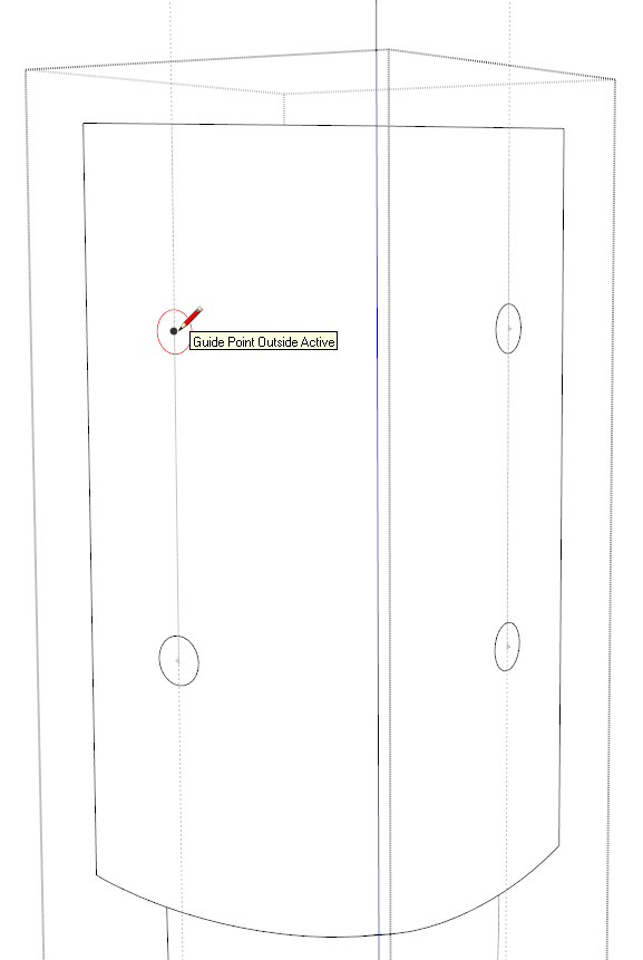
First we need some holes into which the dowels can be inserted. I set out a couple of guidelines and guide points with the yellow Tape Measure tool and then, with the component opened for editing, used the Circle tool. to outline the holes.
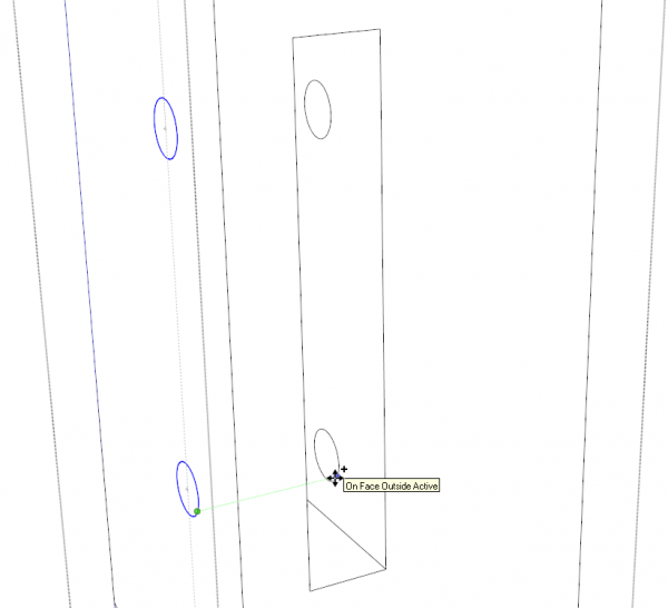
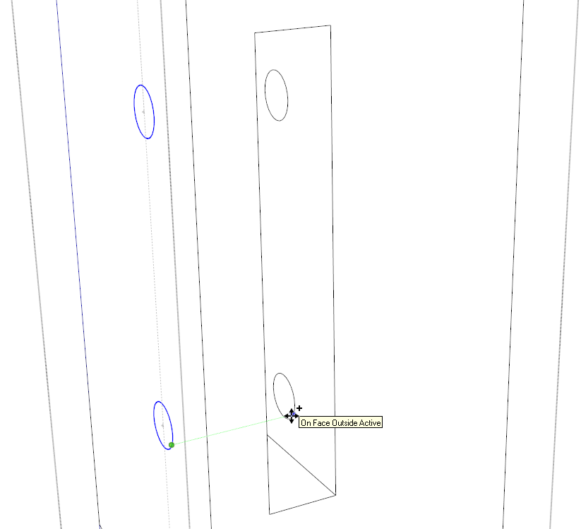
To continue the holes on the other side of the mortises, I copied the circles inward. It’s important to make sure you keep the copies lined up with the originals or the hole won’t go straight across the mortise. In the image above I was able to copy along the green axis for this.
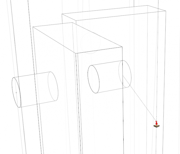
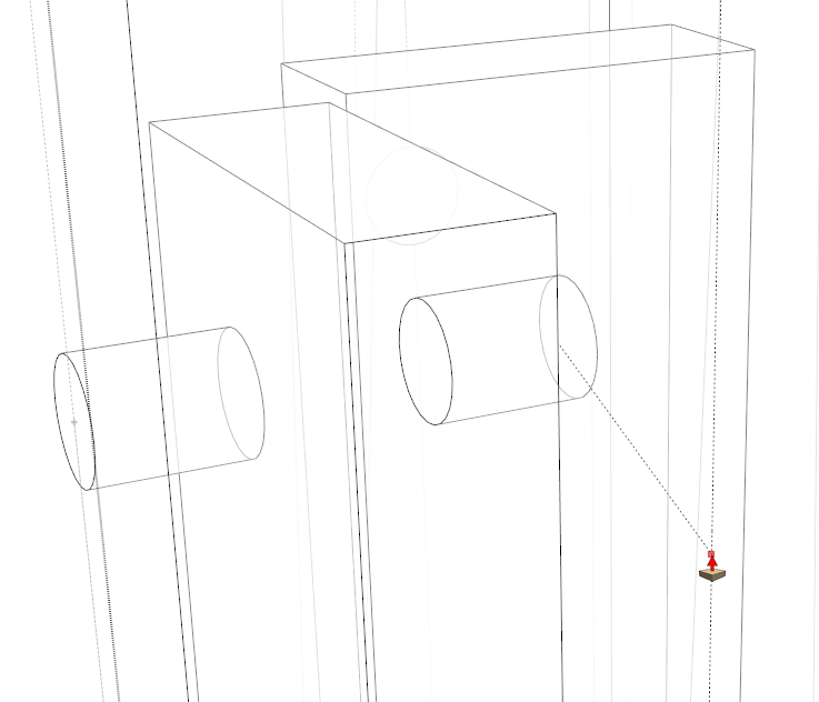
Push/Pull makes quick work of the holes. To get the depth right, I set out a guideline on the outside face to use as a reference. Here we’re looking at the model in X-ray mode although for things like this I generally don’t bother making that change. With practice you get familiar enough with the program to know what it is doing without having to see it.
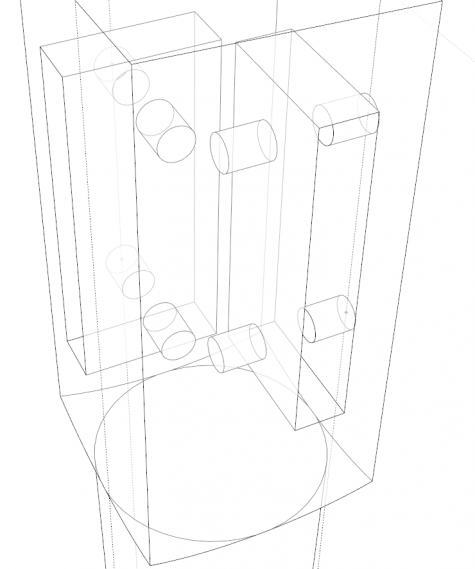
Now all the holes are created. It’s time to create the dowels.
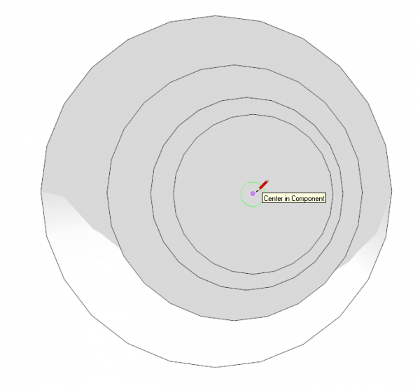
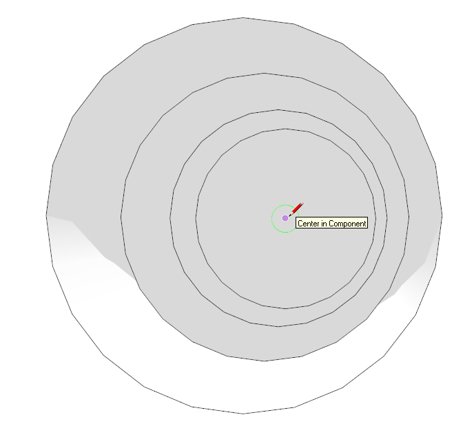
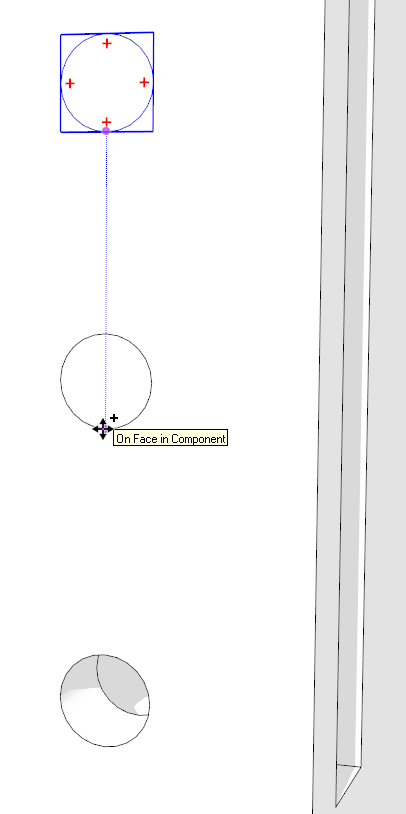
I clicked in space with the Select tool to close the leg component. Then I orbited and zoomed so I could look down one of the holes. I got the Circle tool and then used Inferencing to find the center at the bottom of the hole. To do this hover for 2 seconds (don’t click) over one of the vertices at the edge bottom of the hole. Then move the cursor toward the center. When it gets close it’ll snap to the center. the dot will become circular and a note will pop up indicating you’re at the center. Click and then drag out to one of the vertices on the edge of the hole.
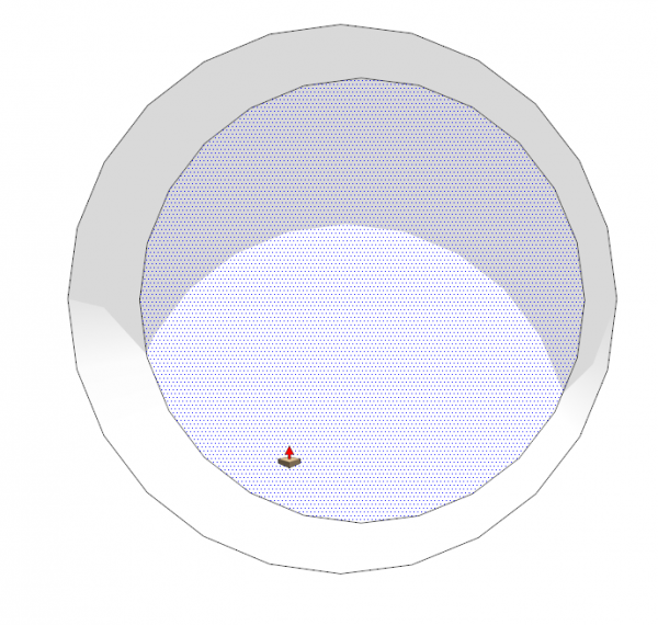
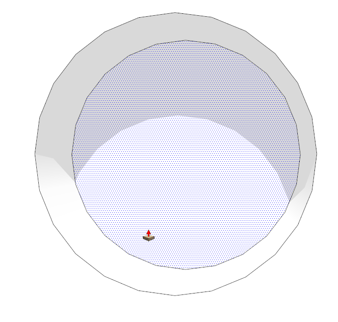
Use Push/Pull to pull the circle out flush to the surface of the leg. Then get the Select tool (use the Spacebar) and triple click on the peg geometry to select all of it. Hit the G key to Create Component. Give it a name and hit enter.
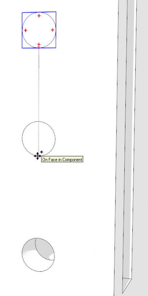
Next I used Move/Copy to copy the peg to the other hole on the same face.
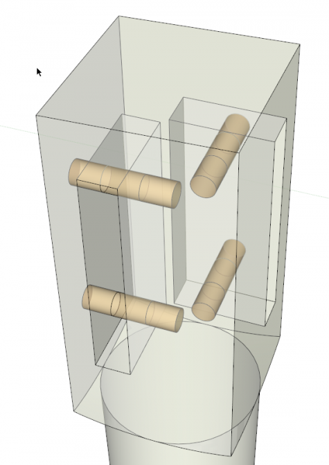
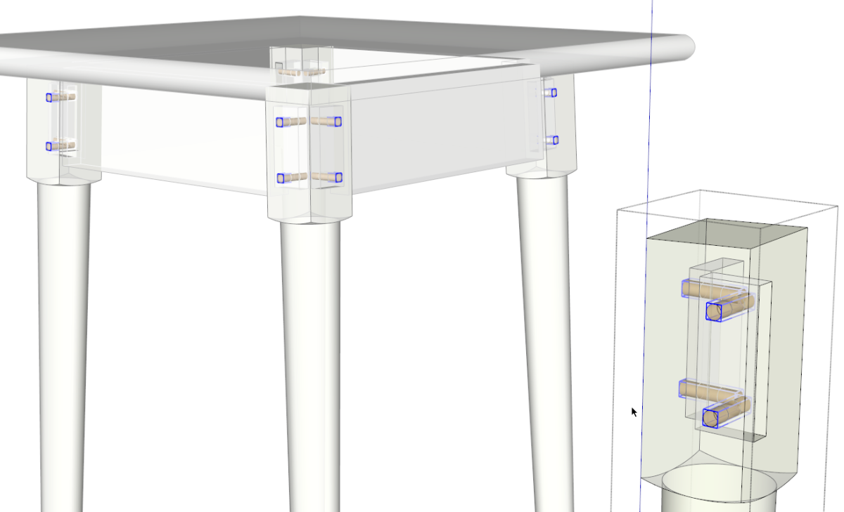
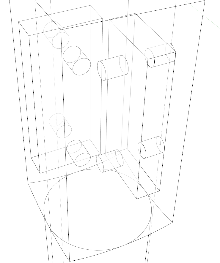
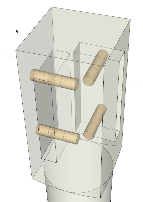
We could use Rotate/Copy to make the other two dowels but I didn’t feel like locating the center of rotation so instead I made a different peg component for the other two holes using the same method as I used for the first two. In the image above I’ve colored the pegs brown so they would be easier to see. At this point I have the four pegs in the fifth leg in the model but none in the legs that are actually part of the table where I need them. Here’s where I’m going to apply a little mechanical advantage, so to speak.
The leg is already a component so when I put the holes in the copy I’ve been working on, I know the holes got put into the other four. I’m going to use that same power to insert the pegs.
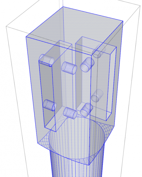
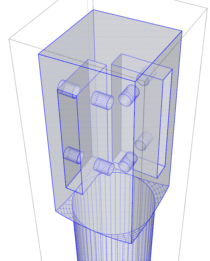
I selected the four pegs and hit Ctrl+X for Cut. Edit>Cut, the Scissor icon on the Edit toolbar also work. On Mac the keyboard shortcut is Command-X. Then I selected the leg component and in Entity Info (Window menu) I changed the definition name. It doesn’t really matter what the change is because we’ll discard this component shortly. Then I opened the leg component for editing and, using Select, I triple clicked on the geometry to select all of it.
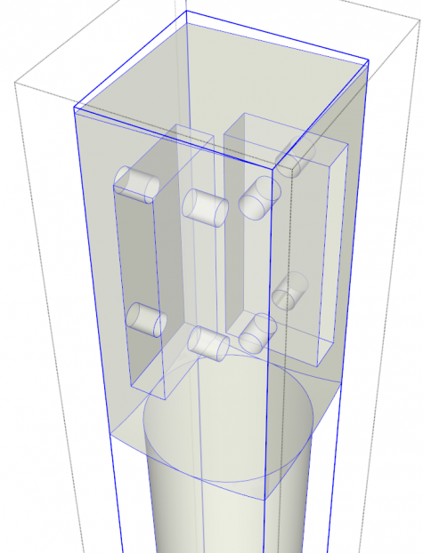
I hit G to Create Component. I called this component “Leg” and hit Enter. For those who are familiar with my sandwich and cling wrap analogy for components, we now have our leg geometry double wrapped. Normally this isn’t recommended for a single part.
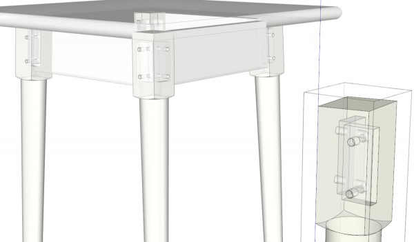
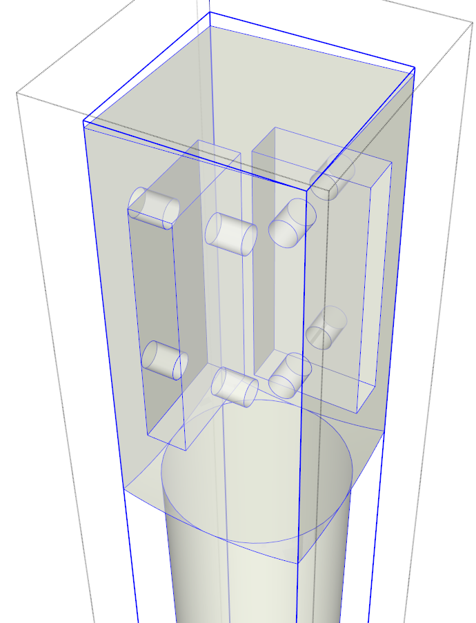
So here we have all five legs “double wrapped.” With the fifth leg component’s outer wrapper still open for editing…
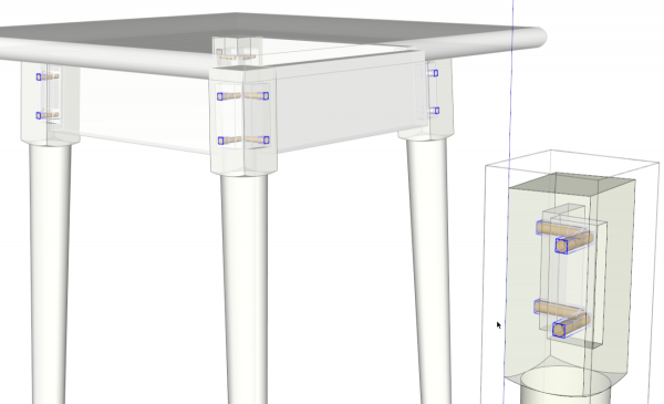
…hit Edit>Paste in Place. Presto! There are pegs in all the holes in all the legs.
At this point the legs with the pegs are what we call nested components. In this particular case I don’t want nested components in this model so the next step would be to select all of the leg assemblies, right click on one with Select and choose Explode. This will remove the outer wrapper leaving me with the pegs and the legs as components but not nested together.
The extra leg can be deleted and then Unused components can be purged from the In Model component library.
This looks really involved but it is actually quite easy and fast to do. There’s little measuring required because the existing parts of the model are used as much as possible.
You might find many other ways to use this same idea to save yourself some work and time when you are drawing.



Comments
Thanks for posting this. In the past, I have had a hard time with this process.
Jeff, I'm glad this helped you with the process. You could use essentially the same process to build drawers behind drawer fronts or perhaps create other assemblies.
-Dave
Log in or create an account to post a comment.
Sign up Log in