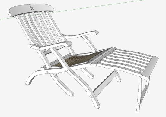
Handling curved back slats on a chair, bench, Adirondack, or settee can be a challenge in SketchUp. Getting them properly positioned, spaced, and angled between the lower rail and the crest rail can be a frustrating exercise. I ran into this while recently re-constructing the Titanic Deck Chairs.
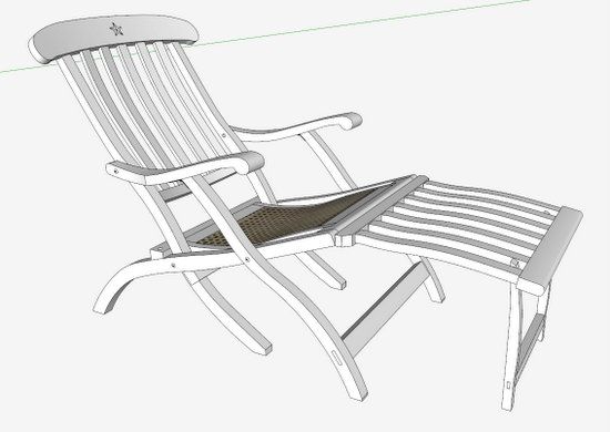
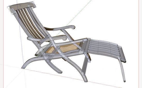
Here is the overall model that I’ve developed in SketchUp. Note the five back slats, twisted and angled but evenly spaced.
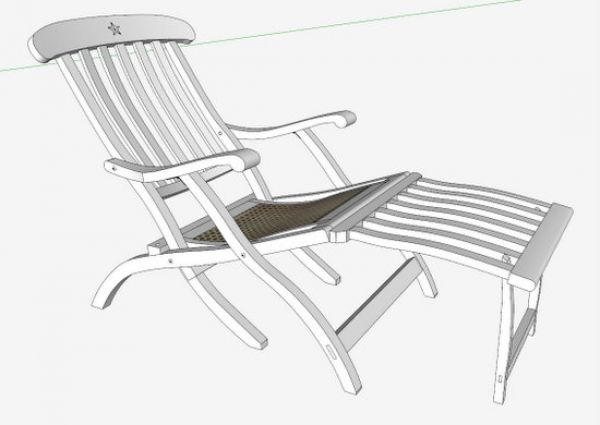
You can incrementally nudge the slats in 3D space using Move/Copy and Rotate Tools, but I find this method to be inefficient, and less accurate. I like to have a more determinate way of connecting and positioning.
My method basically makes the curved slats into components that act like straight turned spindles. These components are rather easy to orient within Windsor chairs for example, so I’ve adopted the spindle method for curved rectangular slats. I’ll show you some of the major steps in doing it this way.
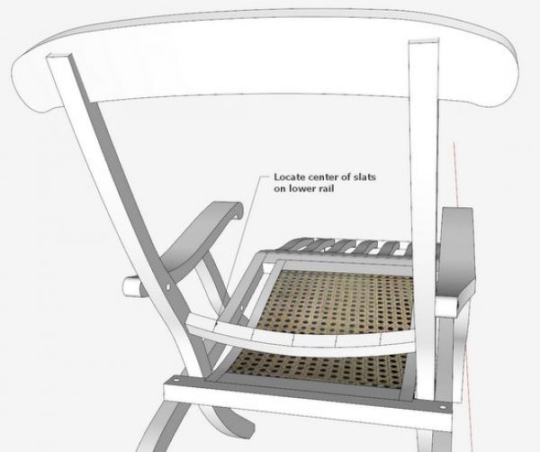
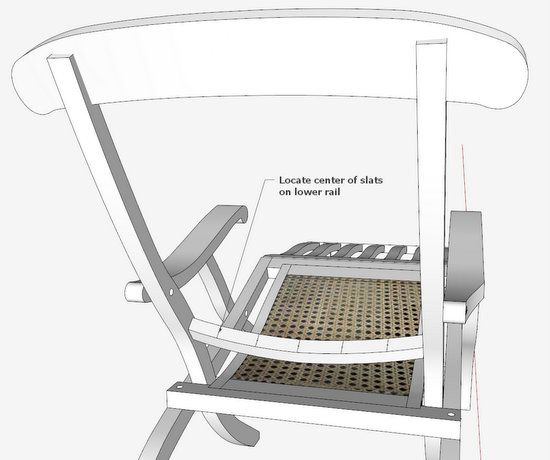
Step 1: Locate evenly spaced centerlines for the slats as they enter the lower rail. This can be done by creating a divided line on which vertical faces are spaced. The faces then intersect the curved rail at the center of the slats.
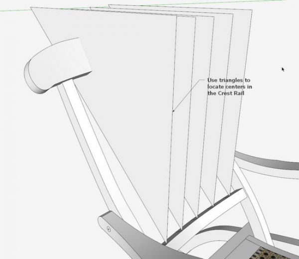
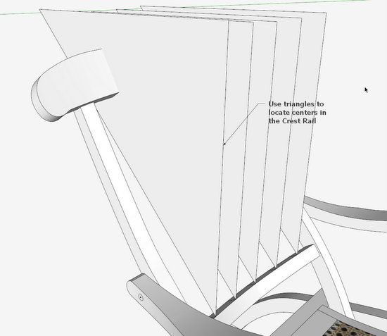
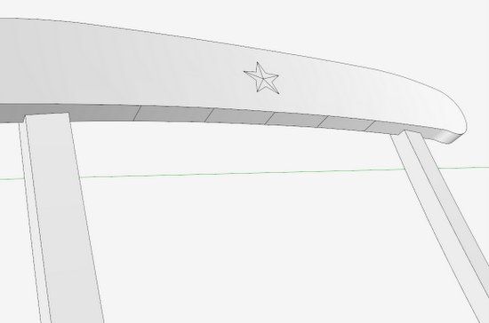
Step 2: Using the center locations on the lower rail, make vertical triangles that intersect with the Crest Rail. Select the lower edge face of the Crest Rail, and Intersect with Model. After Intersection, the resulting lines locating the center of the rails are shown below.
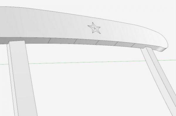
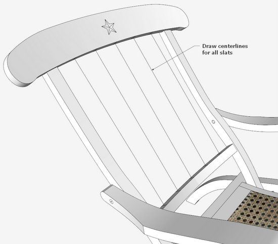
Step 3: Draw lines between the centers of the Crest Rail and the Lower Rail. These are the centerlines for the slats.
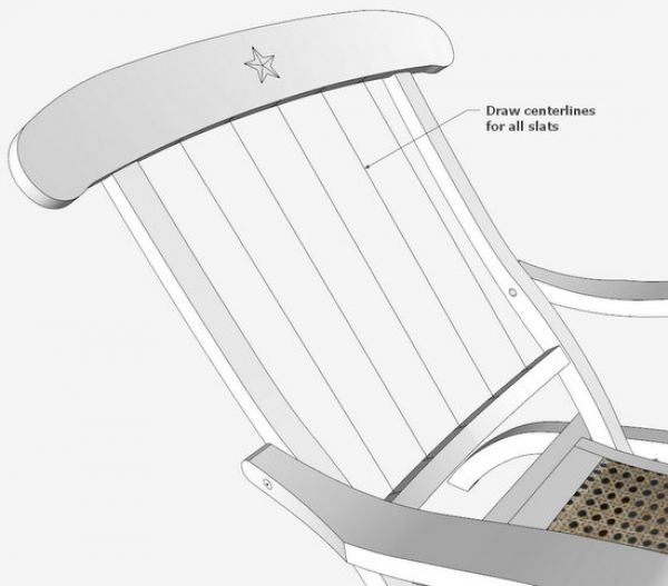
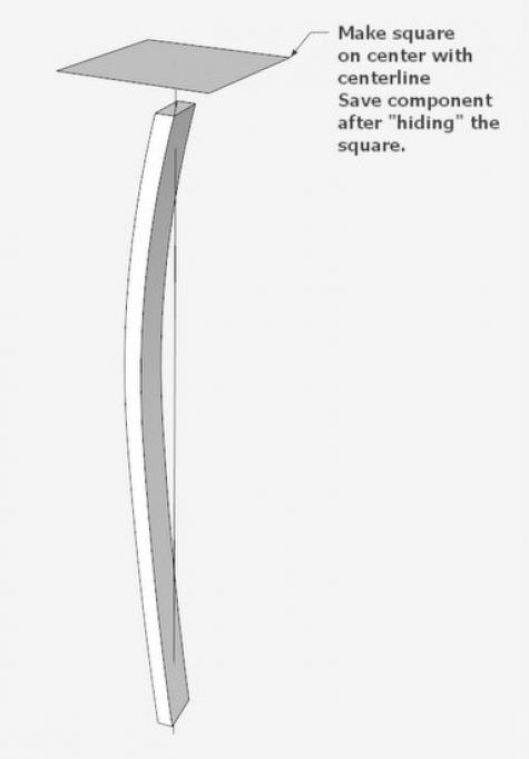
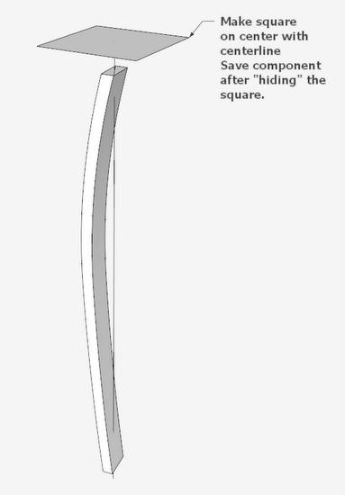
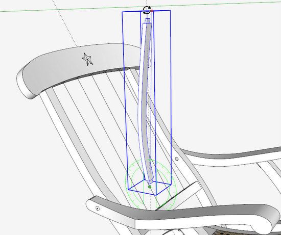
Step 4: Create a centerline for the slat within the component definition. Make a diagonal on each end of the slat and connect the midpoints to make the centerline. Rotate the component so that the slat centerline is on the blue axis. Make a square face on the red – green axes and centered on the centerline. The square needs to be within the definition of the component. “Hide” the square so that it does not show in the model.
The square makes the component act as if it is a turned spindle. It will rotate on the centerline. If the slat were straight, there would be no need for the square.
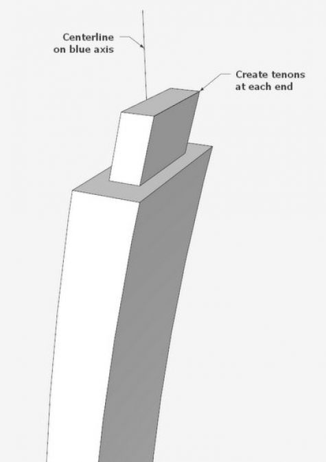
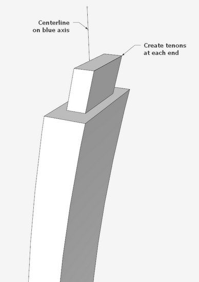
Step 5: Make the tenons on the ends of the slat.
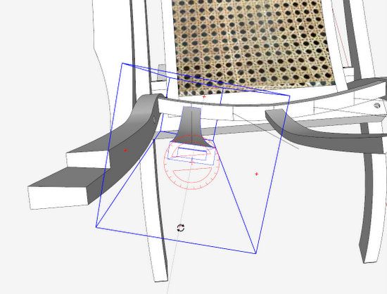
Step 6: Bring a copy of the slat over to the assembled chair. Connect the end of the slat centerline to one of the chair back centerlines as shown below. Select the slat and pick the rotate tool. Snap the rotate tool on the connection of centerlines. Make sure to have the proper orientation of the Rotate Tool – green color as shown below is proper in this case.
Start the rotation of the slat by clicking the Rotate Tool on the upper slat centerline, then moving toward the back. Stop the rotation when reaching an “in-line” guideline extending from the back centerline.
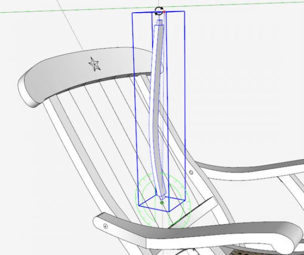
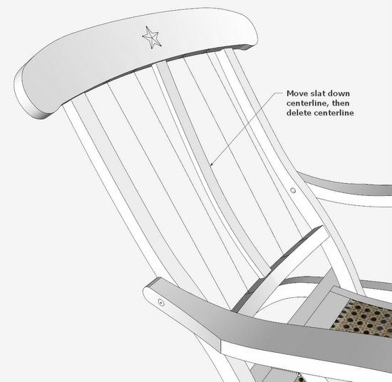
Step 7: Use the Move/Copy Tool to shift the slat down to final position. Holding the Move/Copy Tool on the back centerline ensures that the slat moves directly toward the center location at the lower rail. Then delete the back centerline.
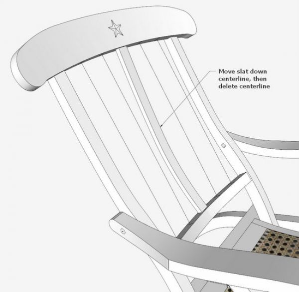
Step 8: Some of these slats will require a rotation to match up with the curvature of the lower rail and crest rail. This is easy with the Move/Copy Tool, since the slat has been made to rotate on its centerline like a straight turned spindle. I have temporarily “hidden” the Crest Rail in this scene so I can see the rotation.
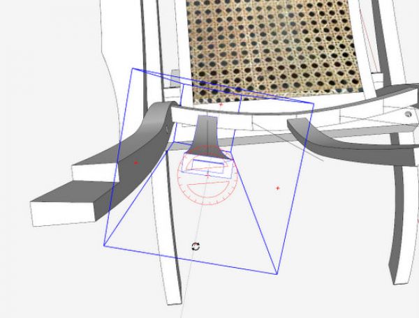
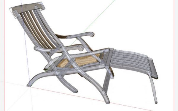
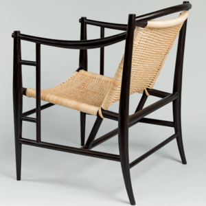
By the way, I’ve tried to accurately model the original deck chair using a photo from the Internet. I imported the photo as “Use as a new matched photo”. I couldn’t find a straight-on side view, so I used a perspective image. Since this piece is non-orthogonal, the Photo Match introduces error. But I think I’ve got a reasonably close match.
Here is a view of the Photo Match on my SketchUp screen. This is an X-ray view so you can see some of the components roughly positioned and shaped over the dark mahogany photo.
Tim




Log in or create an account to post a comment.
Sign up Log in