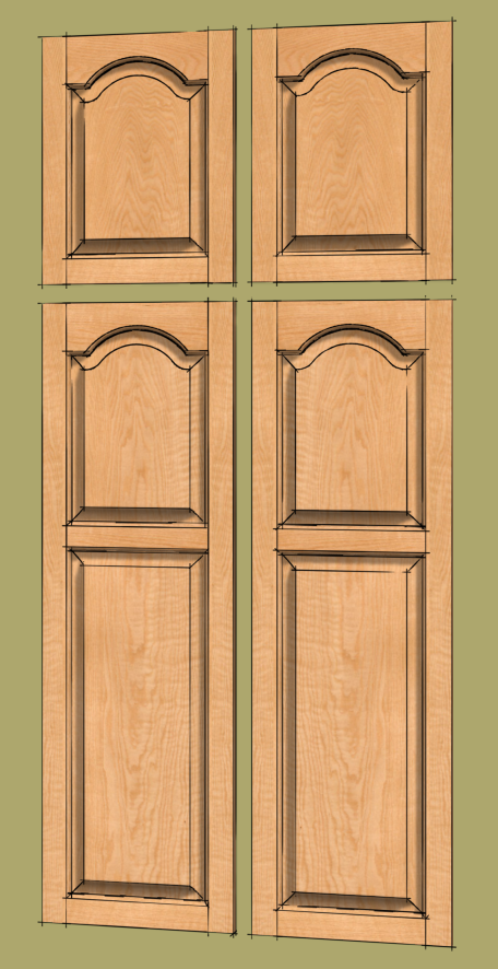
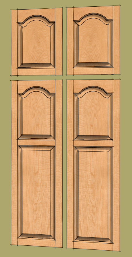
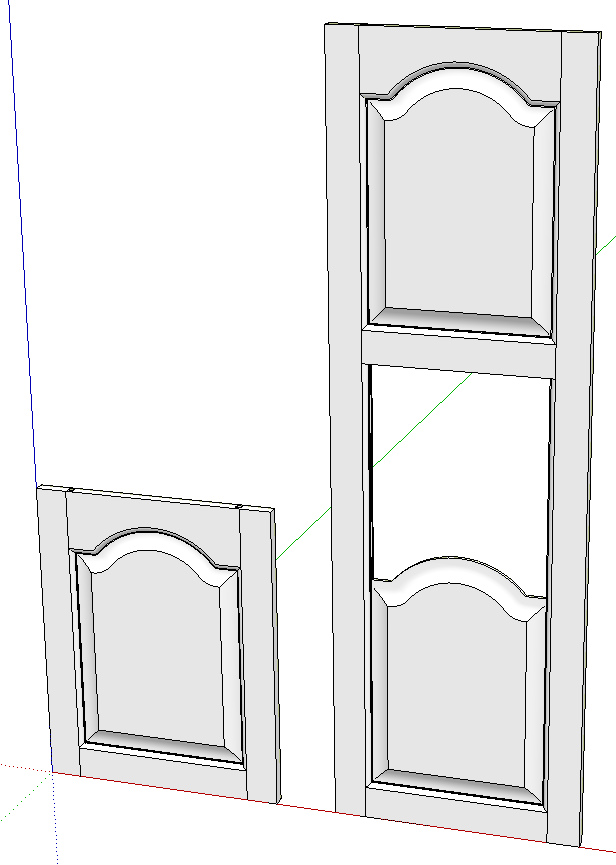
The other day a fellow asked about drawing frame and panel doors with arched or cathedral panels for a pantry cabinet he is designing. He is planning to have some tall doors at the bottom and a couple of short ones above as in the image, above. Here’s a method for creating them. In this example I’m drawing all of the parts as individual components so an accurate cut list could be created from them.
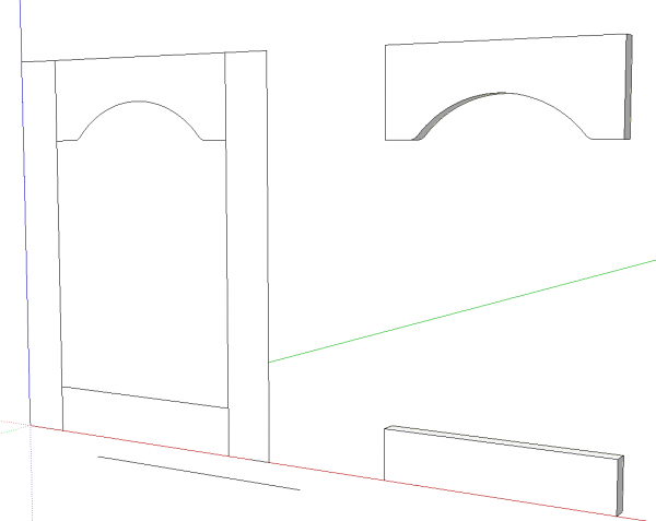
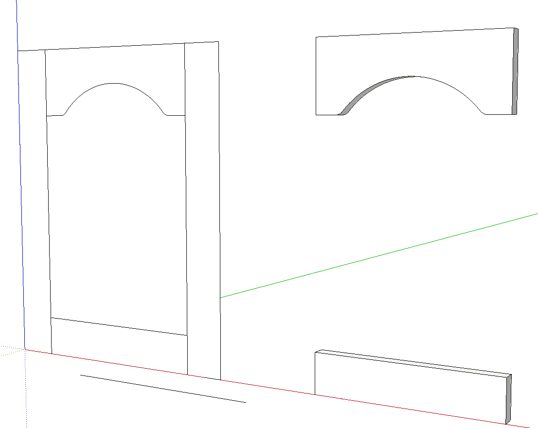
I started with the 2D version on the left while I worked out the curve for the top rail. I don’t have any of those router templates to measure so I just eyeballed the curve and drawing it on a 2D version of the door made it easier to see if I got something that is acceptable. If you are using a commerically available template you could measure it and create a very precise model or you could use the curve you draw to create your own template.
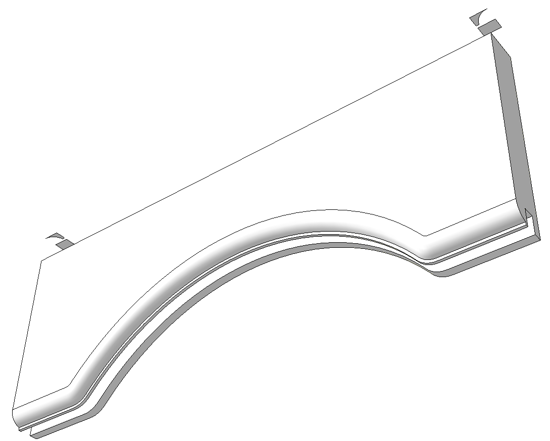
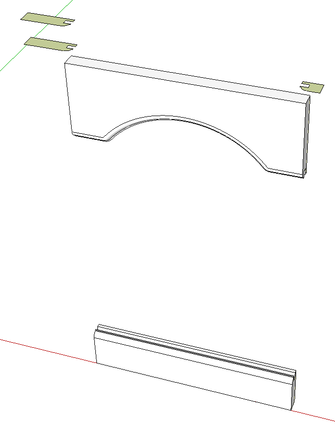
After getting the curve I wanted, I copied the faces representing the rails over to the right and used Push/Pull to give them thickness. Before running Push/Pull on the top rail, I selected all of the curve and used Weld to convert it to a single entity. You might be inclined to make components of these parts at this stage but I waited until I had them completed. This allowed me to work on both rails at the same time.
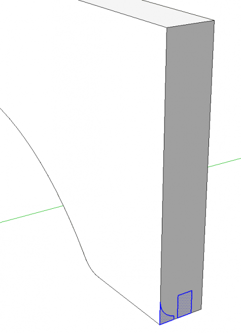
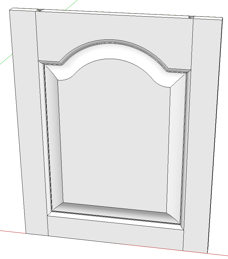
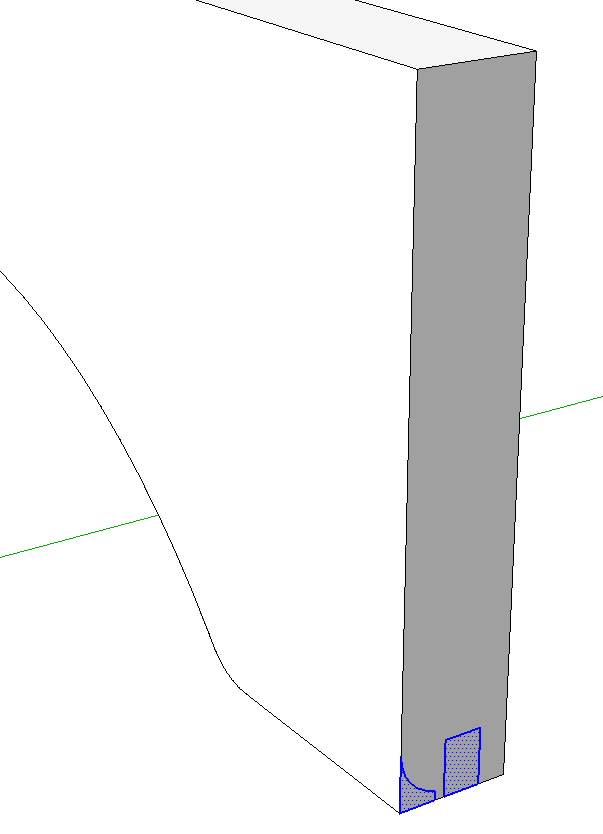
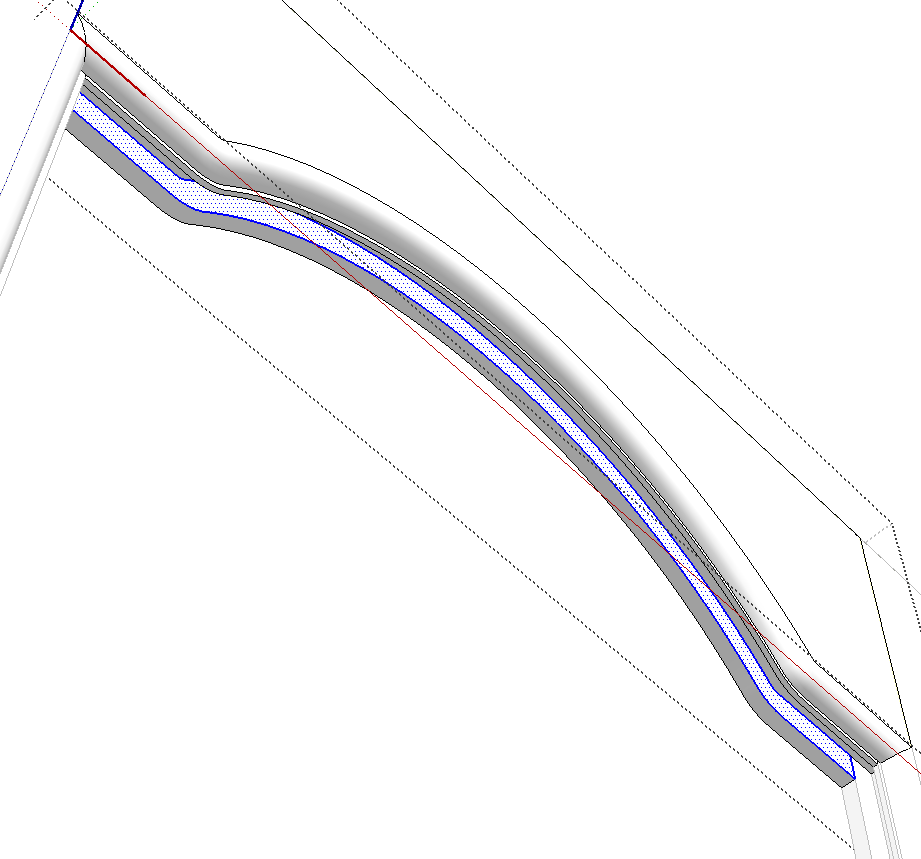
I extended the length of the rails by 3/8 in. on each end using Push/Pull. Then I drew the groove and edge profiles on the end of the top rail.
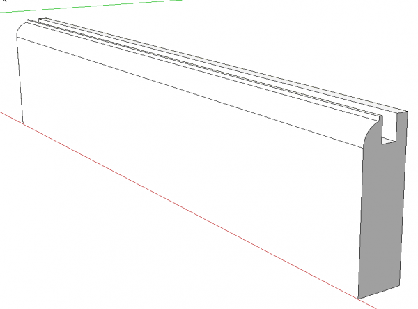
I copied the profiles using Move/Copy and moved the copy down to the bottom rail. They have to get flipped along the blue axis before being moved into place. Then I used Push/Pull to cut the groove and edge profile.
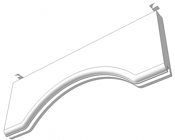
I also made a copy of the profiles and placed it above the top rail and copied it to the opposite end. This last copy got flipped along the red axis.
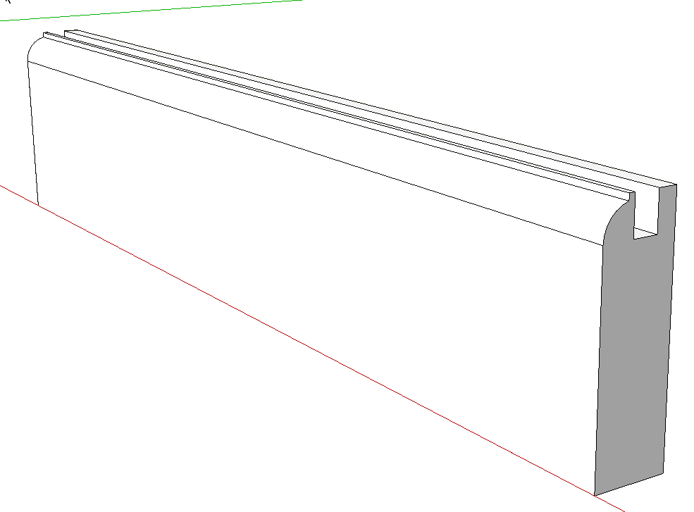
Then I selected the bottom edge of the rail and ran Follow Me to create the groove. After that I repeated the process for the edge profile.
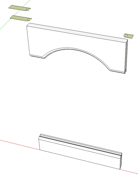
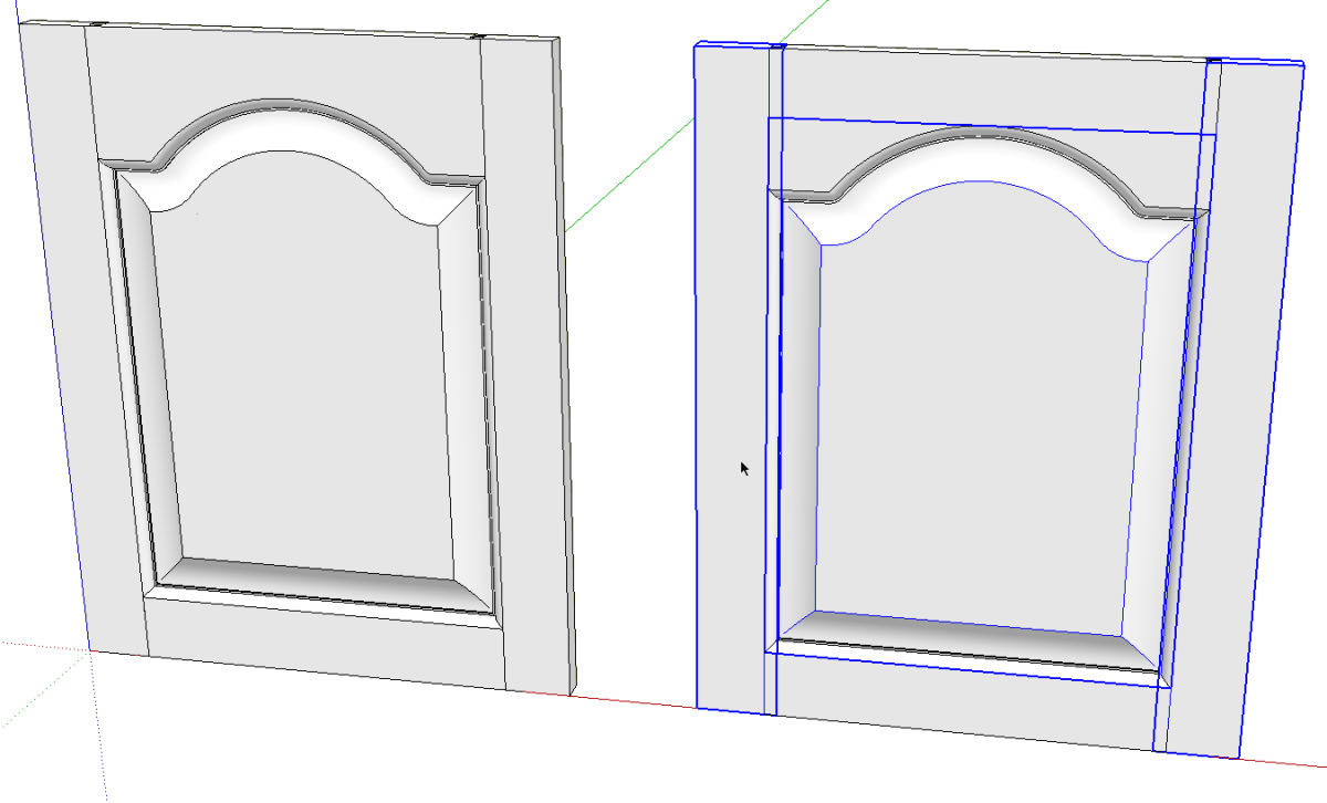
So here are the two rails. Above the top rails I converted the profiles I drew before into mirror images. The one on the left I drew to the dimensions of the stile and made a copy of it straight above. This gives me a cutter and a face from which to make the actual stile. To create the mirror image I drew a rectangle and then deleted the appropriate edges. The cutter on the right isn’t drawn to the full width of the stile but it doesn’t matter.
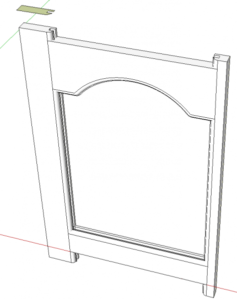
I used Push/Pull to push my cutter profiles down through and slightly beyond the bottom rail.
Next we need to create intersections where the faces of the cutters pass through the ends of the rails. Select the geometry of both the cutters and the rails, right click on it somewhere and choose Intersect Faces>With Selection.
After the intersections are completed delete the stuff that isn’t rail and correct the face orientation as needed.
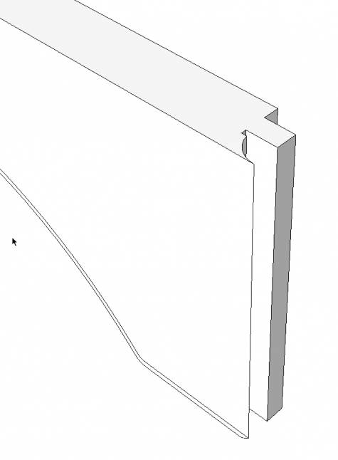
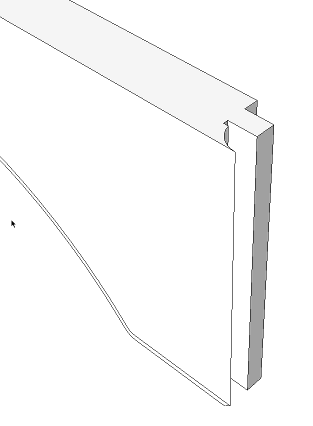
Here is the end of the top rail with the cope joinery cut. At this stage make a compoent of each rail. Select the geometry of each one in turn and make it a component. Don’t make the mistake of selecting all of the geometry of both rails at the same time and making a component of that.
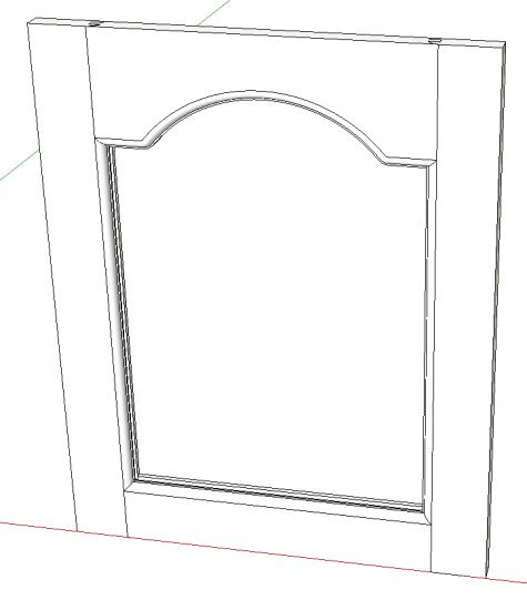
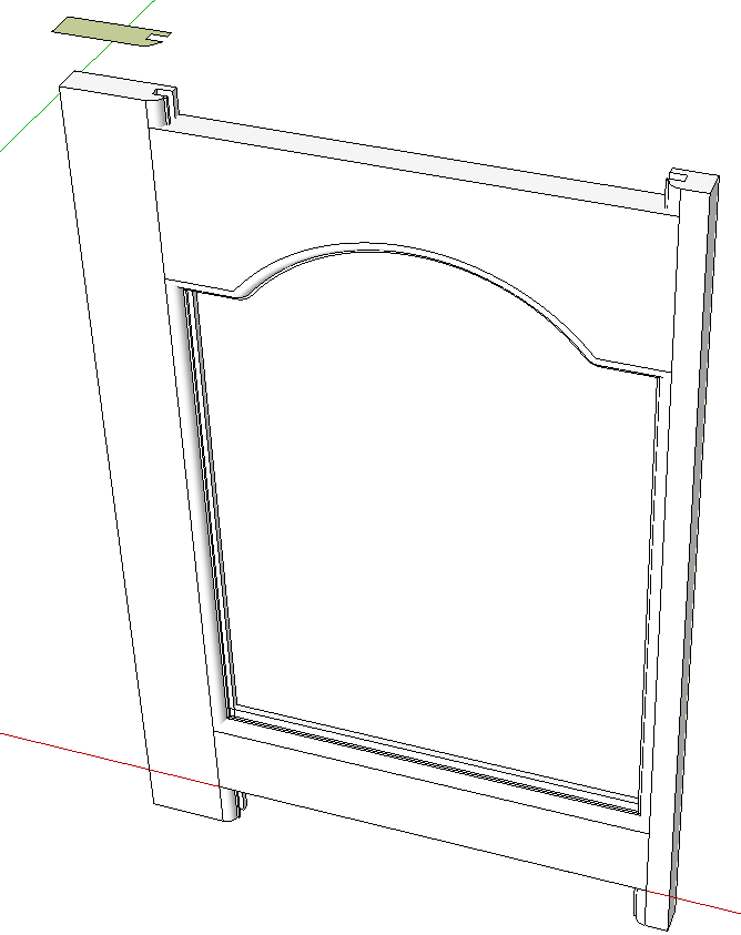
Push/Pull makes the left hand stile. It is made into a component, copied to the right with Move/Copy and the copy flipped along the red axis. The frame is complete. Now on to the panel.
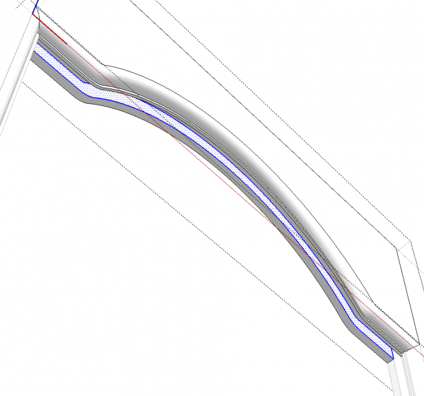
We could trace the curve for the top of the panel but here’s an easier way. Open the rail for editing and, with the Select tool, double click on the back face of the groove. Copy the selection with Edit>Copy, the copy button on the Edit toolbar, Ctrl+C or Command-C on the Mac. Then click outside the component to close it and hit Edit>Paste in place. I use this function so much that I have created a keyboard shortcut for it.
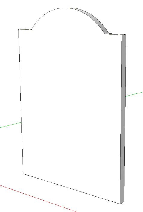
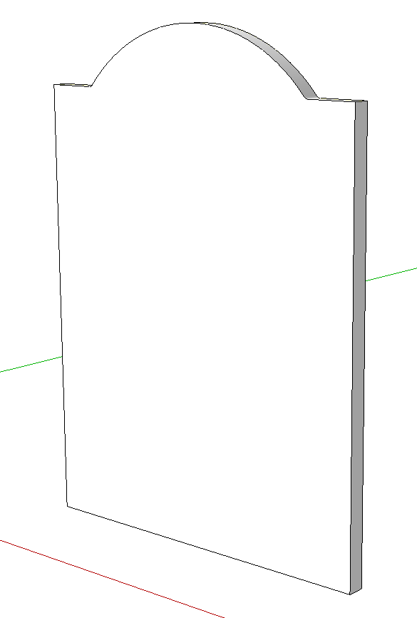
Complete the borders of the panel by tracing around the inside of the grooves of the stiles and bottom rail to get a face. Hide the rails and stiles temporarily. Weld the top curve and then use Push/Pull to give it thickness.
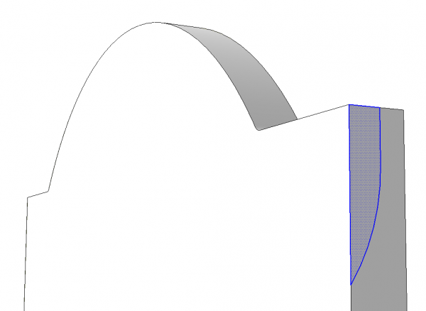
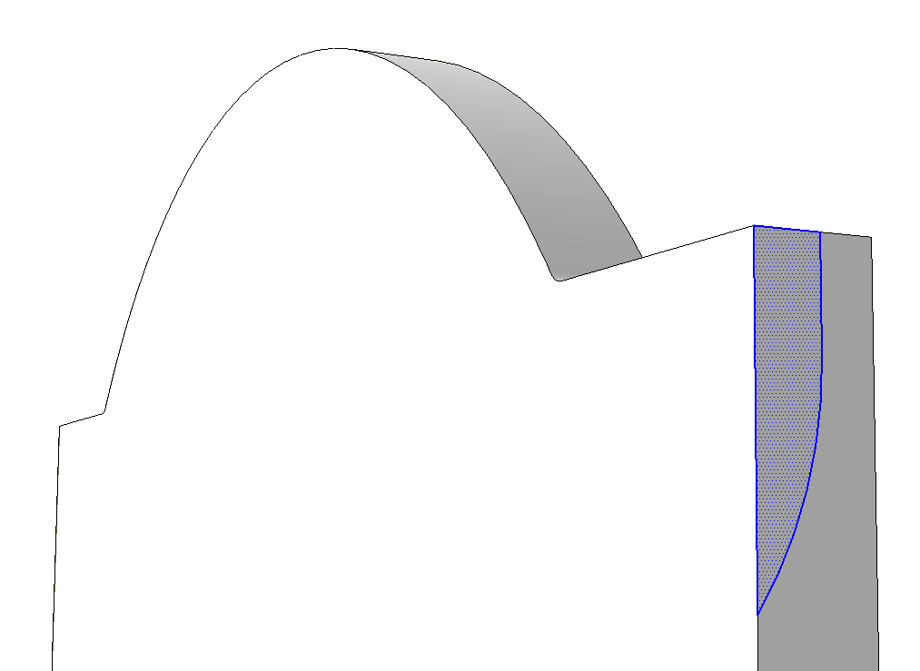
Zoom in close to an edge of the panel and draw the profile of the raising.
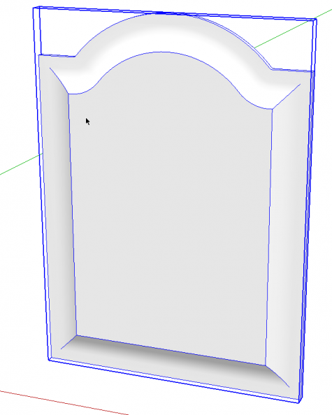
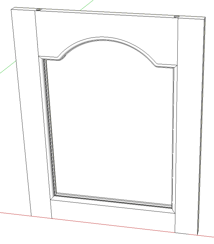
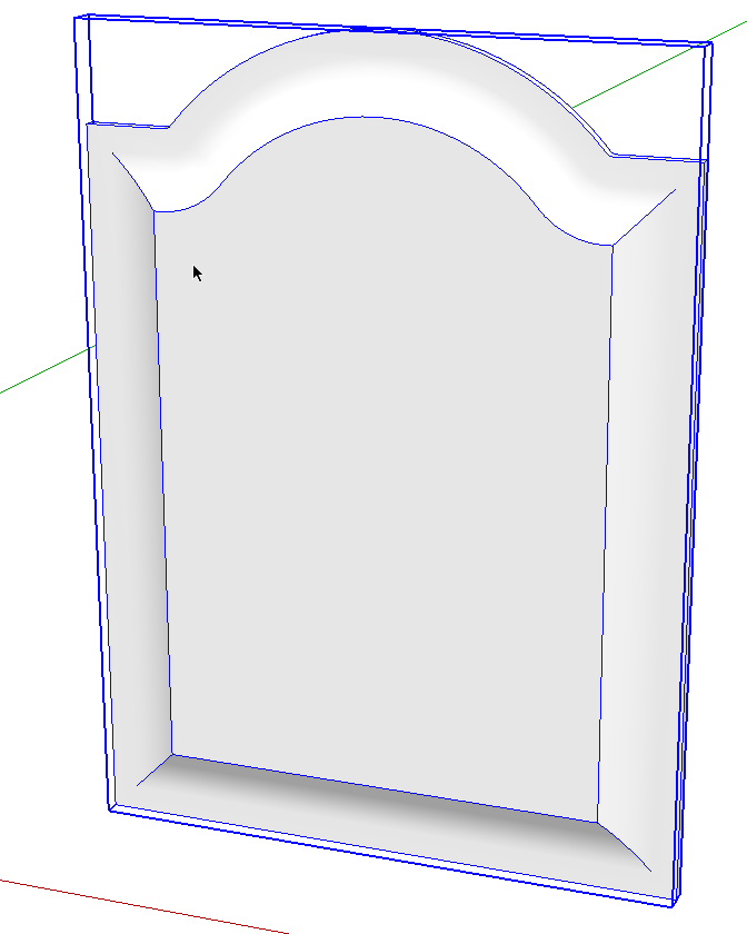
Run Follow Me and then make a component of the panel.
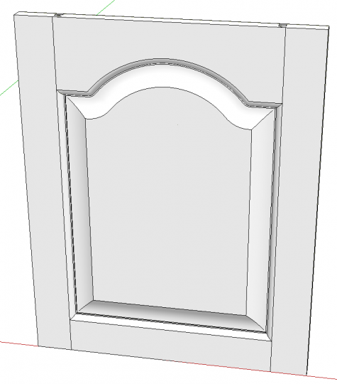
Unhide the rails and stiles and the top door is completed.
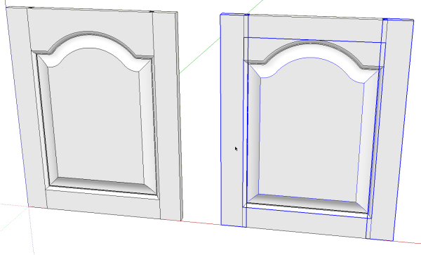
Now on to the bottom door. Make a copy of the top one using Move/Copy. In this case the rails will be the same as on the shorter door but the stiles and panel will get modified so they are selected and made unique.
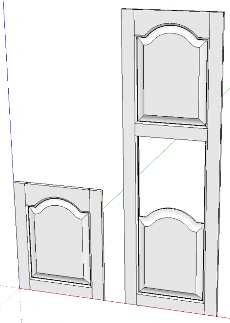
Move the top rail up to the correct height. Copy the bottom rail and panel up by the same distance and open one of the stiles for editing and use Push/Pull to stretch the stiles to the desired length. Make the copied rail and panel unique.
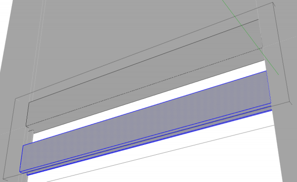
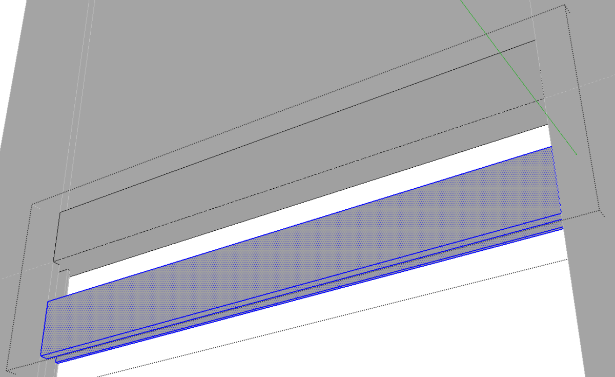
Open the intermediate rail and use Push/Pull to reduce the width of the rail to half. then select all of the geometry and copy it down as shown above. While it is selected, right click on it and choose Flip Along>Blue Axis. Move the flipped geometr up so it contacts the original geometry and delete the seam line down the middle. Close the component for editing and check your bototm rail to make sure you actually did make the middle one unique.
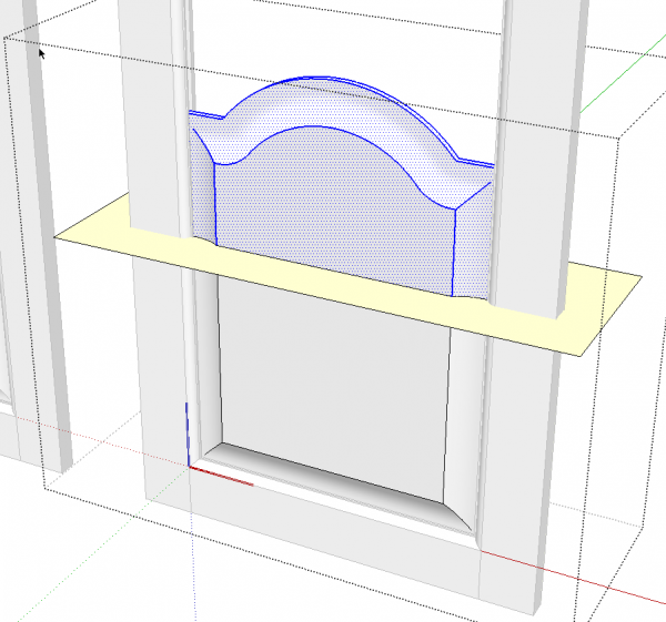
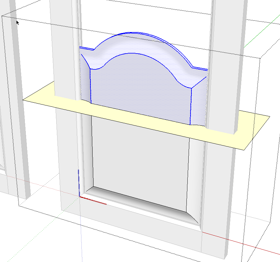
Open the bottom panel for editing and draw a rectangle through the panel. Intersect the rectangle with the panel.
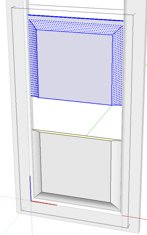
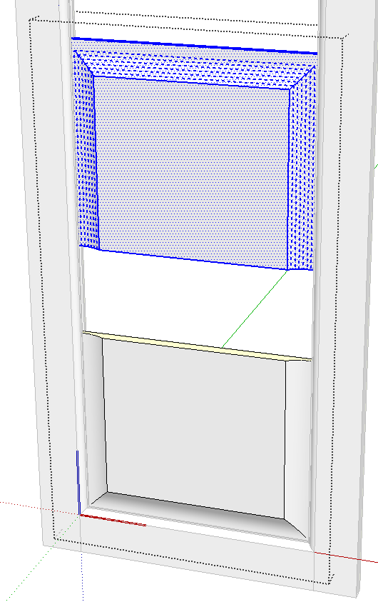
Delete the geometry above the rectangle and the outer edges of the rectangle. Then select the remainder and use Move/Copy to move it up. Flip the geometry along the blue axis and move it down to the bottom part. Delete the seam line and then select just the top part of the panel and use Move to stretch the panel up into the groove on the bottom edge of the intermediate rail. You might find it easier to do this if you hide one of the stiles temporarily.
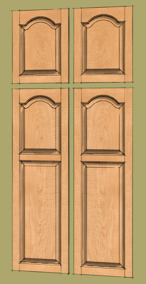
This probably sounds very complex as you read it but if you are familiar with using the Move/Copy function, it all goes quite quickly.
At this point we can make doors of any height with just the components we have. All of the components except the top rail and arch-topped panel could also be used to make doors of any other width using the same methods I demonstrated when I converted this fern stand to a bench. Because of the curves, the top rail and panel can’t easily be modified much without changing the proportions of the groove and profiles. But you could copy the top rail, keep the joinery at the end and just redraw the curve, groove and edge profile so you don’t have to redraw everything.
Make sure you save these components for later use.
Happy New Near!



Comments
Dave: For wider panels what I have done is separate the top rail into an arch section that ends just after turning horizontal and 2 end sections that are all horizontal. (I have these saved as Components to reuse) The move the ends out to the new width and scale the center section in length only to fit up with the ends. Then make a new component and erase the junction lines . This may or may not be easier depending on your sketchup skills and what operations are easier for you.
Keith
Keith, that's an interesting approach however I believe it has a flaw. The top rail I drew could easily be lengthened by moving the joinery at the ends in the same way you describe. You could select just the geometry of the arch, too, and scale that but scaling the arch geometry is the problem. Using the Scale tool on the arch geometry will result in distortion of the edge profile and the shape of the groove. For a small amount of scaling it might not be noticeable but it wouldn't really be correct.
-Dave
Log in or create an account to post a comment.
Sign up Log in