Recently I had a discussion with a friend about modeling in SketchUp. We got to talking about things that create problems for users when drawing. These issues sometimes cause problems Here are a few things I see frequently in models that get sent to me or that I download from the 3D Warehouse and some tips to use in troubleshooting your own models.
There are several key tools you can use to help you in troubleshooting as you’re drawing. With SketchUp 8 components and groups are differentiated as “soild” or not “solid.” Components and groups are defined as “solid” when they are made up of edges that border exactly two faces. I check my components as I create them by keeping Entity Info open while I’m drawing. If, when a component is created it isn’t defined as a “Solid Component” I start probing to find the problem.
Another thing I look at is the dimensions of the component’s bounding box to see if it makes sense. I also tend to run cutlists periodically to check the overall dimensions of the parts I’ve drawn. I always draw with precision at 1/64″ although I don’t intentionally draw anything to 64ths. When I run the cutlist with precision set that high, I can very quickly tell if I might have issues. If I see dimensions in 64ths or dimensions with a tilde ‘~’, I go hunting to find out why.
Here are some examples of common problems and how to fix them.
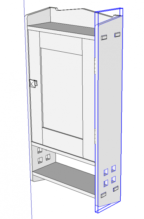
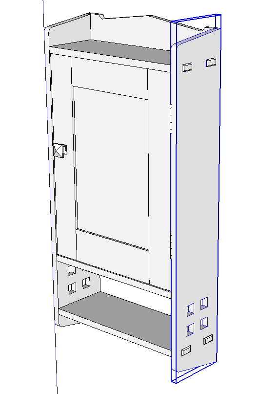
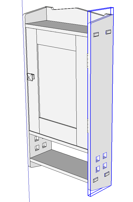
In this example the bounding box does not fit the case side as tightly as it should. This component doesn’t show as “solid”, either.
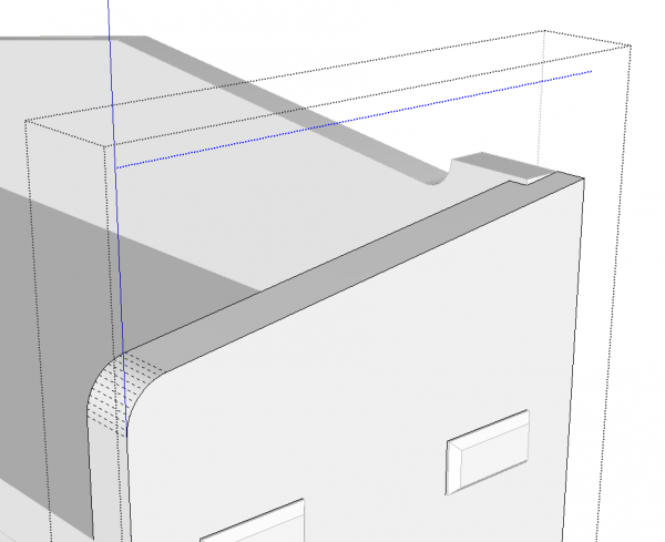
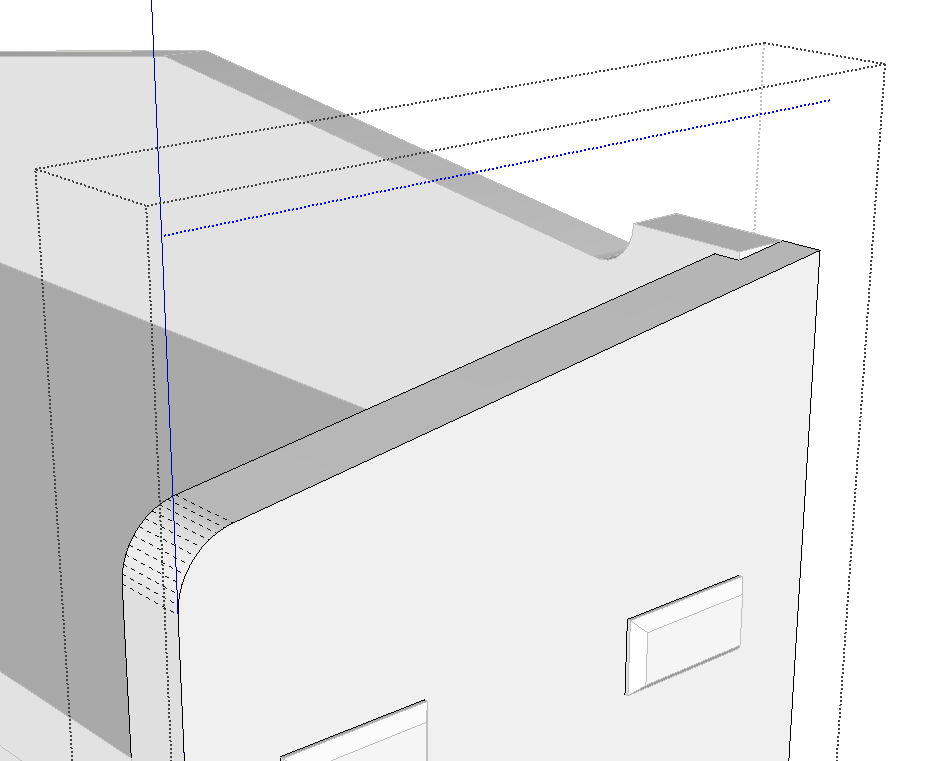
In this case, there’s a stray hidden edge in the component. I show it selected in this image. To find it you would need to turn on Hidden Geomtry under the View menu.
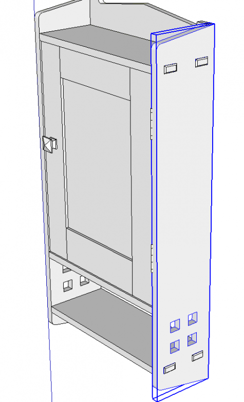
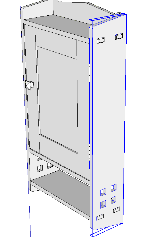
After deleting the hidden line the bounding box now fits tightly and the component will show as “Solid” in Entity Info. Sometimes that line might be a very short one attached to the other geometry in the component. You might have to look very closely to see that the bounding box doesn’t fit.
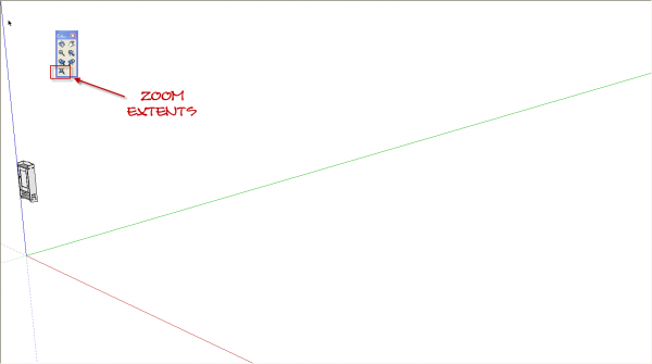
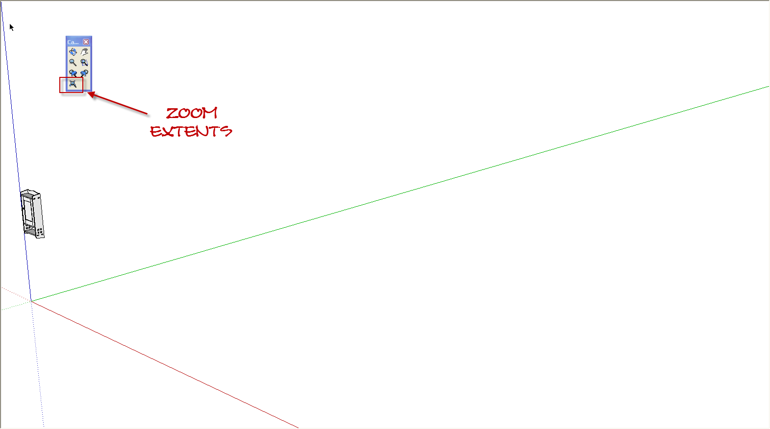
Speaking of stray lines, here’s an example of where a stray line may not cause a component to be un-solid. If you use Zoom Extents and your model seems to disappear or at least appear smaller than you think it should, there’s very probably a stray line somewhere at a distance from the rest of the model. You might not be able to see it on the screen but it is there. The way I deal with this sort of problem is to drag a right to left selection box over the apparently empty space and hit Delete. Then I click on Zoom Extents again and see if the model fills the drawing window as expected. If it doesn’t, I try again. Usually I do this with Hidden Geometry displayed because I sometimes find there’s more than one line segment hiding out there in space. By using a right to left selection box you only need to cover part of the problem geomtry to get it selected. Pay close attention to what is selected. If dragging the selection box over what looks like empty space results in a component in the model being selected, the stray segment is inside the component. Open the component for editing and go hunting to find the geometry to delete.
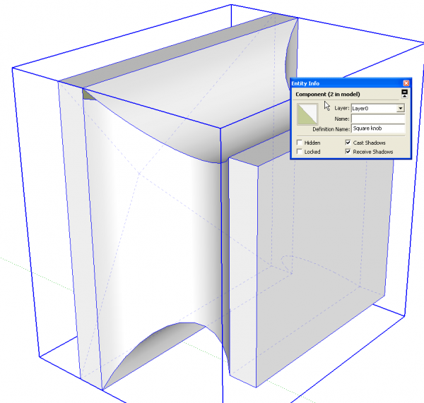
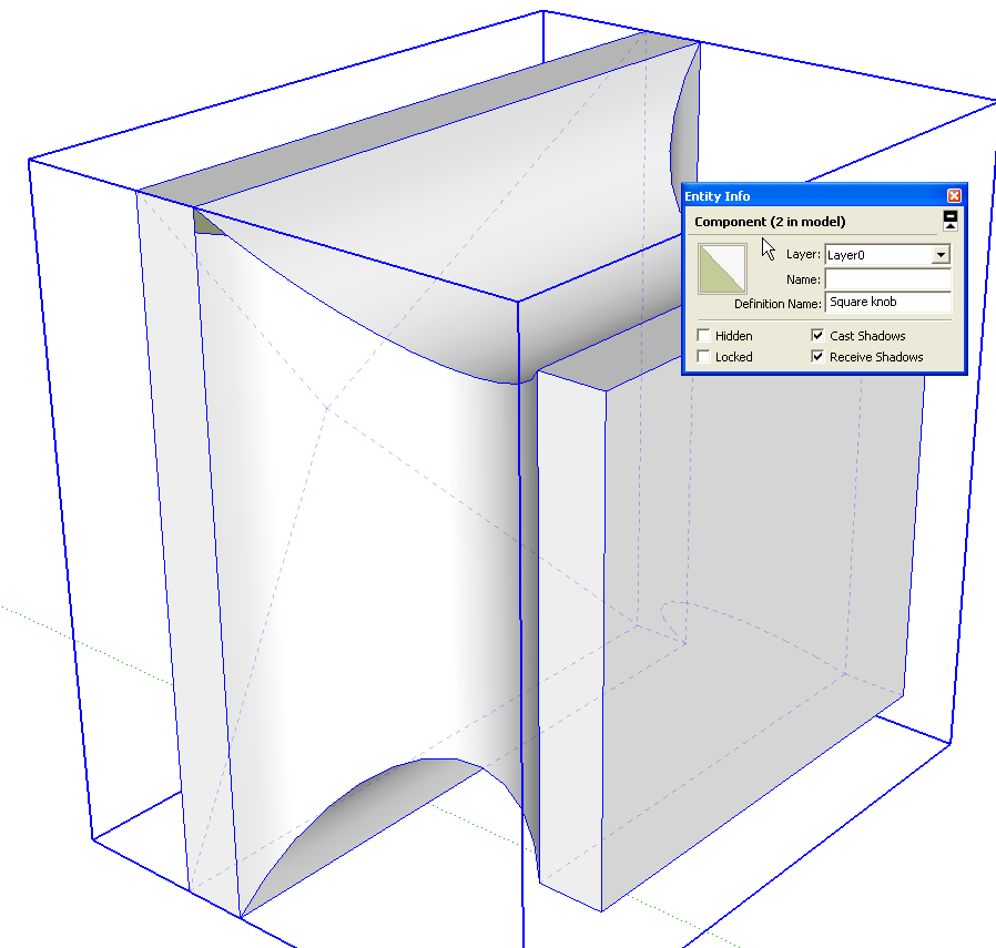
Here’s another example of a component that isn’t solid. This knob has a tiny hole in it. You can see it as a little green triangle. The component isn’t solid for exactly the same reason as the case side wasn’t. The edges of the hole only bound one face, not the two required for “solid” status.
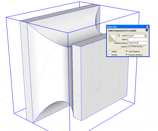
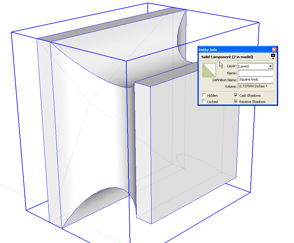
After tracing along one of the edges to heal the hole, the component shows as solid in Entity Info. SketchUp wonlt fill in very tiny faces so it might be that you need to scale the component up somewhat before trying to heal it. As I’ve shown before, I like to make a copy of the component off to one side of the model and scale that copy up by a factor of 100 or 1000. I do the repair work on that large copy of the component and when I’ve finished, I close the component to get out of editing mode and delete the big one. Since what ever you do to one component in the model gets carried through to the other instances, the correctly sized copies get fixed up, too. This also eliminates the need to put the component back in it’s proper place.
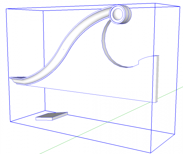
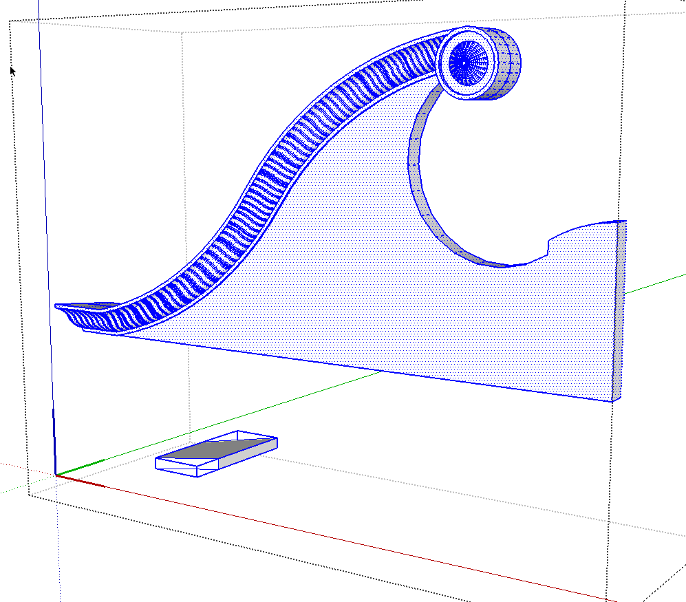
Here’s a component from a model drawn by a friend. It has a number of common issues that I see frequently.
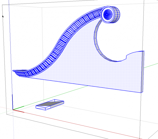
The first issue is is the component is made up of a bunch of loose geometry, selected above, and another component, in the blue box at the lower left. No matter how clean all that molding is at the top, this won’t be a Solid Component because of the other small component.
I like to think of the creation of a component as wrapping the selection of entities in a transparent wrapper. In this example we have the small component and the edges and faces of the top molding wrapped up together. If you wrap up several components in a larger component wrapper, this is referred to as a nested component. There are cases where nesting makes sense such as for drawers and frame and panel doors. If you choose to use nesting, do it in a logical manner. Make sure that each part you wish to include in the nest is a component in its own right. I often see examples such as the above where the first part is drawn and made into a component and then the next part is drawn and selected with the first component to make the next component. I have seen some examples where this process is repeated a number of times.
Although the model may look just fine, one of the big problems this incorrect nesting can cause is errors in the cutlist. The cutlist only reports the lowest level components. The lowest level components are ones that don’t contain anything but edges and faces. In the example, above, that would be the little component at the bottom. If we were expecting the bigger piece to be shown in the cutlist, we would be disappointed.
The best thing to do when modeling is to limit nesting and choose the right time to make nests after all the parts are components and in place. If you do run into something like the example, the fix is actually quite simple. Open the component for editing, select the component(s) inside and hit Edit>Cut (Ctrl+X on the PC or Command-X on Mac). then close the big component to get out of editing and hit Edit>Paste in place.
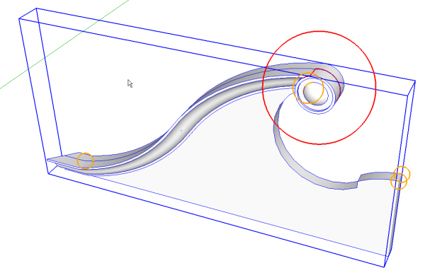
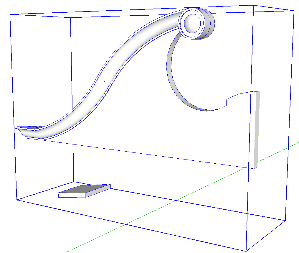
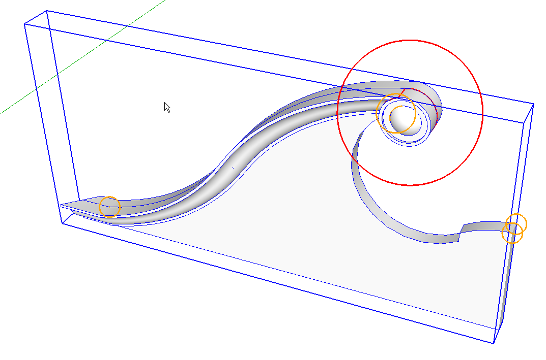
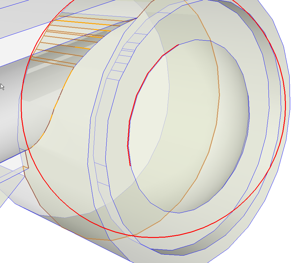
In the case of this molding, even getting that other component out didn’t make it soild. In the image above I’ve used a plugin called Solid Inspector to identify those things that are preventing this component from being solid. The red circle and lines indicates the current issue. The orange circles indicate other problem areas.
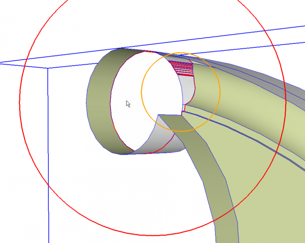
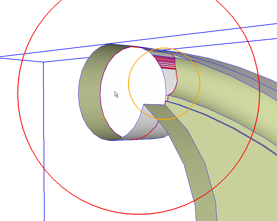
The first problem indicated is due to internal faces and edges. Here I’ve hidden the rear face of the component to make it possible to see the problem area. Deleting the edges marked in red will fix this problem.
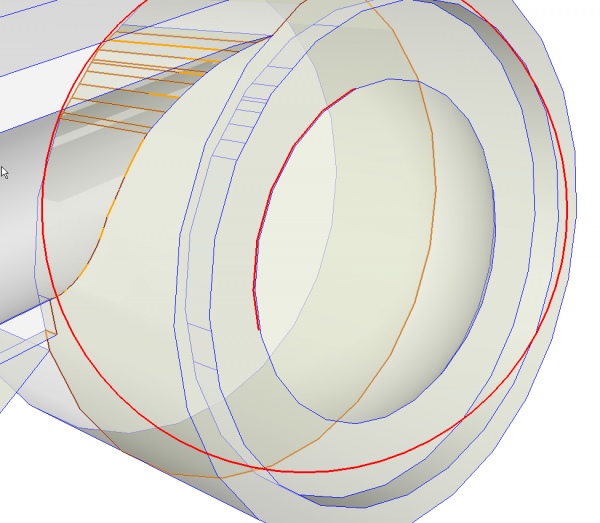
The next problem spot is some more edges inside.
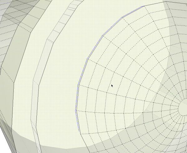
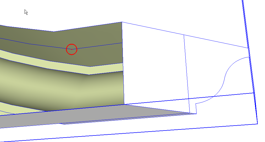
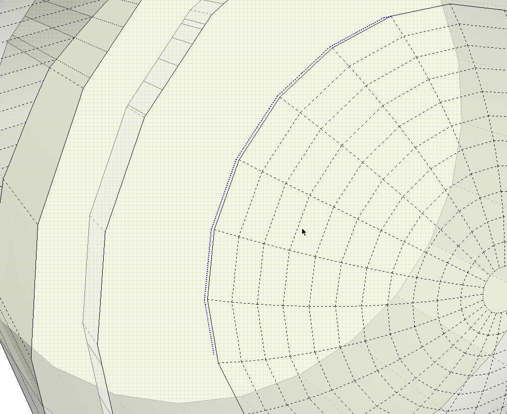
We need to turn on Hidden Geometry to see the problem edges. I’ve also switched to X-ray view for this.
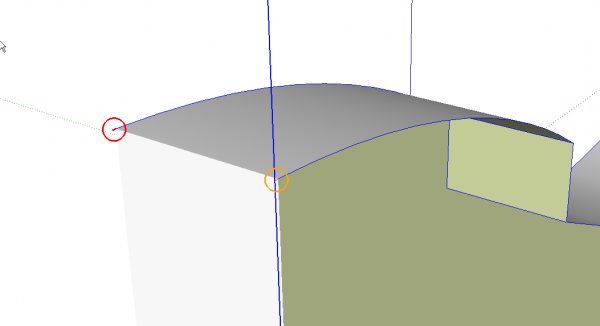
At the midline we have a pair of very short line segments sticking out.
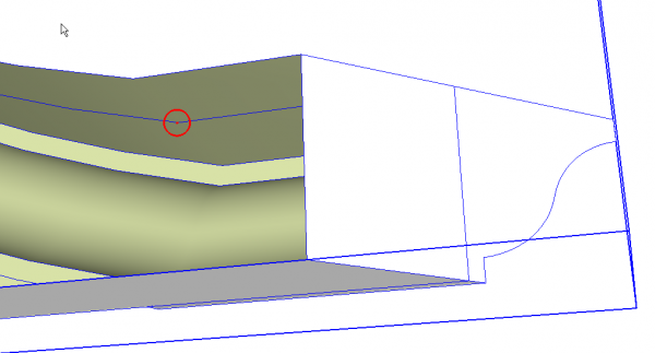
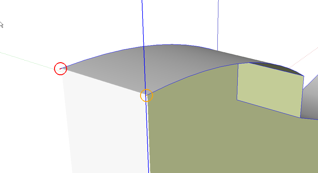
And at the other end of the molding there’s a little short line segment that was probably left after joining the arc with a straight line during the laying out of the curve.
Now, admittedly none of these problems would show in a cursory look at the completed model but, as I indicated above, they can affect information you get from the model in the form of a cutlist or other things. In addition, extra edges and faces can create problems when editing. Every edge and face contributes to the model’s file size and this can affect the your computer’s performance and the way it displays the model. These issues might result in your having to spend more time working on your model than you ought to.
If you are creating models for 3D printing, you’ll find they need to be classified as solid or the 3D printing software won’t accept the model.
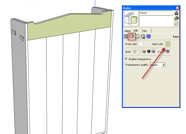
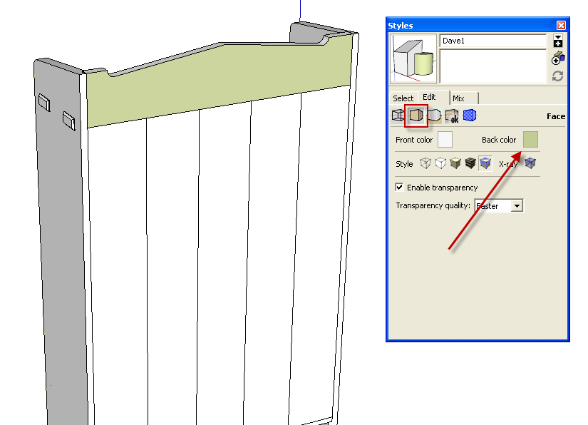
There are some other things that are just plain old good housekeeping. They might affect the way your modeling process goes or perhaps just the the appearance of your model. Face orientation is a big problem for some folks. In the xample above, the back of the top rail is shown reversed. I use a green for my back face color because it isn’t a color I would normally aply to my model and I find it easier to identify as a back face than the default bluish gray. that bluish gray can sometimes look like the front face color in shade as on the left in the above image. The green is also easier for me to see when there are little tiny holes in the model as in that knob.
You can correct the face orientation by right clicking on the reversed face(s) and then choosing ‘Reverse faces’ from the Context menu. You could also right click on a correctly oriented face and choose ‘Orient faces.’ Make it a habit of keeping up to date on this by correcting face orientation problems as they occur.
Face orientation affects tools that have a direction in what they do. The Push/Pull tool is an example of that. The results of the Push/Pull operation depend upon which side of a face the operation is performed. Also, if you want to run your model through a rendering application, you might find reversed faces cause problems. Many rendering applications won’t display back faces even if those back faces are painted with materials. Those faces wind up rendered as black. Not black with reflections but black as in there’s nothing there at all. If you discover that after you’ve let a render cook all night, you will probably be unhappy.
I’ve seen many requests for a plugin to fix reversed faces in models. There have been several plugins or maybe attempts at plugins but they don’t work with 100% accuracy because it is difficult to define exactly which way every face should be oriented. The best thing I’ve found is to draw in Monochrome face style and fix reversed faces as they occur.
There are a number of other good modeling practices that will improve the way your modeling sessions go and the accuracy of your models. Here are a few.
Drag out the radius for every circle on axis. You should see a red, green or blue radius line as you are dragging out the circle. Doing this instead of randomly orienting the radius will make it easier to get other circles aligned correctly (Dowels in holes for example) and easier to get correct dimensions.
Don’t use more edges than you need for drawing curves. A round table top probably ought to be drawn with a large number of sides. I would typically use 72 or 84 sides for something like that. I don’t know that I’ve ever need more than that, though, and I tend to work in multiples of 12 because it makes dividing the circle easy.
Conversely, for a dowel hole, you probably don’t need the default 24 sides. Maybe 12 would be sifficient. A small round over on the edges of table legs probably doesn’t need the default 12 sides, either. Three or four sides is usually plenty. Limiting the number of sides used for these small arcs helps to keep file size down and helps to prevent missing faces.
Keep your model close to the origin in the drawing space. This will help to keep you from getting the Dreaded Clipping Plane.
Purge your model of unused things periodically. You can purge unused materials from the Materials browser and unused components from the Components browser or you can purge all unused from Window>Model Info>Statistics. While you’re in the Statistics window, you might also click on Fix Problems and see what happens. If you get a list of fixed items, you’ll want to investigate your model and find out what they are.
I’m sure I’ve missed some things in this blog post. I’d be interested to know what things you find contribute to making your models clean and easily handled. Post in the comments section if you like.



Comments
Hello Dave,
I like to read about Sketchup and woodworking, but this time I couldn't resist to write something here,because "solid" is "my area" :)
I'm an author of the SuSolid (www.susolid.com) plugin and I like to see challenging models that my plugin can solve.
So,I would like to explore your original model with all the mistakes and see how much time it will takes me to resolve it.A challenge:)
Can you post your model here?
Great article! How do you change the default so the back faces are green?
David, I assume the model you're interested in seeing is the one of the molding. I'm sorry. There isn't anyway to post the model here and it isn't mine to post.
John, thank you. Changing the back face color to green is done by going to the Edit tab in the Styles dialog and choose the 'Faces' from the row of cube icons below the tabs. Click on the blue/gray square and change the color as desired. Click on the thumbnail at the top to update the style.
If you'd like to change your starting template to include the green back faces, or whatever other color you choose, follow the above steps for a new, blank model. Then click on File>Save as template, give it a name, ensure that 'Use as default' is ticked and save the file.
-Dave
Log in or create an account to post a comment.
Sign up Log in