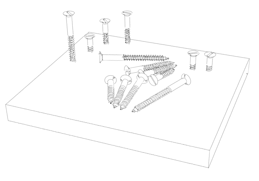
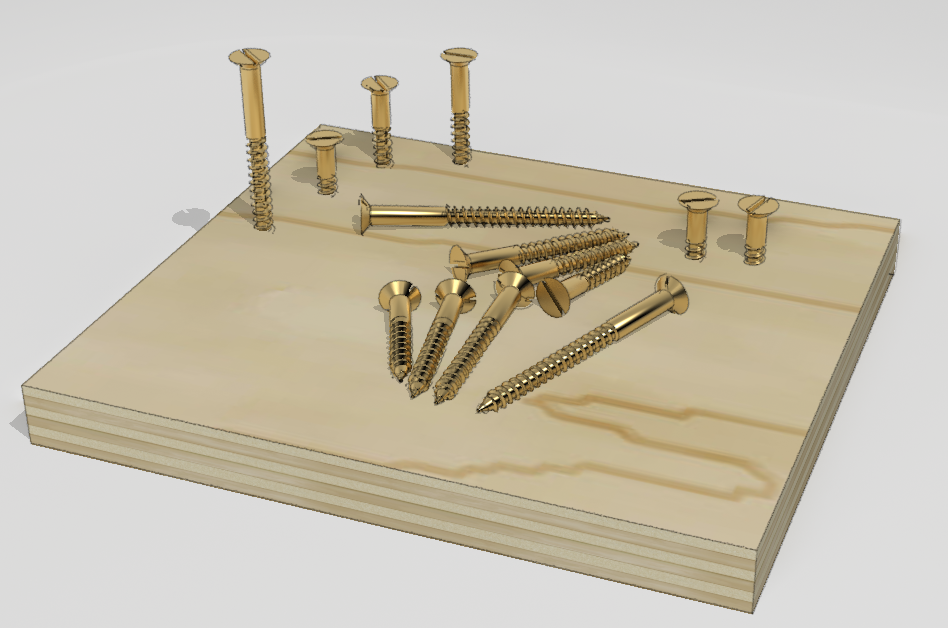
In the past I’ve written about making and saving components for future use. I’ve stressed repeatedly the use of components instead of groups and how to leverage components to save yourself work and time later. The screw components I use in project plans is a good lesson in rolling these things together. I’m not advocating that you should add screws to your models. My opinion is that details such as screws, nails dowels or other small joinery bits aren’t really all that useful in most cases and in most personal projects. I include those things in the plans I draw because I don’t know for sure who will be building the project and screw locations might not be obvious to them. For my own projects, I can deal with the screws when I get there in the real wood so I don’t add them. Either way, I hope you can find something to take away from this that you can apply to your own drawing projects.
For this blog post I’m using a couple of plugins. I start with Draw Helix and then use Curviloft.
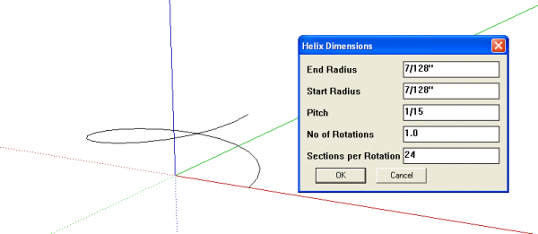
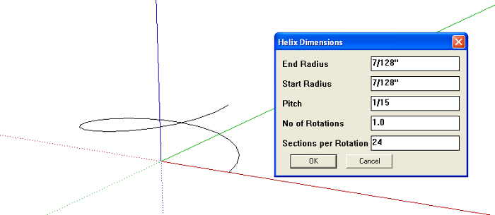
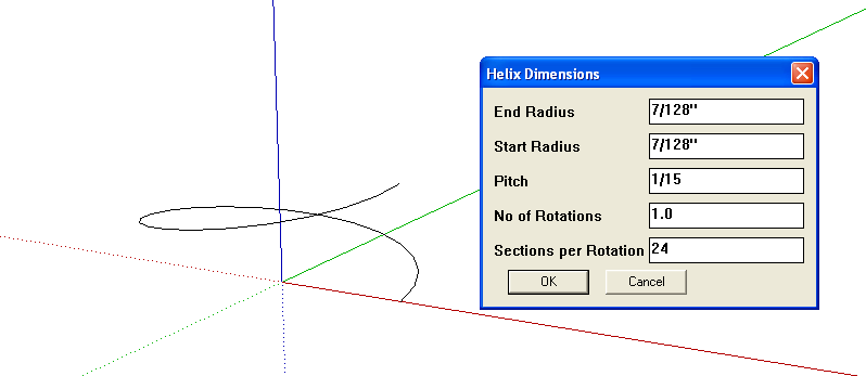
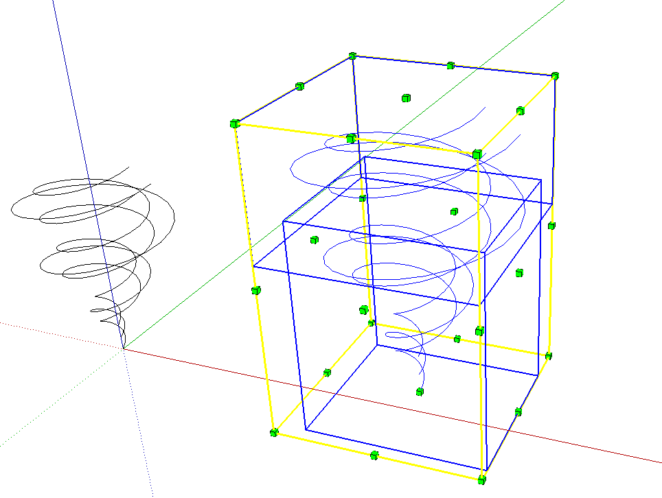
I begin with drawing a single turn helix for the major diamter of the thread. I’m working with the dimensions for a #8 wood screw. Although I’m not trying to make a totally precise model of the screw, I find it easier to work with known dimensions. After I draw the major diameter I repeat the plugin to create the minor diameter helix using the settings you see in the dialog box.
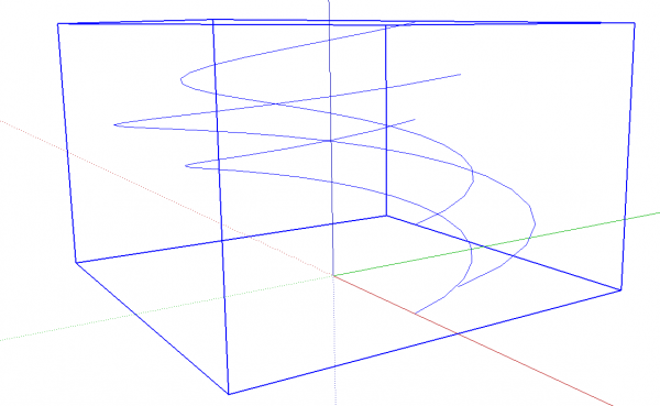
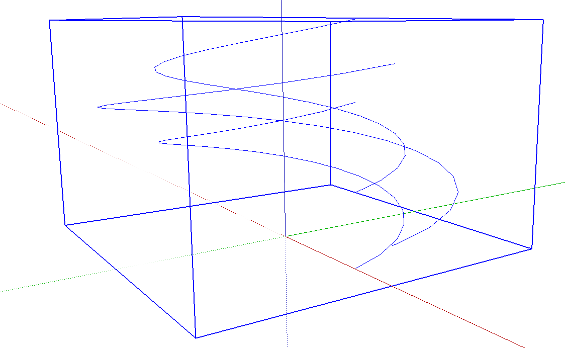
I moved the major diamter helix up 1/64th in. and made a copy of the minor diamter which I moved up 1/32 in. These helices are made as groups which I explode and combine into a single component.
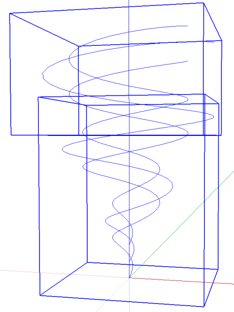
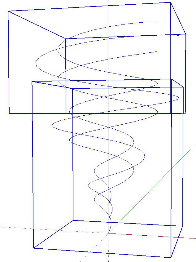
I repeated the above process except I created tapered helices by setting the start radius to 0. Again, I exploded the groups and while they’re selected, I created a component of them. At this point I have two components each consisting of three helices.
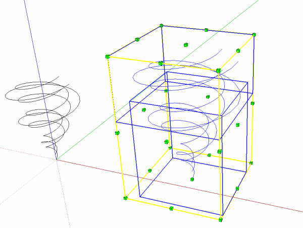
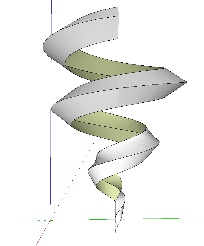
Here’s the first place where I’m going to leverage these components. SketchUp won’t fill in the tiny faces we need to make the screw threads so I make a copy of the two components and scale the copies up by a factor of 1000. Now, editing these two scaled copies will result in the originals being edited correctly, too. And, since these are components, when I’ve finished with the giant versions, I can simply discard them and go back to the original, correctly sized components. I know some folks prefer to use groups instead of components. If that’s their choice. If these were groups, though, there’d be no point in making copies of them to work on since the edits would get reflected in the originals. You would have to scale up the originals and then scale them back down when finished.
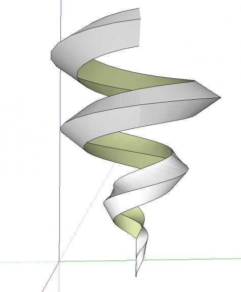
After scaling up, I opened one component at a time and drew in lines to join the helices at each end. Then I used curviloft to create the faces. See my previous blog post for more on using Curviloft. The plugin creates groups which I exploded. I also made sure the face orientation was correct. When I was finished with these two components I closed them to get out of ediit mode and then deleted the giant ones. Zoom Extents took me back to the originals.
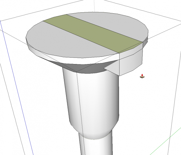
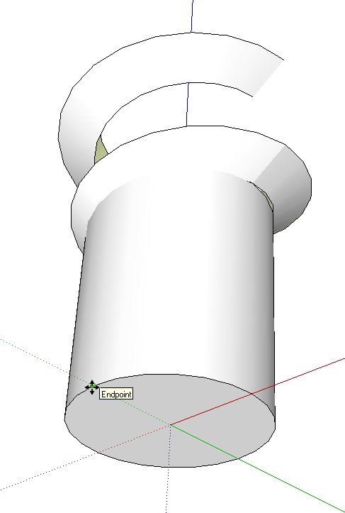
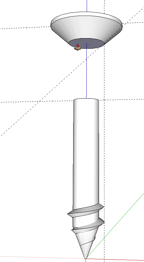
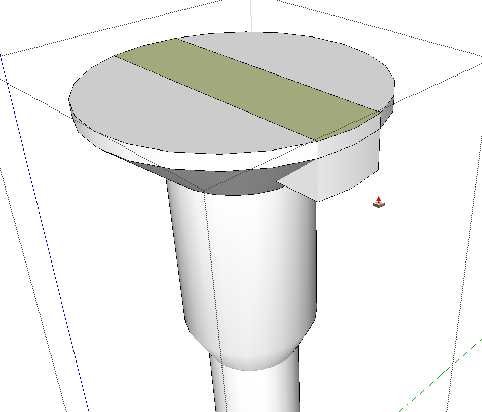
I created the body of the screw as a component separate from the threads. To cut the slot in the head, I repeated the process of copying it, scaled it up the copy and edited the large version. I just drew lines on the top face defining the edges of the slot. then I used ctrl+Push/Pull to push top face down into the head. I selected the geometry, right clicked and chose Intersect Faces>With Selection. Then I deleted the unwanted faces, closed the component and deleted the giant copy. Again, Zoom Extents takes me back down to the original.
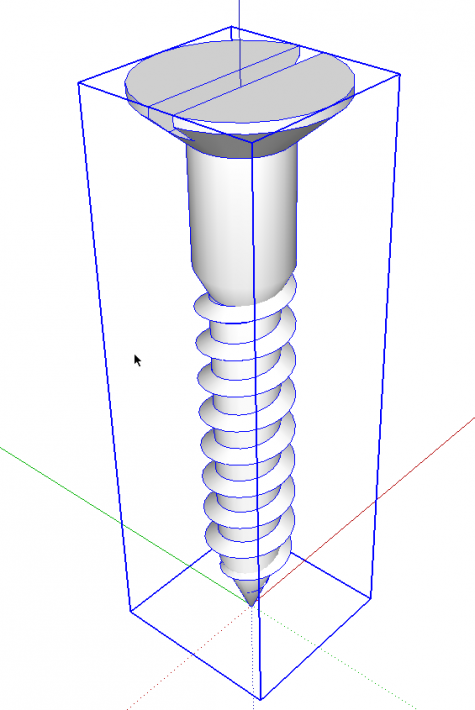
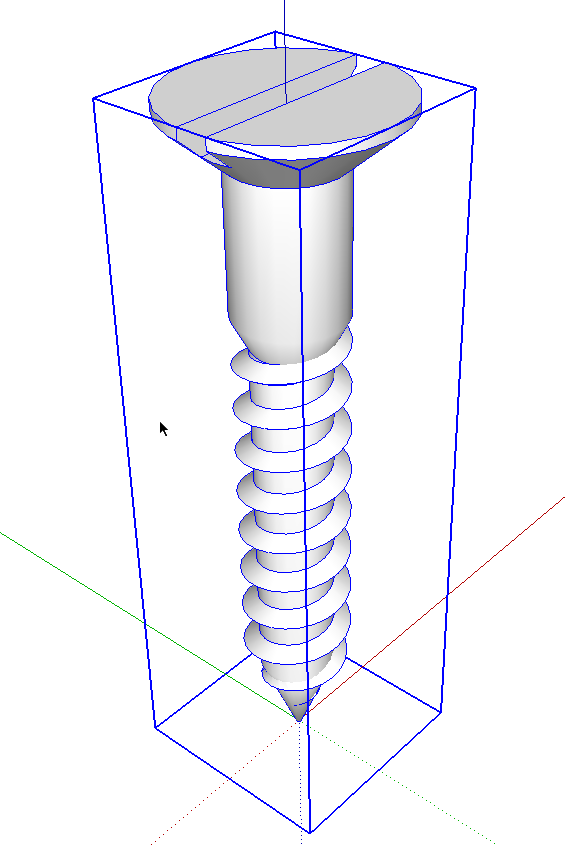
to complete the threads on the screw I only need to copy the top thread component up the screw making a linear array. I select all of the components that make up the screw and make them a component which I can save for later use.
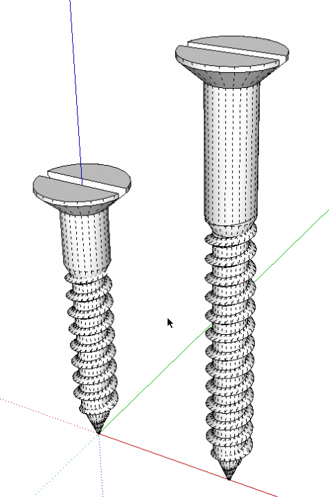
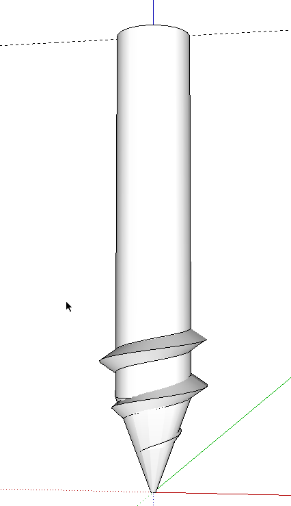
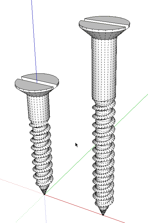
And now for the adjustable part of the screw. The original screw is on the left, above. To make the longer one, on the right, I made a copy of the original, right clicked and chose Make Unique. I then opened the new component for editing and selected the screw body component which I also made unique.
The first screw I drew as 1in. long. the copy is 1-1/2 in. long. To make it I selected just the head geometry and used the Move tool to move it up 1/2 in. Since the threads on a wood screw are typically about 2/3 the length of the screw, I moved the taper at the bottom up to 1 in. It’s easier to do this if you turn on Hidden Geometry in the View menu. Use a left to right selection box around just the taper to allow you to select that bit for moving. Make sure you move up in the blue direction to prevent deforming anything.
With the body of the screw finished, close it and select the top thread compnoent. Do not open it for editing but instead, copy up the required number of times to get the threads up to the bottom of the shank.
Close the screw component to get out of editing mode, go to Window>Entity Info and change the na,e of the component to reflect its new length. Save the component for later use and you’re all set.
When I started out with drawing the screws, I only needed a single length so that’s what I drew. In a later project I needed a screw of a different length so I edited the screw to make the new length. that took seconds instead of the three or four minutes required to make the whole screw. since then I’ve also had need of round head and oval head screws. These are number 8s but by scaling I’ve made number 12’s and number 6s. I invested a little time up front to make a halfway respectable screw in an efficient manner and saved it out for use in other projects. From then on, I’ve had little time invested in making additional screws for my hardware collection.
This same idea could be applied to many other things you might use frequently. Hinges and knobs, kitchen cabinets, doors, and so on.
Try to think about ways you can save yourself time down the road by making efficient, adjustable components up front



Comments
nice work! i'm working on something like this using a dynamic component where the thread, shaft, and head type can be set. i do this with nails as well. definitely saves a lot of time with detailed drawing areas. i also use "dumbed-down" components for wider perspective drawings to keep drawing complexity lower (then replace with detail components for details, or something like "ghost" components). i'd like to see something like this for LayOut to enable adding 2D fasteners when needed... :-)
A dynamic component would be cool for this. I've thought about making one, too but after creating non-dynamic components for the screws I need, I figured I have what I need. And of course users of the free version of sketchUp can make them this way.
The dumbed down version for wider views is also a great idea.
I guess you could make a scrapbook of hardware to insert in LayOut. I haven't done it because it's easier to accurately place screws in SketchUp once the component axis is properly located and they're properly scaled to suit the view. Still, for 2D views and to keep the SU file size down, leaving the screws for LO would be handy. It would be a handy way to show screws in place, too.
Thanks. You've got me thinking about a change to some of my workflow.
--Dave
Thanks for a great post. I'm having trouble drawing the body to match the threads I managed to create. I can't figure out how to draw the tapered part (inverted cone). Ay tips you can offer would be appreciated. I'm sure I'm issing something simple here. My mind is foggy from figuring out the threads!
Thanks,
Tony-Memphis
Tony, there's a couple of ways you could draw the body of the screw with the point. I drew a cross section of the screw with its centerline at the center of a circle. Then I used Follow Me to "turn" the screw. That's probably the easiest way. Draw from the tip of the screw up at the radius of the minor diameter of the threads, then add in the shank and the head.
You will probably need to work at a larger scale than and scale down after you make it. Then just make the body of the screw a component independent of the threads so you can adjust its length easily.
-Dave
Adjustable components are key when you are trying to achieve something that is customisable for now or for future usage. Some examples I can think of right now are boxes that are used for accessories or jewellery. The top portion acts as a lid that can be tilted or opened in order to retrieve the belongings inside. Over time, when the amount of items inside increase, then the lid can be adjusted accordingly. That is one benefit of such adjustable component I can think of as of now. I guess there are probably many more items that need such adjustable components like furniture pieces too.
Log in or create an account to post a comment.
Sign up Log in