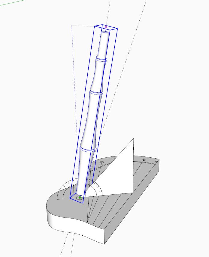
In the last session, I compiled the Windsor seat component with spindle and leg sockets. I also carved a gutter decoration separating the spindle socket platform from the front of the seat. I also traced the Sight Lines from the imported Fine Woodworking drawing, that we will need to place the Legs
We could do some sculpturing of the seat at this stage, but I usually postpone this until I have all components in place.
The video below shows how I connect the Legs at the proper angle to the seat blank. In the case of this Fine Woodworking article, Sight Lines are shown in the drawing. Often I make Windsors from photos or orthographic drawings showing the Front and Side Views. These typically do not show Sight Lines but show compound angles for the Legs – that is, an angle in the front view, and another angle in the side view. For these cases, the procedure for placing legs in SketchUp is slightly different. I may show this procedure in a later video.
Back to the Fine Woodworking article….. the leg tenons are shown tapered. This is a typical option for Windsors, however I prefer using straight tenons without tapered sockets. I also wedge the tenons at the top of the seat.
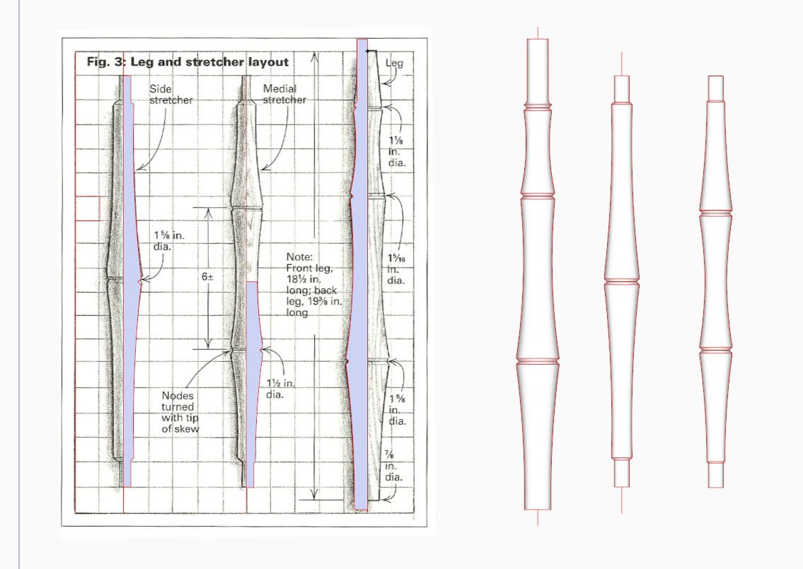
Also, Figure 3 of the article shows stretcher tenons at only 5/16-in. diameter. I think this was an error in the drawing, as stretcher tenons are normally 5/8-in. diameter.
Figure 3 also shows different lengths for the Front and Back Legs. I think the note is incorrect in that the Front Leg is shown as the shorter one. I think it works out best to use a common leg length at the 19 3/8-in. dimension. Normally, the top of the seat is at 18-in. off the floor at the front, and there is a slight tilt of the seat so that the top of seat at the rear is 1/4-in. lower.
So far in this video series, I’m showing the seat without a tilt, and on the green axis. Later I will adjust the tilt.
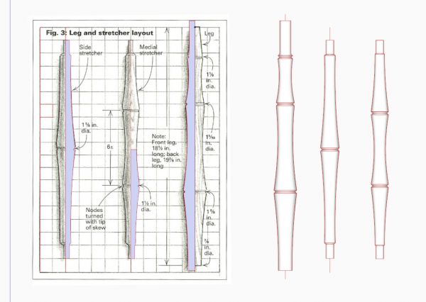
Here are the turnings for the Windsor Chair. I’ve traced over the scanned drawing from Fine Woodworking.
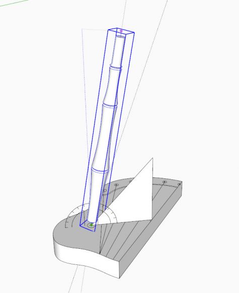
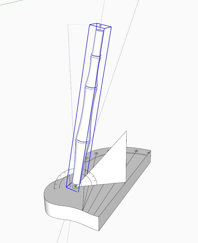
Here is a picture of rotating the leg into position using the Rotate Tool on a plane that is perpendicular to the seat and on the Sight Line.
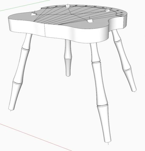
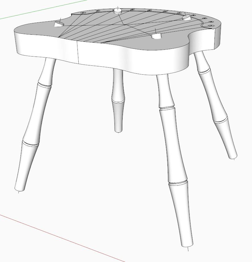
And here is the result of placing both legs and copying to create the whole seat with all four legs.
The next session will be on placing the stretchers.
Tim
http://killenwood.com




Comments
Tim,
Good series of videos. A nice complement to your e-book, the SketchUp Guide for Woodworkers.
One question: After rotating the legs and moving them down along the angled guideline, how do you ensure that the ends of the legs are in the same plane? In other words, what do you do to ensure that all four legs will touch the floor?
David Heim: Thank you for the note.
"Leveling" the chair is the last thing I do after glue-up and before finishing. I set the chair on a very flat and level floor or on the table saw. I usually want the front top of seat at 18-in. and the back of the seat at 17 3/4-in. I use a level and shims to adjust the legs for this arrangement. Then I make a marking block to scribe around the legs to show the cut-off location.
For this procedure to work properly, I make sure that the legs are long enough in the SketchUp design. In the case of this chair, I found the 18 1/2-in. length for the front leg as shown in the Fine Woodworking article to be too short. So I've used 19 3/8-in. length for all four legs.
Tim
Log in or create an account to post a comment.
Sign up Log in