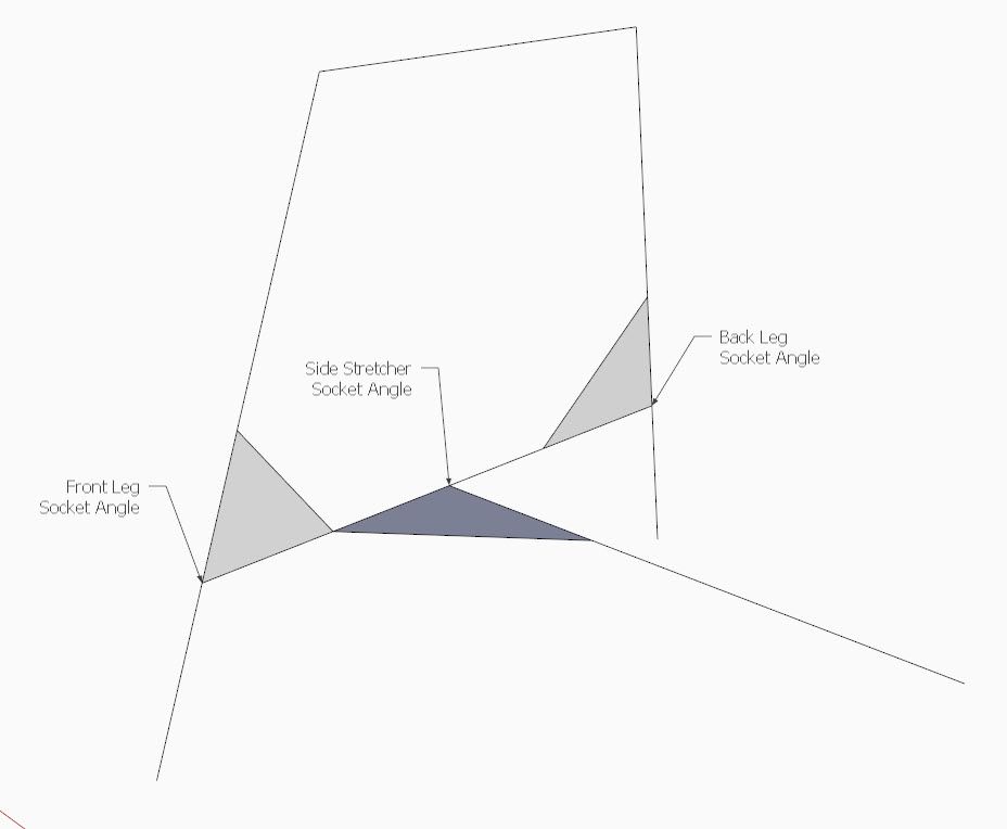
In the last episode, we completed the undercarriage of the chair with the legs and stretchers in place and connected to the seat. At this stage of design you could begin construction of the chair, although there would be some risk that spindle and bow angles may change as we model-up the upper section of the chair. If you did proceed in the shop, you would discover lack of angle values of leg sockets for Side Stretchers. Also you would be missing an angle value for the sockets in the Side Stretchers for the Medial Stretcher.
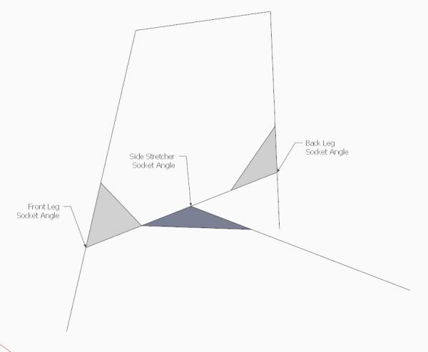
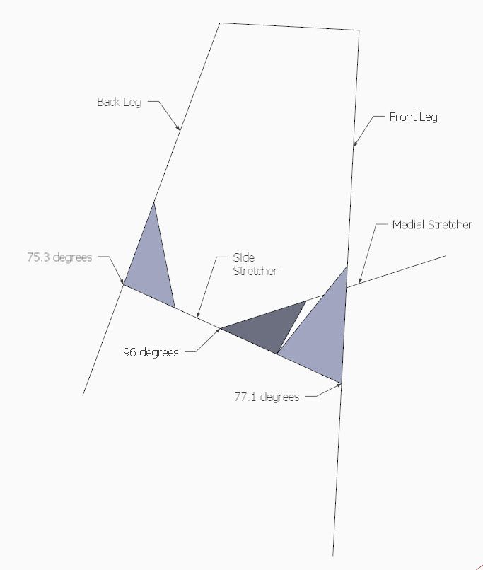
Here is an illustration of the missing information where I’m showing the connected centerlines of the Legs and Stretchers. The identified corner of the triangles indicates the socket location and the angle at which it must be drilled.
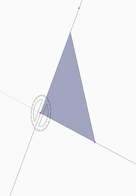
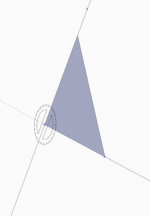
In the following video, I’ll show how I create this Centerline Diagram, and how the angles are determined in SketchUp. This screen capture shows the Protractor finding the angle between the Back Leg and the Side Stretcher.
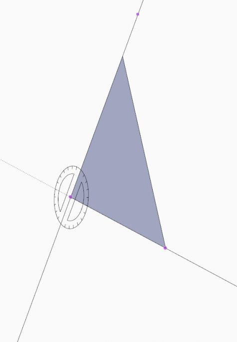
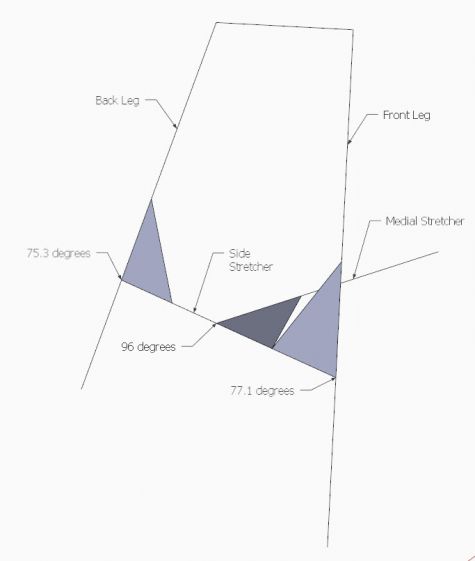
When I’m done creating a Centerline Diagram, I make it a Scene so that is part of the documentation package used in the shop.
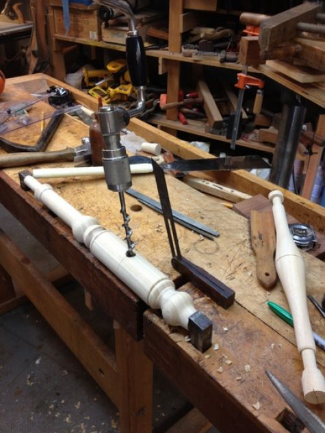
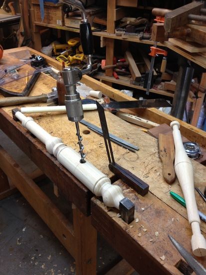
I am currently building a Low-back Windsor Arm Chair and here is the actual drilling of the leg socket for the side stretcher. I use a bevel guage to show the proper angle for the the brace and bit.
Here is the video:




Log in or create an account to post a comment.
Sign up Log in