A Trestle Table with Modern Appeal
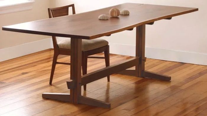
A graceful tabletop edge highlights the clean lines of this classic design with modern details.
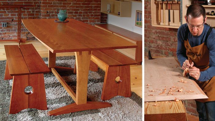
Synopsis: This trestle table combines a classic design with modern details in a way that will fit into almost any home. The base is held together with mortise-and-tenon joints and lap joints, cut before the parts are shaped. The top, with its distinctive gently curved edges, looks complex but is quite simple to make. You create it by combining two simple edge treatments, a bevel and an arc. Size: 36 in. wide by 72 in. long by 30 in. tall.
Several years ago, I wrote an article about a bench with clean, contemporary lines that I’ve made many times (“A bench that Fits Every room,” FWW #207). In the article the benches were photographed alongside one of my tables, which they often accompany. Since then, many readers have asked about the table, requesting a follow-up article on how to build it. I’m flattered, and happy to oblige.
Like the bench, the table has traditional roots with a modern feel. Its most distinctive feature is the top’s gently curved edges, which seem to vary in thickness. what’s surprising about the effect is that even though it looks complex, it’s very easy to create. I’ll show you how.
I’ll also demonstrate how to make the trestle base using a hollow-chisel mortiser, an invaluable tool. If you don’t have one, dig into the FWW archive for other mortising methods.
I also use a sliding tablesaw and shaper, but you can use a crosscut sled (or miter gauge) and router table instead. Normally, FWW wouldn’t show commercial and industrial tools like these, but the truth is when you make furniture for a living as I do, you cannot compromise on your machinery. These machines have features (like the mortiser’s X-Y table) that allow me to work more efficiently.
In terms of construction, this table is identical to the one shown in the bench article, but it is smaller. The earlier version was sized for a dining room and could fit two benches on a side; this one is the right size for a breakfast table and fits one bench per side.
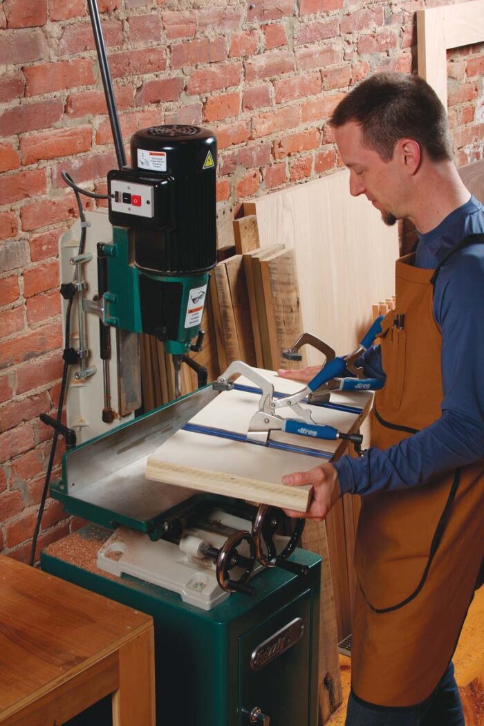 |
Add a bigger table to your mortiser. If yours has a moving table, bolt this one down. If not, it will need to slide. With its hold-down clamps, the auxiliary table allows you to mortise oversize parts. |
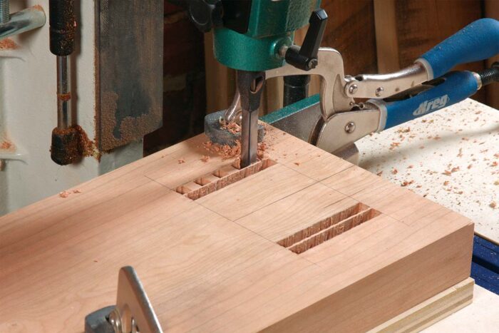 |
Outside rows first. Use a bit that’s less than half the mortise’s width. Because these are through-mortises, you can finish with a single cut at each end to remove the waste between rows. Use a backer board so that you don’t ruin your auxiliary table. |
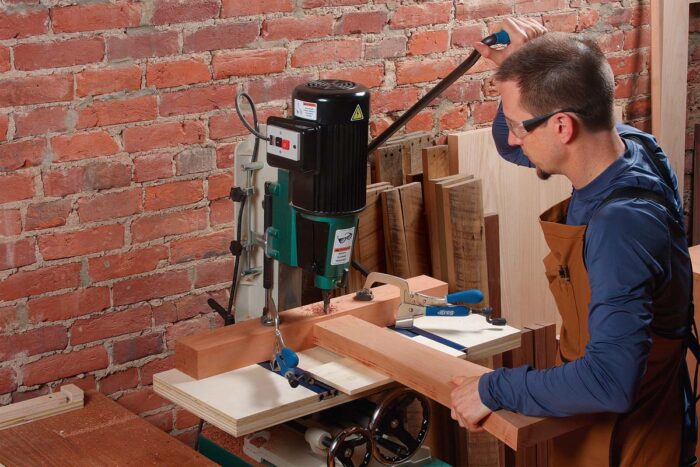 |
Different deal for the stretcher mortise. This one goes partway through the post tenon, so you need the post and foot to be dry-fit when cutting it. |
The Base Is A Lesson In Big Mortises
Except for the stretcher, every part of the base has a curve on it. If you shape these parts first, you’ll lose the straight and square edges needed to cut the joinery. So cut the joints first.
Start with the mortises, which present a few problems. First, they are all at least 7⁄8 in. wide. Second, the posts are too wide to fit between a mortiser’s fence and clamp. The solution to the first problem is to use a narrow bit (5/16 in. or 3/8 in.) and cut along the outside walls first, then go back and remove the waste in the middle. For larger parts, take off your mortiser’s clamp and replace it with a large plywood auxiliary table. Mine has two T-tracks, so I can use hold-down clamps to secure parts for mortising.
If your mortiser doesn’t have a sliding table, then don’t bolt the auxiliary fence to the mortiser’s table. Instead, leave it unclamped so that you can move it between cuts and adjust the fence. There is one mortise that you can’t cut now. It’s on the inside edge of the foot and goes partway through the tenon on the bottom of the post. You’ll cut it after dry-fitting the tenon into the foot.
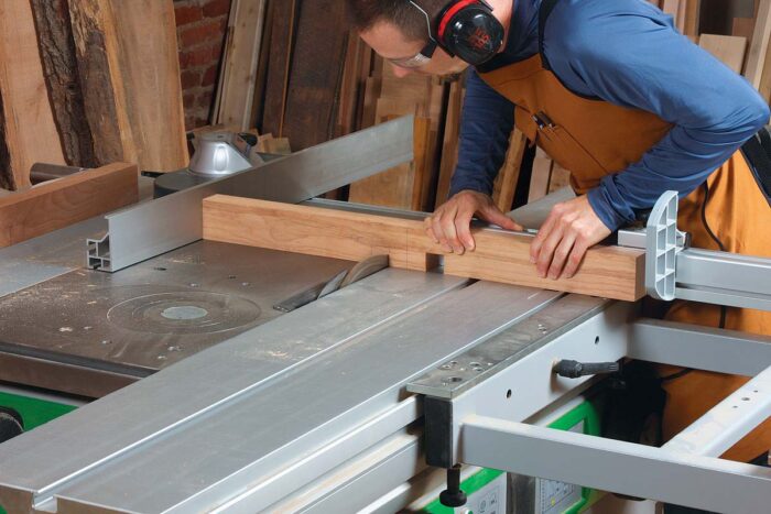
Compared to the mortises, the tenons are a breeze. I cut them with a dado set and miter gauge (with auxiliary fence) on my tablesaw. Because this is not a through-cut, you can use your rip fence as a stop to control the tenon’s length. All of the wide cheeks can be cut with a single setup. Then, after a quick blade-height adjustment, all of the narrow edge cheeks can be cut. After fitting the tenons, dry-fit the post into the foot and cut that last mortise.
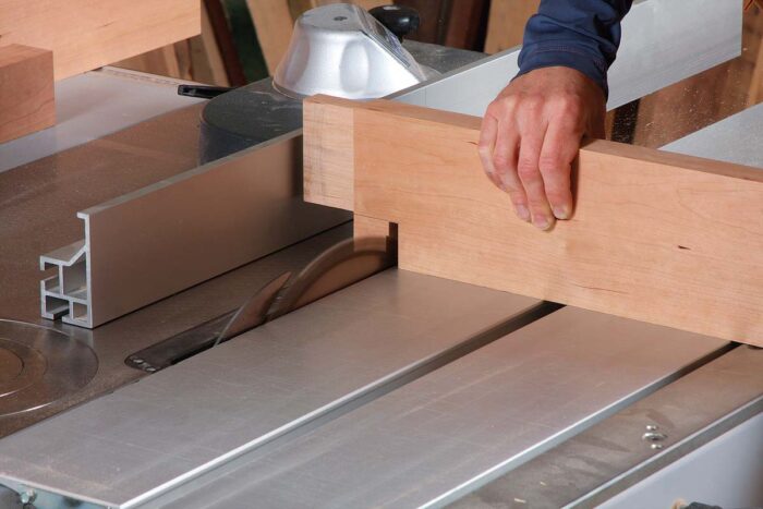
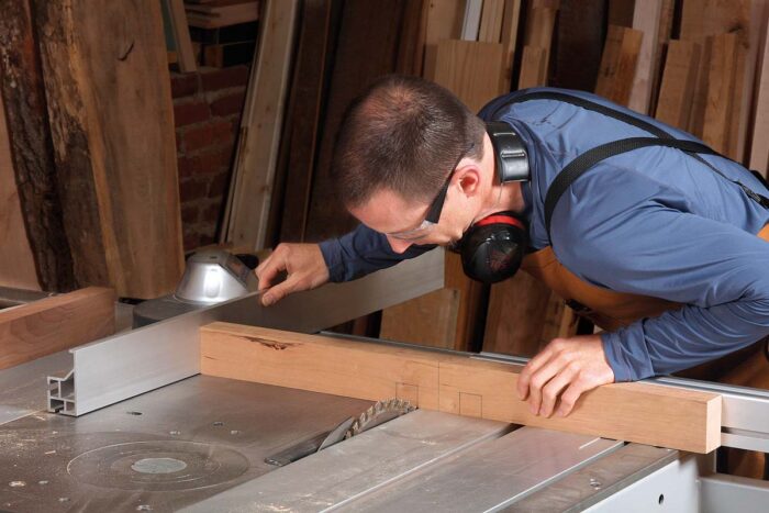
Next up are the lap joints that attach the support braces to the rails. Cut the notches on the rails at the tablesaw. These are onesided notches; the second side is created by the post when the joint is assembled. Dry-assemble the posts and rails and slide the braces into the notches. Use a sharp pencil to lay out the notches on the braces, and then cut them at the tablesaw.
 |
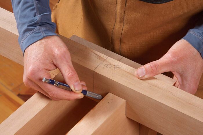 |
| One stop for the notch in the rail. Use the rip fence as a stop to control the notch’s width. Cut the shoulder first, and then remove the waste with a series of cuts. | Mark the braces. After dry-fitting the rails between the posts, set the brace in the notches, aligning its centerline with the post’s. Mark the shoulders of both notches with a fine pencil as shown. Then turn the brace over to mark the notches’ depth. |
 |
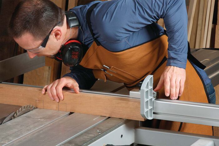 |
| Two stops needed for the braces. The rip fence locates the brace for the inside shoulder (left photo), and a stop block locates it for the outside shoulder (right). Then just flip the workpiece to cut the second notch. |
 |
Nibble out the waste. Cut the two shoulders first. Again, you can remove the waste with a series of cuts. |
Shape The Parts Before Assembly
After all the joinery has been cut, start cutting the curves. For the posts, rails, and support braces, I use a template to lay out the curve. I rough out the part on the bandsaw, and rout it flush to the template. I bevel the ends of the feet and support braces with a chopsaw followed by a block plane. But the feet are too thick to rout in a single pass, so I rough out the curves at the bandsaw and use a spokeshave to clean up the cut. I cut the tapers on the top edges of the feet at the bandsaw, too, cleaning up with a jack plane.
At this point, drill holes in the support braces for the screws that attach the top to the base and the braces to the rails. To accommodate the top’s seasonal movement, slot the holes at both ends of the braces. I overlap three Forstner bit holes to create the slotted counterbore and three brad-point bit holes to make the slotted clearance hole. Use a small file to clean up the slots Prepare all of the parts for finishing, sanding through P320-grit and easing the edges. Now glue up the base. Start by gluing the post into the foot. After the glue is dry, glue the stretcher and rails between the posts. Finally, glue the braces to the rails, and drive the screws into the joint.
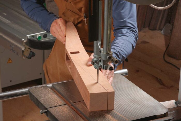 |
Shape the foot at the bandsaw. Cut the curve on the bottom and the tapers on the top. |
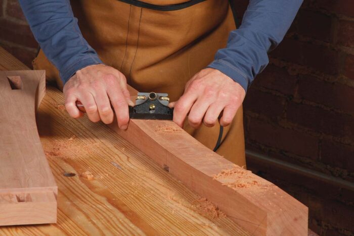 |
Clean up with hand tools. A spokeshave or card scraper works great on the curved bottom. Use a handplane on the tapers. |
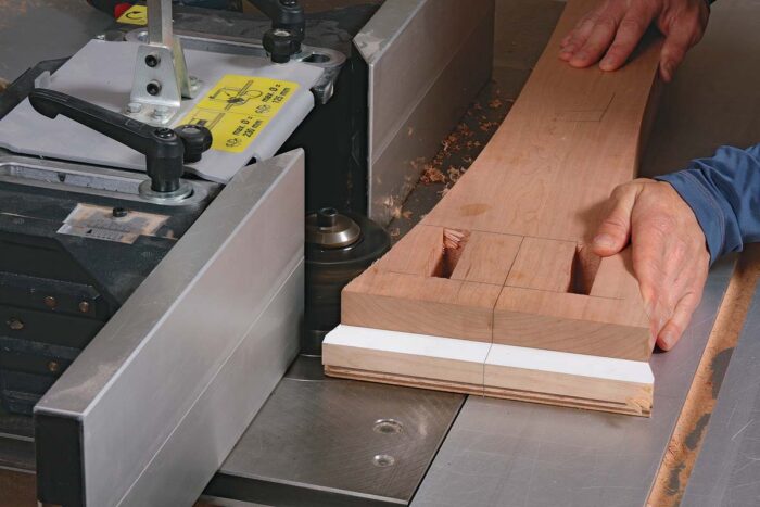 |
Flush-rout the posts. After roughing out the curves at the bandsaw, screw the post to a post template. Chaffin uses a shaper for the job, but a router table and a bearing-guided bit work, too. |
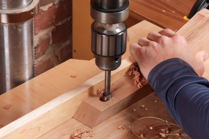 |
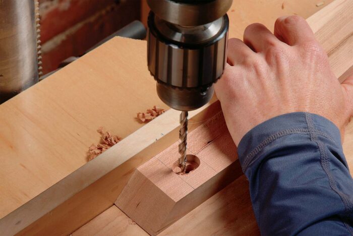 |
| Drill slotted holes for screws. The screws attach the top to the base. Start with the counterbore, slightly overlapping three holes (left). Then drill the clearance hole the same way (right). |
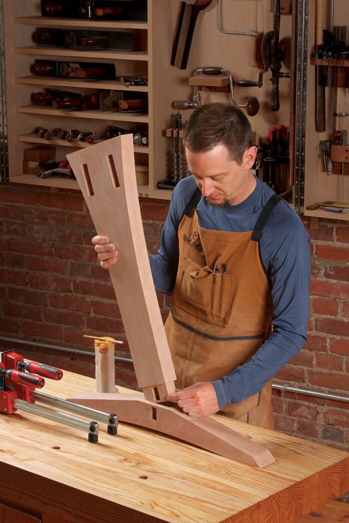 |
Posts first. To minimize the chance that glue will get into the stretcher mortise, don’t put glue on the tenon. Brush it on all four walls of the mortise instead. After inserting the post, check the stretcher mortise for glue. Do both posts, and let them dry. |
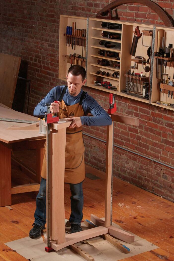 |
Add the rails and stretcher. Raise the bottom post off the floor to create clearance for clamps. Again, let the assembly dry before moving on. |
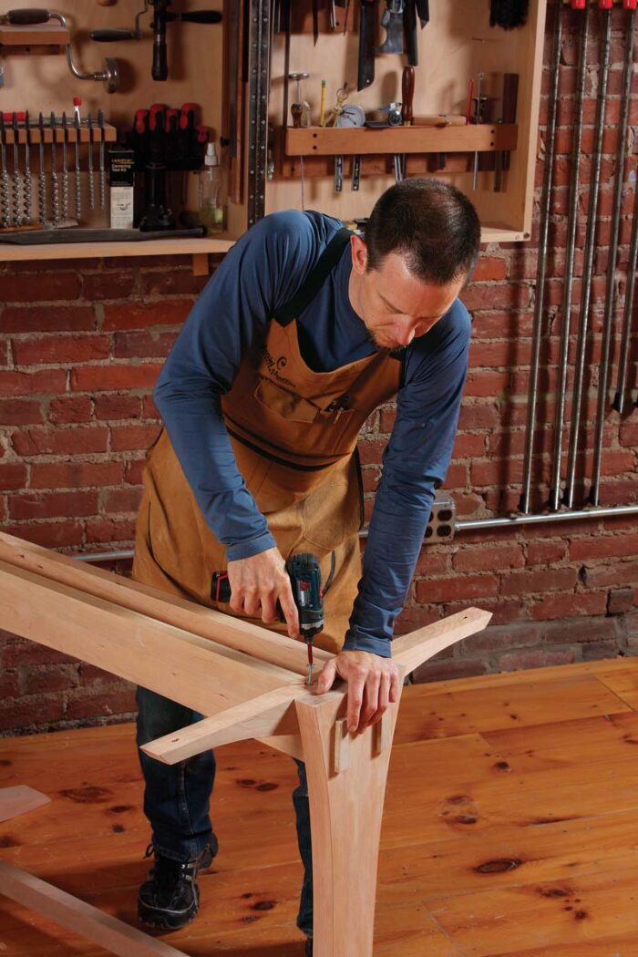 |
Glue and screw the braces. There is no easy way to clamp the braces. Screws hold them in place while the glue is drying and reinforce the joint after it has dried. |
Edge Profiles On The Top
With the base assembled, turn your attention to the top. After gluing up the boards to make it, the top should be 361⁄2 in. wide and a few inches too long. To get the side profile correct, you must first cut the top to length. The ends are beveled, and it’s easiest to cut the top to length and bevel the ends at the same time. The top is too big to do this on a tablesaw, so use a circular saw and straightedge. Tilt the saw’s blade to 30° and cut one end. Move to the other end of the top and cut it to final length. clean the bevels with a block plane, and sand them to p320-grit.
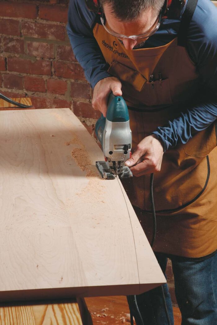
The edge profile on the sides is created with a two-step process. You’ll bevel the straight edge first and then cut a gentle arc into it. because it’s a 64° bevel, you can’t cut it completely with the circular saw, so cut a 45° bevel along the edge, and then use a jack plane to remove the remaining material. Next, lay out the arc with a long, 1⁄4-in.-thick batten. At the centerpoint of the table, the arc should pass through a point 1⁄4 in. from the edge. rough out the arc with a jigsaw, with the blade set at 90°. Use a block plane to smooth the cut and work down to the layout line. Sand the edge and the rest of the top, too.
The table is now ready for a finish. I use Tried and True varnish oil: three coats for the base and five for the top. Apply very thin coats, allowing them to dry for an hour before wiping off any excess. Then, let each coat dry for one to three days. After the first coat has dried, work the surface with 0000 steel wool. replace the steel wool with a cotton cloth, buffing between the remaining coats.
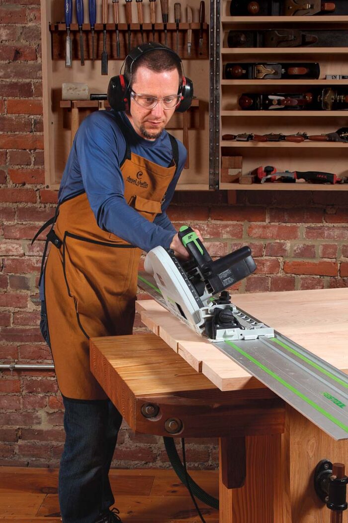 |
Bevel table ends first. One cut does it. Tilt the saw to 30° and try not to wobble. |
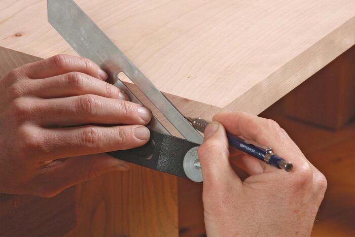 |
Bevel the table sides in two steps. Lay out the bevel. Set your bevel gauge to 60°. When you lay it on the angled end grain, it creates a bevel that’s 64° to the top. |
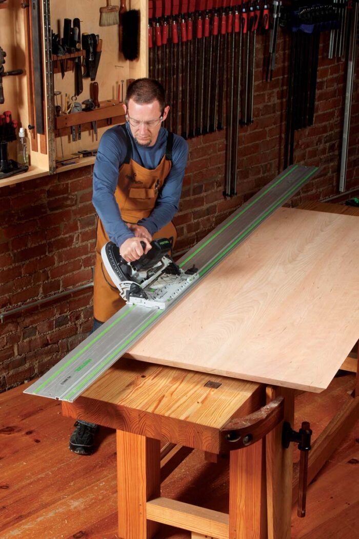 |
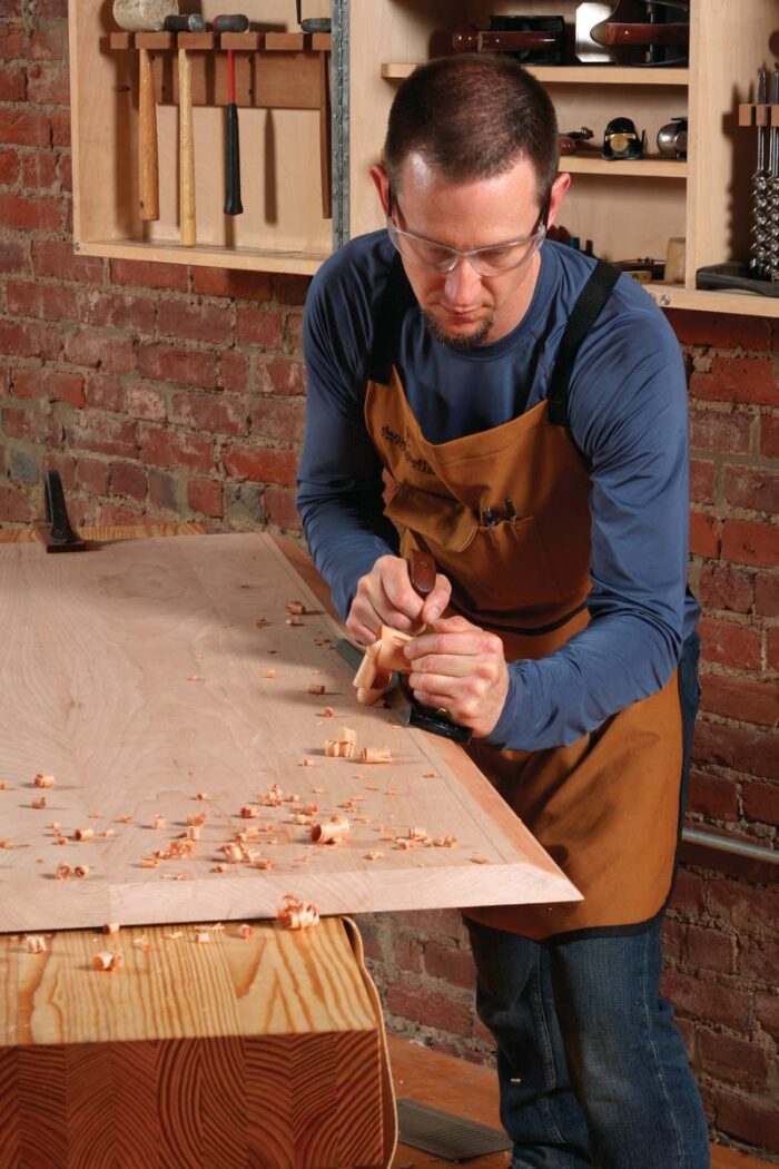 |
| Two tools do the job. Start with a circular saw (or tablesaw) tilted to 45° (left). Then use a jack plane or jointer plane to complete the bevel, working down to your layout lines (right). |
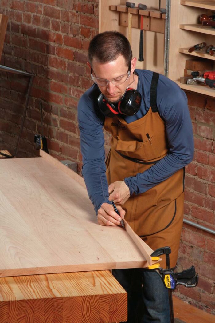 |
Now the curve. Use a batten to lay out the curve. At the ends of the board, the arc aligns with the inside edge of the bevel. In the middle, it touches the outside edge of the top. |
 |
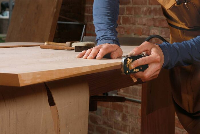 |
| Cut the curve and clean it up. Use a jigsaw with the blade set at 90° (left). Because jigsaws can create severe tearout, cut at least 1⁄16 in. away from the layout line. Clean up the sawn edge with a block plane (right). |
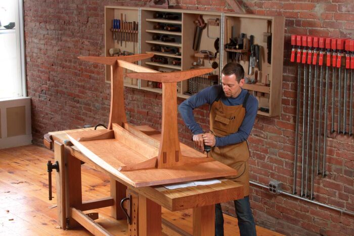 |
Attach the top. The holes at both ends of the brace are elongated to allow for seasonal movement. The one in the center is not. Chaffin uses 1-1⁄4-in.-long FastCap PowerHead screws. |
Download the plans for this table from the Digital Plans Library. Plus, browse 100+ other plans available for members only.
For the full article, download the PDF below:
Fine Woodworking Recommended Products

Drafting Tools

Sketchup Class


Log in or create an account to post a comment.
Sign up Log in