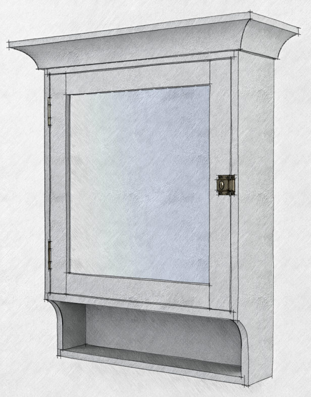
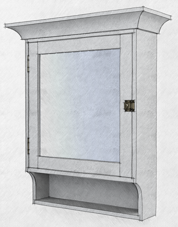
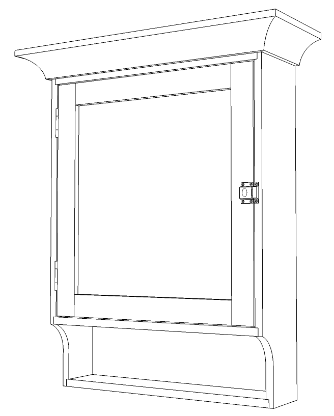
Recently I drew the SketchUp model for the plan for Mario Rodriguez’s Vanity Cabinet. Drawing the crown molding was an interesting excercise. I had few dimensions to work with and at first it seemed as if there wasn’t enough information to draw it but by using some guidelines to layout what I did know, I was able to fill in the rest. Here’s how I approached it.
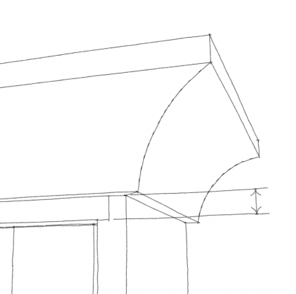
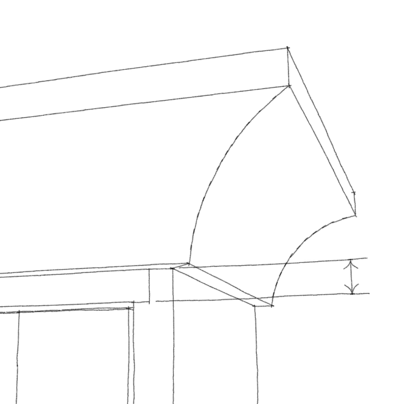
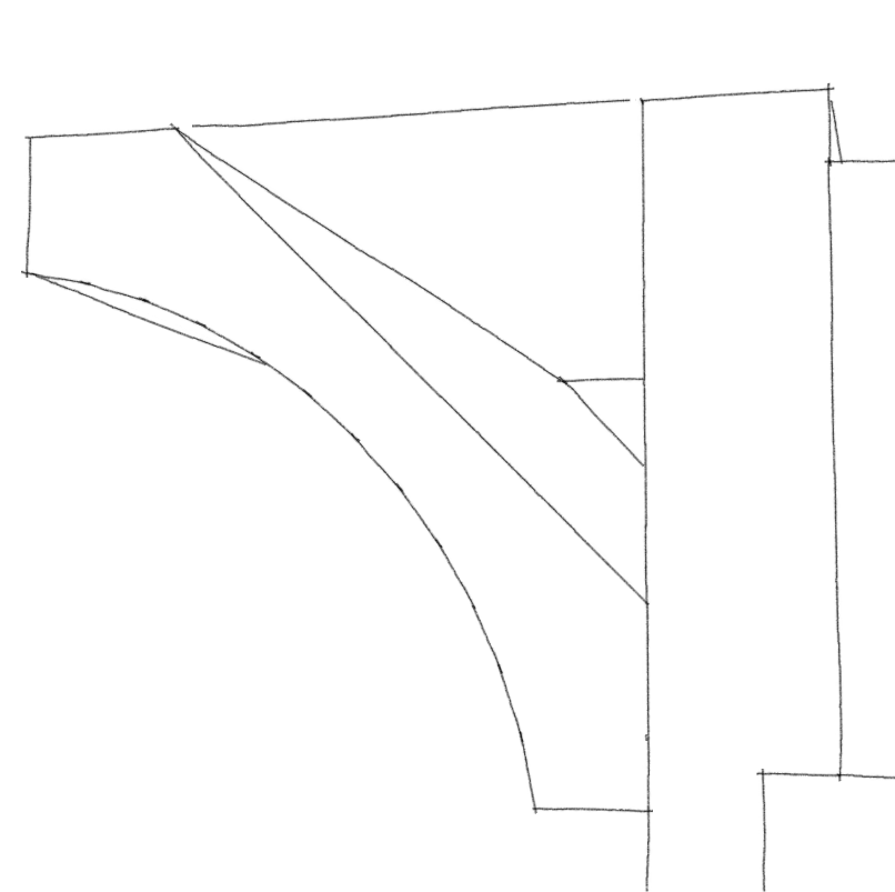
I knew the width of the horizontal srface at the bottom of the molding, the width of the vertical surface at the top and the reveal of the case top below the molding.
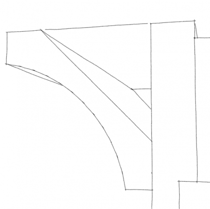
I also knew the overall thickness of the molding and the thickness at the apex of the cove. The bevel angle was shown at 45°. Finally, I knew that the top of the molding is flush with the top of the case sides.
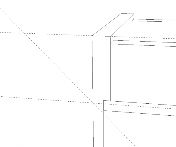
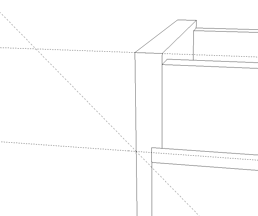
I started drawing the molding profile at the back of the case. Drawing it in situ makes getting it drawn and placed accurately very easy. I set out a couple of guidelines to define the upper and lower limits of the molding. then I set out a guideline at 45° as shown, above.
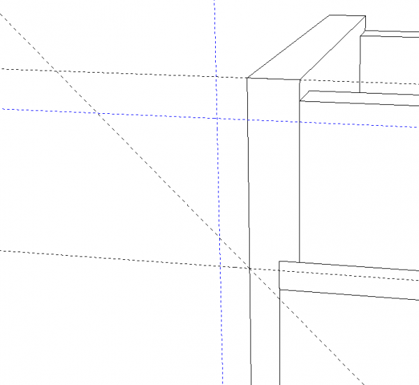
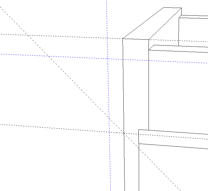
Next I added the guidelines shown in blue, above. These define the widths of the horizontal and vertical faces on the molding.
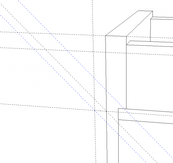
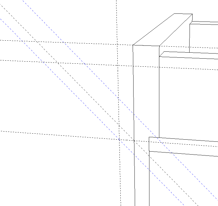
Next, I set out guidelines parallel to the diagonal; one through the intersecting guidelines at the bottom corner and another up from that to define the overall thickness of the molding. To be honest, you could omit the first diagonal guideline and just put one in at the intersection, the lower blue one, above.
I traced the outline of the molding without the cove and deleted the guides.
A note about deleting guides: Make it a habit of cleaning up the guidelines in your model when you’re finished with them. They can add a lot of clutter and confusion to your workspace if you leave them. To get rid of them, go to the Edit menu and choose Delete Guides. This is much faster and easier than deleting them with the Eraser. I set up a keyboard shortcut for Edit>Delete Guides.
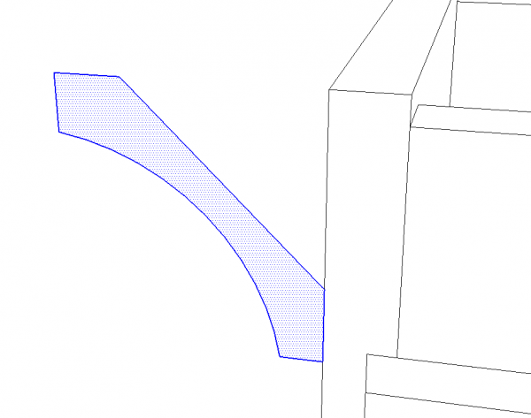
I used the Arc tool to put in the cove. A little in-the-head match told me what the bulge distance was. then the straight edge across the cove was erased. You could skip drawing that line that gets deleted but by putting it in, you get a face on which to draw the arc. That’ll make it easier to get the arc on plane.
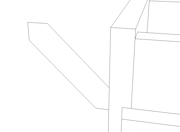
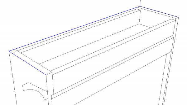
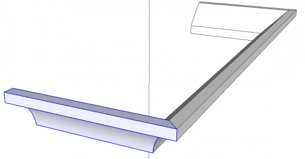
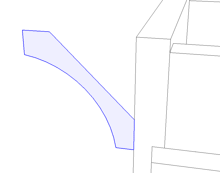
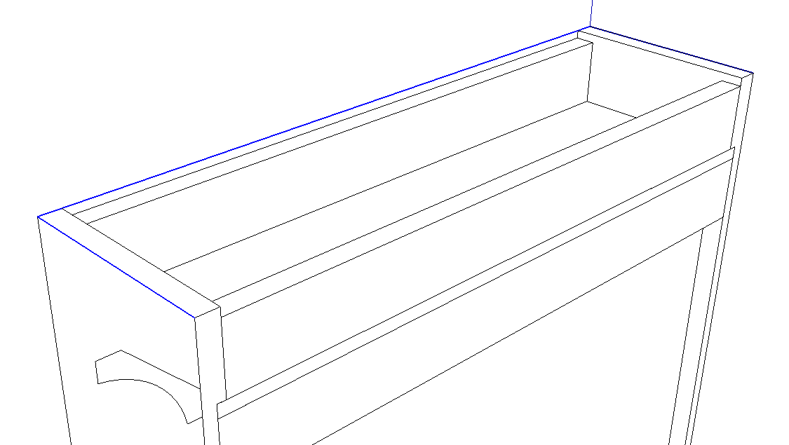
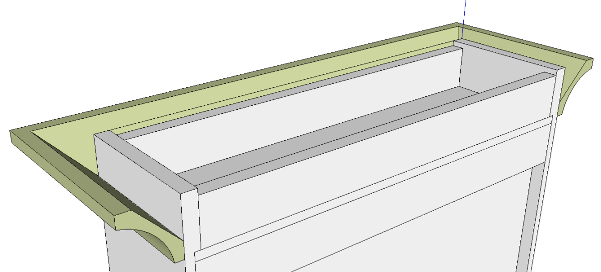
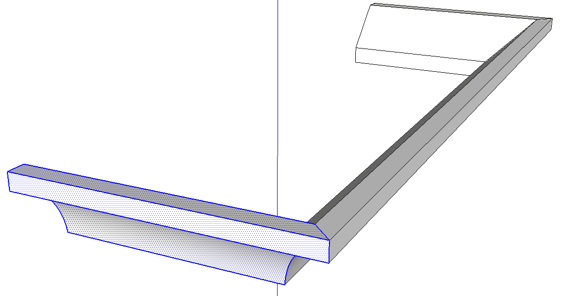
Now we’ll use Follow Me to create the molding from the profile. I drew a path for Follow Me using the Line tool. In blue, above. with the path selected, get the follow Me tool and click on the profile.
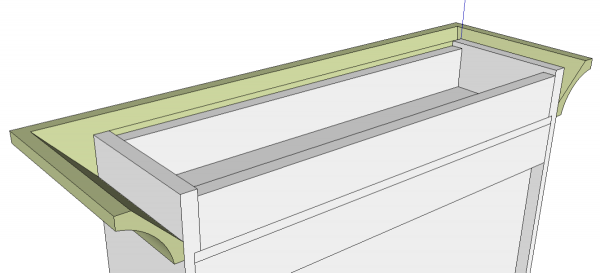
It isn’t unusal to end up with reversed faces as I did here. If you work in Monochrome face style, you’ll be able to identify the reversed faces and correct them as they occur. In the case simply select all of the geometry of the molding, right click on it and choose Reverse Faces.
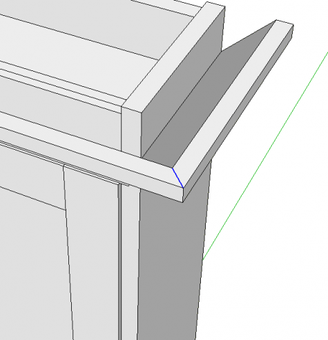
For this model I needed to show an exploded view including the parts of the molding so I divided it into separate components at the miter joints. Follow Me doesn’t put in miter lines when the faces are cop[lanar so you have to draw them in on the top and bottom horizontal faces.
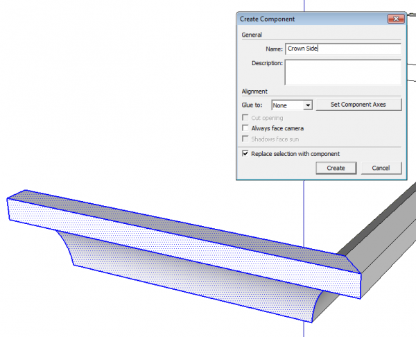
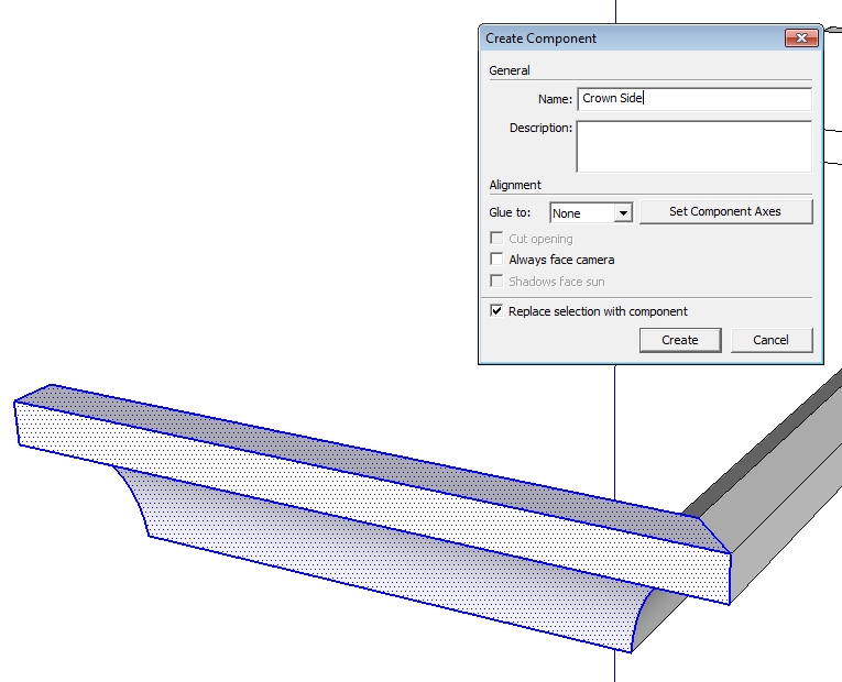
Drag a left to right selection box around the side molding to select only that geometry. Hit G to Create a Component.
Give it a name and tick the box for ‘Replace selection with component.’ Typically, when you make a component, you select all of the attached geometry. When you do, the Replace box will automatically be checked. If there’s attached but unselected geometry as in my example, above, the box will need to be manually selected.
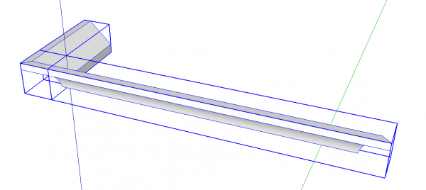
Delete the opposite side molding, make the front piece a component…
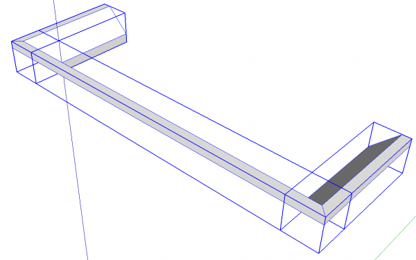
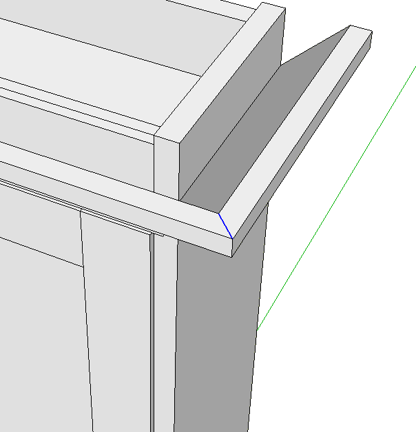
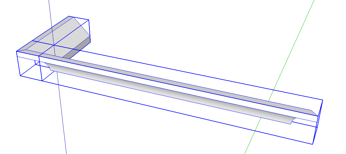
…copy the side component to the opposite end and use Flip Along to flip the copy. Since the front of the cabinet should be along the red axis and the axes of the side component are aligned with the model axes, the flip direction for this would be ‘Along component’s red.’
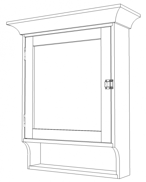
And there you have it.
Of course this process isn’t limited to crown moldings. The Follow Me and splitting process can be used for all sorts of things. Picture frames, base moldings, mitered door frames and so on.



Comments
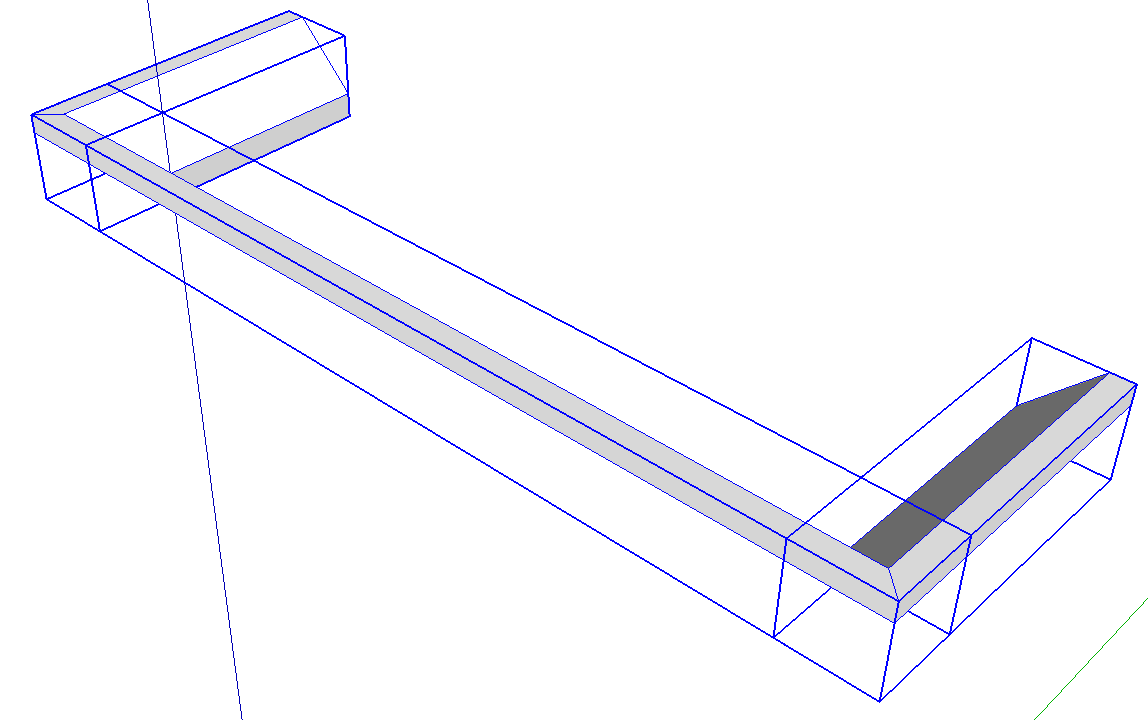
This is a great instructable for a common procedure. One thing that I have found in doing this with moldings is that you need to go back and align the component axis for these molding parts so that when running "Cutlist" you end up with dimensions that relate to actual boards. If one stopped where you left off, Cutlist would return either a component that doesn't fit on specified stock or would build up, for example, a 3x3 out of multiple 3/4 thick boards. I would align the blue axis with the back diagonal face of the molding.
Thank you.
You made a good point about changing the component axes to align with the component so the bounding box fits tightly to the geometry. I did that when I was creating the model for the plan specifically to get the cut list to report the correct dimensions although I didn't show it here.
Another reason for doing that is it can make the proper application of textures easier.
-Dave
Log in or create an account to post a comment.
Sign up Log in