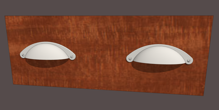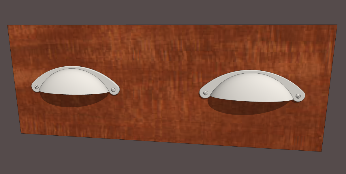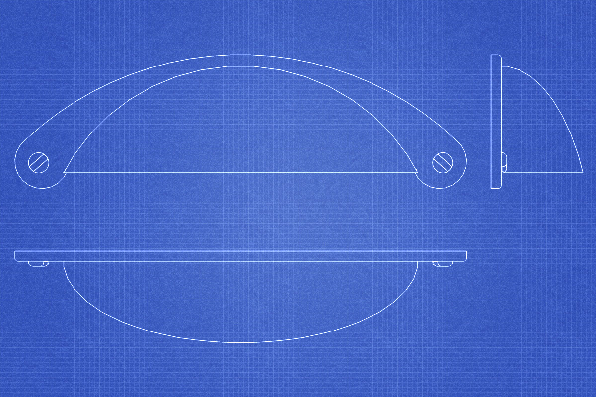
I was asked about a method for drawing a bin pull type of of drawer pull. A long time ago I did a tutorial showing how to do that but that one seems to have evaporated into the ether so here we go again. Most of the process is done with the native tools but I did employ a few plugins. The first one is Point at Center which is part of the Ruby Script Examples set which you can get from the Extension Warehouse either directly or through the Window menu if you have SketchUp 2013 or later. the next plugin is Weld and the final one is Round Corner.
None of this is very difficult but it does require doing some thing in the right order and a couple of little tricks which I’ve shown before because I use them frequently when drawing smaller objects. The first trick involves drawing only half of the pull. Due to the symmetry of the model, this saves us some work. The other trick leverages one of the benefits of using components to overcome SketchUp’s disinclination to make tiny faces. Take a look and see if there’s anything to glean out of the video that will help you in your modeling endeavors.
Remember, after you’ve made the pull component, save it to your favorite library so you can easily use it on future projects.


Comments
Dave
With regard to your general approach of only drawing half an object , then copying , flipping the copy and joining it to the other half , I notice there is still a line at the joint which you hide .
Do the two halfs still form one object/ component as far as the computer /outliner is concerned ?
Thanks for tutorial . I personally find the videos extremely helpful , the points you make seem to stay longer in the mind .
There is still a line at the seam between the two components but the edges is hidden so it doesn't show. I think I might have neglected to hide the edge on that lip at the bottom of the dome but that was just an oversight on my part.
In the Outliner the pull would show something like this:
-
----
----
----
----
If you were to include that pull in a cutlist, it would appear as two of each component; the Back plate and Dome. By splitting the parts in half the file size can be kept smaller but if you prefer having the pull as a single component, it is easy to do. If you made the pull exactly as I did, all you would need to do is open the Bin Pull component for editing, select the four components inside and explode them. If you intended to make it a single component from the beginning, you could skip making the dome and back plate components in the first place and just copy and flip the geometry instead.
I find making sub-components and nesting them useful for hardware in many cases. For example, I could easily use the same dome with a different back plate. I do a similar thing for screws and other threaded hardware. I make a single turn of the thread as a component and copy it in a linear array. Then I can quickly and easily create a new length by adding or removing turns. I've done the same sort of thing for a continuous hinge so making the hinge any length is trivial. You can see a blog post about that here: https://www.finewoodworking.com/item/25321/components-make-unique-a-simple-piano-hinge
I'm glad the video was helpful.
-Dave
That's weird. I wonder where the text went for my illustration of the Outliner went. I'll try again.
The Outliner would look something like this:
-Bin Pull
----Back plate
----Back plate
----Dome
----Dome
Sorry about that.
Dave
Thanks for the response & showing the effect of your method in the Outliner .
You have used a bin pull to illustrate the method , but if it was a say piece of furniture eg. a chest of drawers , where the back plate was the frame and the dome was a drawer , are you saying that if one intended using a program like Cutlist
for scheduling out materials , you can't draw half an item , copy it , flip it and join it to the other half as you have illustrated because the frame and the drawer are both in 2 halves in Sketchup ? .
Yes. that's pretty much exactly right. The cutlist shows the lowest level components so if you split a drawer front in half as I did with the pull, the cutlist would report two drawer front halves instead of a single drawer front.
You could draw half of the drawer front and copy and flip that geometry to make the opposite half if you wanted. I guess I don't do that for simple things like drawer fronts but for some, more complex, parts I might. In a case like that you might forego making the component until after copying and flipping the geometry and then deleting the seam line edges.
It all kind of comes down to what makes for less work and less time investment.
In the case of the drawer pull, I wouldn't really care about having it show up in a materials list but since it would be a relatively minor part of an cabinet model, I'd rather not invest a lot of file size in it. I'd rather put that file size into parts I might have to make myself, i.e. smoother curves for patterns and such. It really depends upon what you need out of the model, though.
Log in or create an account to post a comment.
Sign up Log in