This simple looking box, can turn out to be a challenge in SketchUp and in the shop. The angles create the difficulty, particularly in corner joinery – in this case being dovetails. The video shows how I approached the design, while considering the procedure that I would use in the shop. In keeping a short video length, I will break the activity into multiple videos. This first stage produces the Side, Foot End, and the dovetails on this latter component.
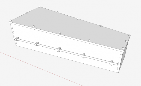
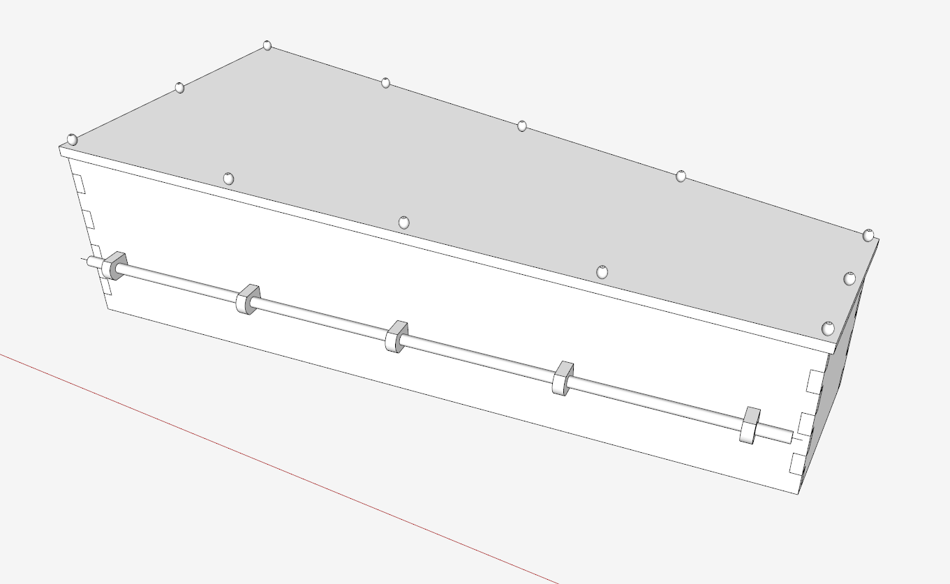
Here it is with the top hidden….
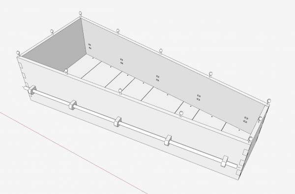
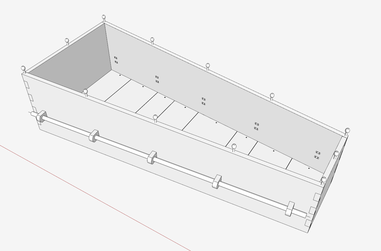
Here is the view with the Side hidden…..
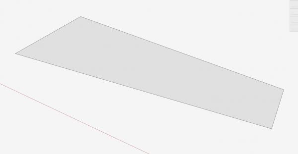
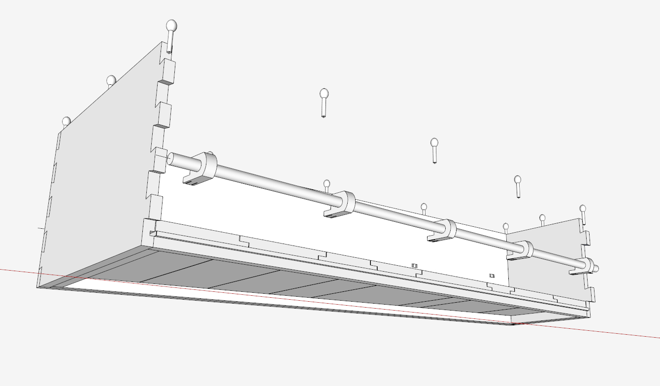
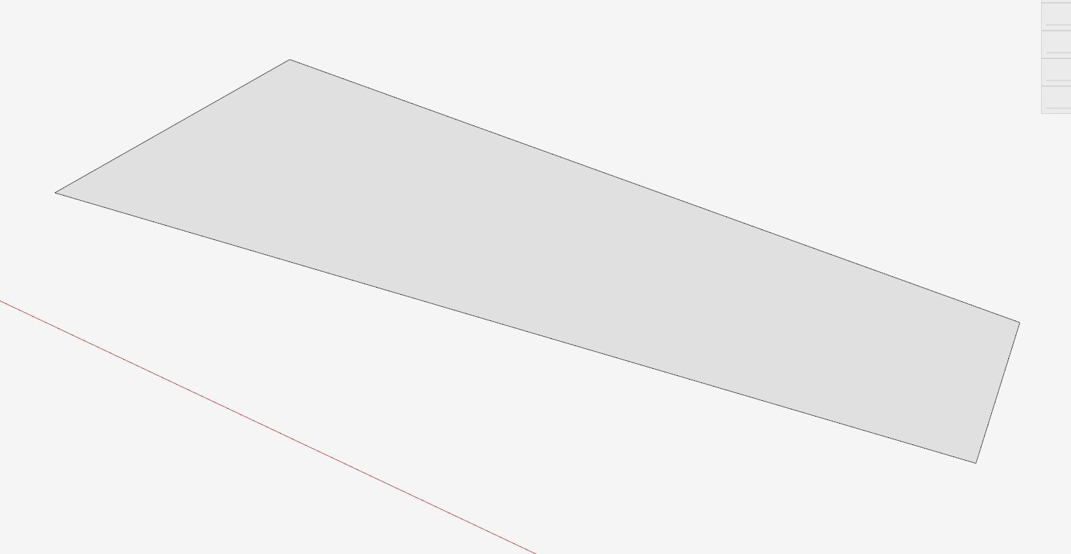
So I start with a shape and size of the Bottom. The outside perimeter of this face represents the inside dimension of the box. To create the Side, I pick the Line Tool and raise up to the height at the Foot end. Then I establish the higher length at the Head End.
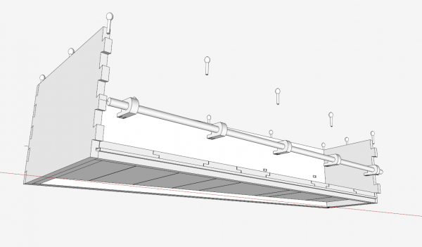
From this bottom form, I create the Side and Foot End components. I will make them 1/8-in. longer at each end to ensure a good intersection at the dovetail joints. Since these components are 1-in. thick, that will give me 1/8-in. extra at each end joint. I like to have this extra length in the shop made components as well. After creating and gluing the dovetail joints, I hand plane the joints to remove all the extra material.
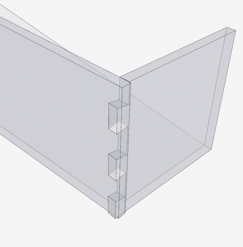
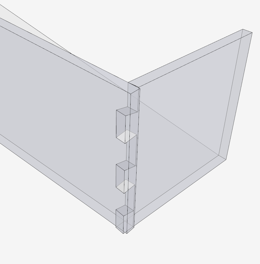
Here is an X-ray view of the dovetail joint with only half the joint finished. I’ll do the rest in another video.
Tim




Comments
Tim,
Won't this layout method (tails first square across the foot board) make pins that are wider at the ends than the base resulting in a joint that can not be assembled with tight fitting pins? Or have you determined that at this slight angle the difference is not significant.
DavidAHood,
I think you are right. I can install each of the Sides into the Foot End, by pushing the Sides along their angled axis. But then how do you push the Head End into the other end of the Sides? It would not go without some distortion, crushing of the joints. I can see that tiny interference when I perform the assembly in SketchUp. You could probably make it work with some force, but it isn't right.
So I will re-think the making of the dovetails so that both the Head End and the Foot End can be pushed straight into the Sides (while angled) on the common Red Axis.
Thank you very much for pointing out this issue.
Tim
DavidAHood:
I spoke too quickly, as I believe my current design works fine. As mentioned in my previous note The Foot End should be assembled first by pushing the Sides into the joints on the axis of the Sides. Then the Head End will push in fine, like a cork, as the angles are opposite.
The sequence, Foot End first, then Head End, is important while in the assembly and gluing process.
Tim
DavidAHood, I re-read your comment and finally understand what you were trying to tell me regarding the layout of the dovetail joints.
I indeed created a joint that would not work with tight fitting pins and tails, rather there is a very small interference by my laying out the tails square across the foot board.
I have corrected that layout error in another video shown here:
http://youtu.be/ws3VhEEQSTc?list=UU1pIa0qnoERn5zoFytwoA_Q
It is a subtle difference but one that I should have seen in the beginning. Again, thanks for the feedback.
Tim
Log in or create an account to post a comment.
Sign up Log in