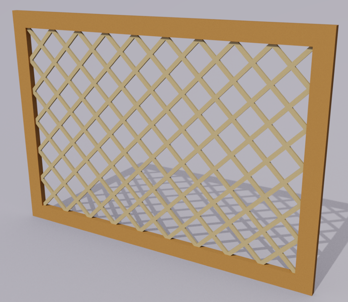
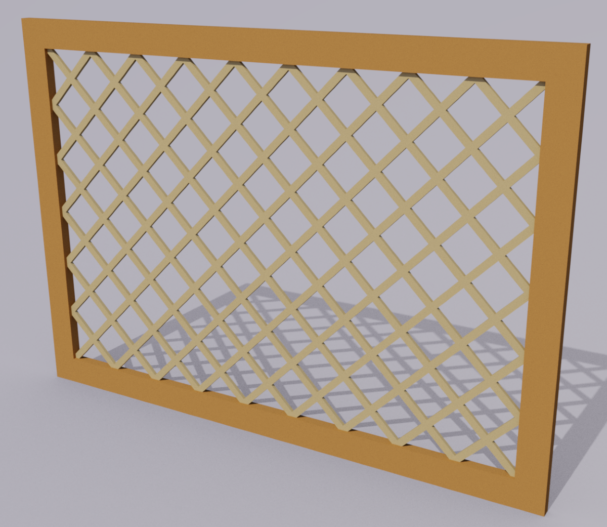
I was having a conversation with a friend who designs some beautiful high end kitchens and other interior spaces using SketchUp. He was showing me a sliding pet gate that his client wants to incorporate into their home. We was looking for a fast, low effort way to draw the lattice work on the gate. Here’s the method I worked out for him. It’s similar to the method I showed on the Chinese cabinet but there are some differences that streamline the process a bit since the pattern is much more regular.
I’m showing this with a simple diamond shape but the same process could be used for other patterns such as clover leaves or fleur-de-lis.
In this example, I leverage the linear array function of Move/Copy several times as well as Edit>Paste in place. I think there’s also an intersting lesson about drawing what will become the negative space and deriving what you actually want from it. Once in awhile I find other uses for that thought process when I’m drawing in SketchUp. It reminds me of that old sculptor’s joke. “Q: “How do you carve an elephant?” A: “First, get a block of marble and then remove everything that doesn’t look like an elephant.”
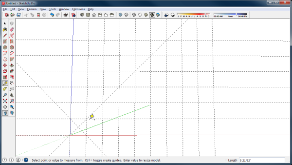
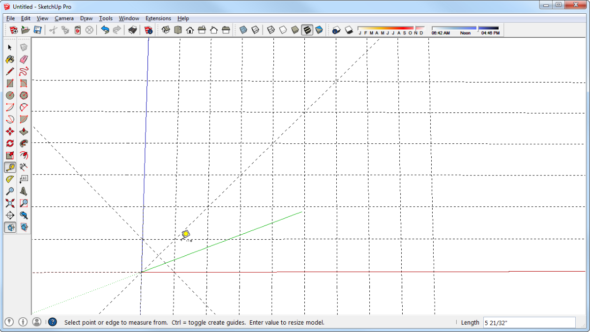
Start by placing a guideline along the blue axis. To do that, get the Tape Measure Tool and double click on the axis line. Next make a grid or an array of guidelines. Select the vertical guideline–I find it easiest to drag a right to left selection box around part of it–and then get the Move Tool. Hit Ctrl to invoke the copy function (Option on Mac) and drag a copy over to the right to the full width of the lattice area. In this example I made it 36 in. Then hit Enter and immediately type the desired number of spaces between the left and right sides of the lattice. In the example I made 9 so each space is 4 in. wide. The space width doesn’t really matter, though and it could be anything.
Since I am creating a grid of square diamonds, the spacing vertically needs to be the same as the horizontal spacing. Here’s a quick way of creating the grid. Select all of the vertical guidelines, get the Rotate Tool and hit Ctrl to invoke the copy function. It would be Option on Mac. Make sure the protractor is showing in green and click at the origin to set the center of rotation. Then click along the origin and drag up toward the green axis line. You should be able to snap the rotation at 90° but you can also type 90 and hit Enter.
Next, use the Tape Measure Tool and click at opposite corners formed by guideline intersections to get a couple of diagonal guidelines in the lower left square as shown above. These diagonals define the centerlines of the lattice “slats”.
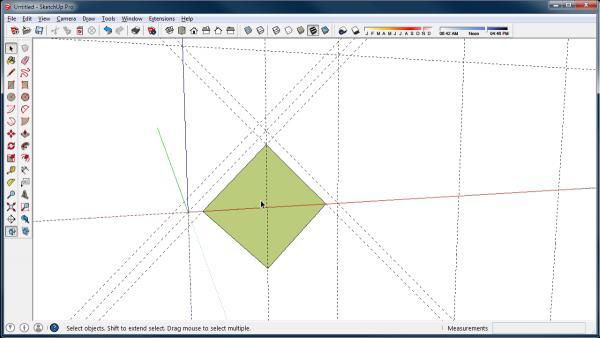
Next place guidelines parallel to the diagonals. The distance is half that of the slats. In my example the slats are 1/2 in. wide so I entered .25 for the diatance. You don’t need to fully define all the slats in the lattice but you’ll need to place a guideline above and to the left of the diagonal guideline passing through the original. This guideline is also .25 from the centerline. While you’ve still got the Tape Measure Tool, put a vertical guideline through the intersection of the diagonal centerlines. That vertical guideline and the one on the red axis identify the center of the square/diamond.
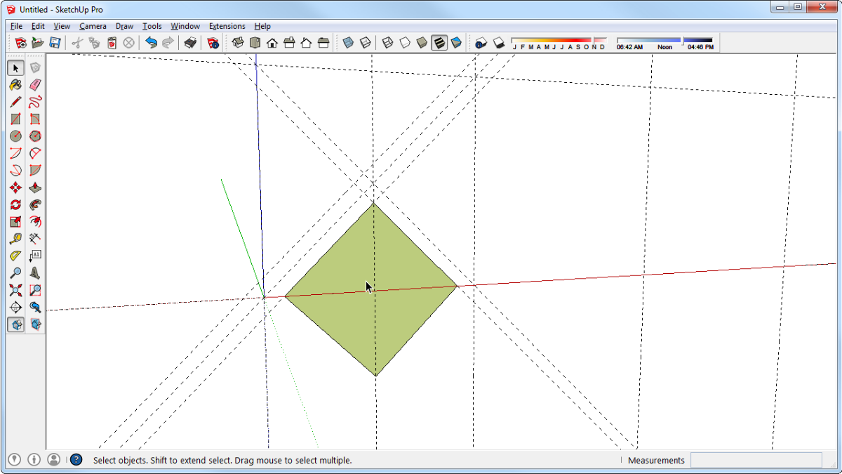
Next you’ll draw the diamonds representing the empty space between the slats. You could use the Rectangle Tool but its easier to use the Polygon Tool. Get the Polygon Tool, type 4 and hit Enter to set it to draw a four-sided polygon. The click at the intersection of that last vertical guideline and the red axis and then click to set the corner as shown, above. No dimension entry is required for this.
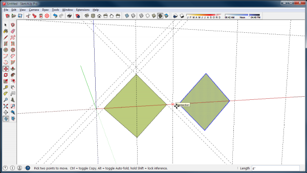
Next, you’ll make the bottom row of diamonds. These will actually only be halves of the diamonds because the bottom edge of the lattice will run along the red axis.
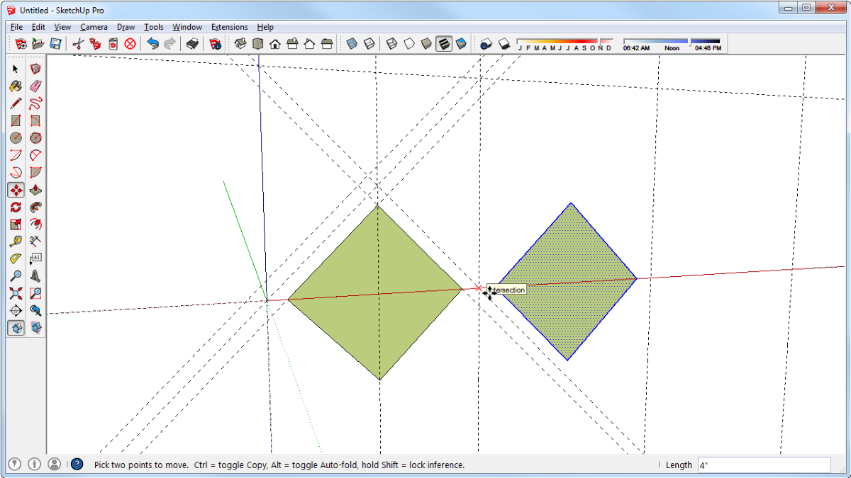
Select the diamond by double clicking on it with the Select Tool. Get the Move Tool and hit Ctrl (Option on Mac) to invoke the copy function. To get the spacing correct, click at the origin and drag over to the vertical guideline as shown in the screen shot, above. In my example that;s moving the copy over 4 in. Then hit Enter.
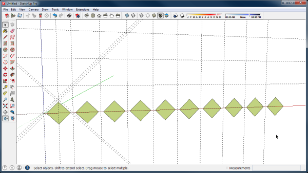
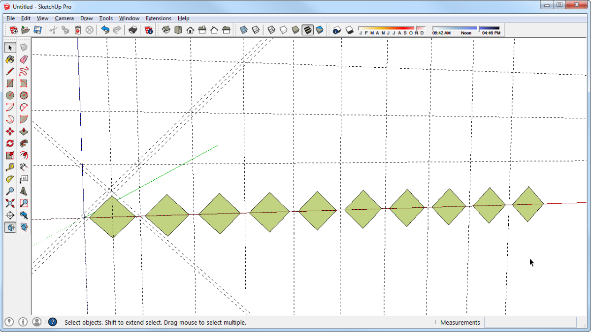
Immediately type the desired number of copies in addition to the original. In my example I made 9 copies. It’s actually one more than needed for this row but the next row will need that one.
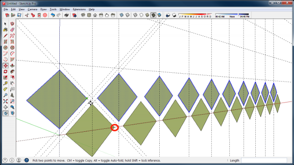
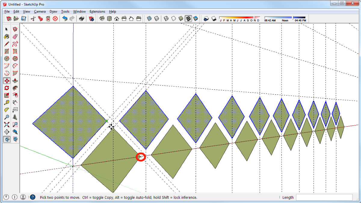
Now select all of the diamonds in the row, get the Move Tool and invoke the copy function. Click at the right corner of the first diamond, indicated with the red circle, and move the copies up diagonally to the point indicated with the green dot, above. Notice this copies the entire row and spaces them properly relative to the bottom row.
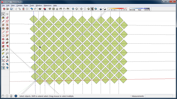
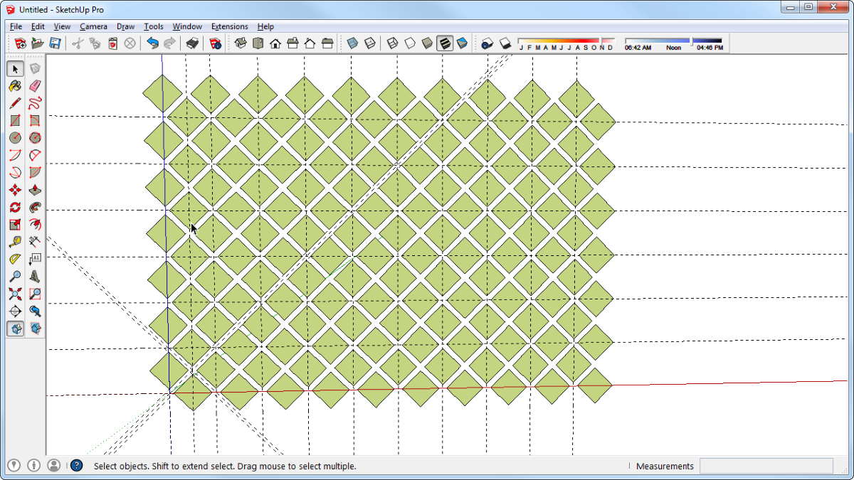
Next select all the diamonds in both rows, get Move and copy those rows up by distance between the two horizontal guidelines. In my example that’s 4 in.. Then immediately type the number of copies. In my example that’s six copies. Hit Enter.
If you squint maybe you can see the lattice in white and the background in green.
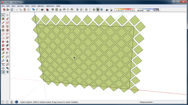
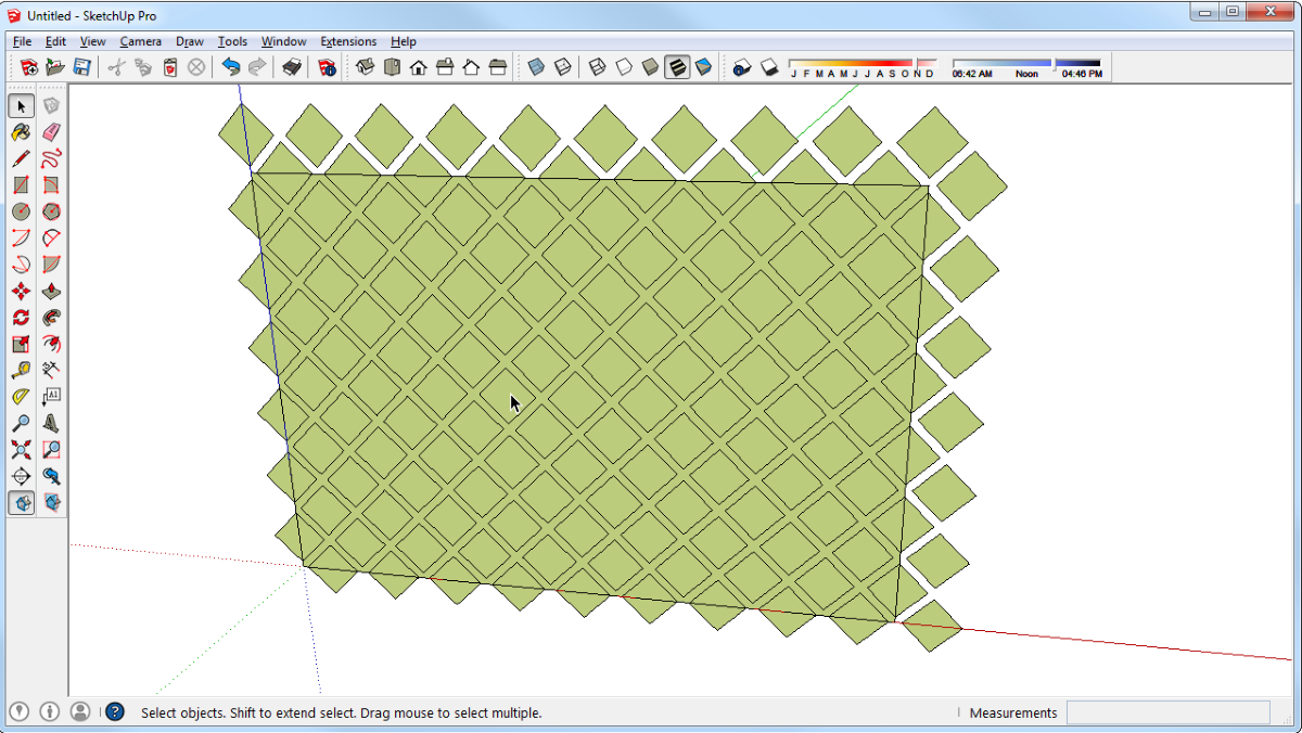
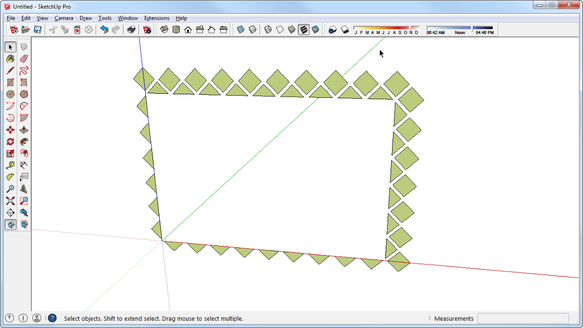
Now get the Rectangle Tool and draw a rectangle to define the outer edges of the lattice. There will be extra diamonds but that’s OK. You’ll get rid of them in a little bit. Now you can see that the space between the diamonds gets filled in.
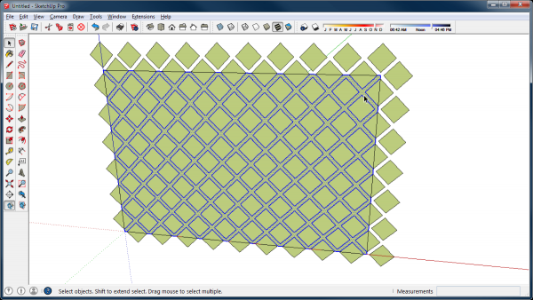
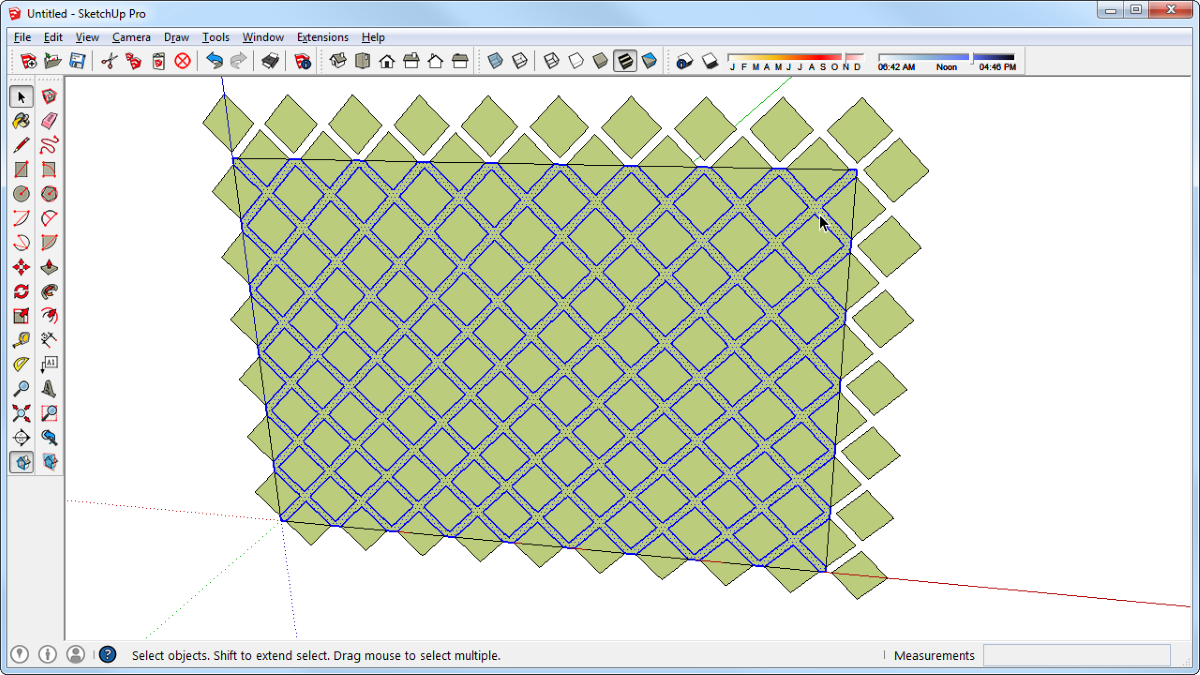
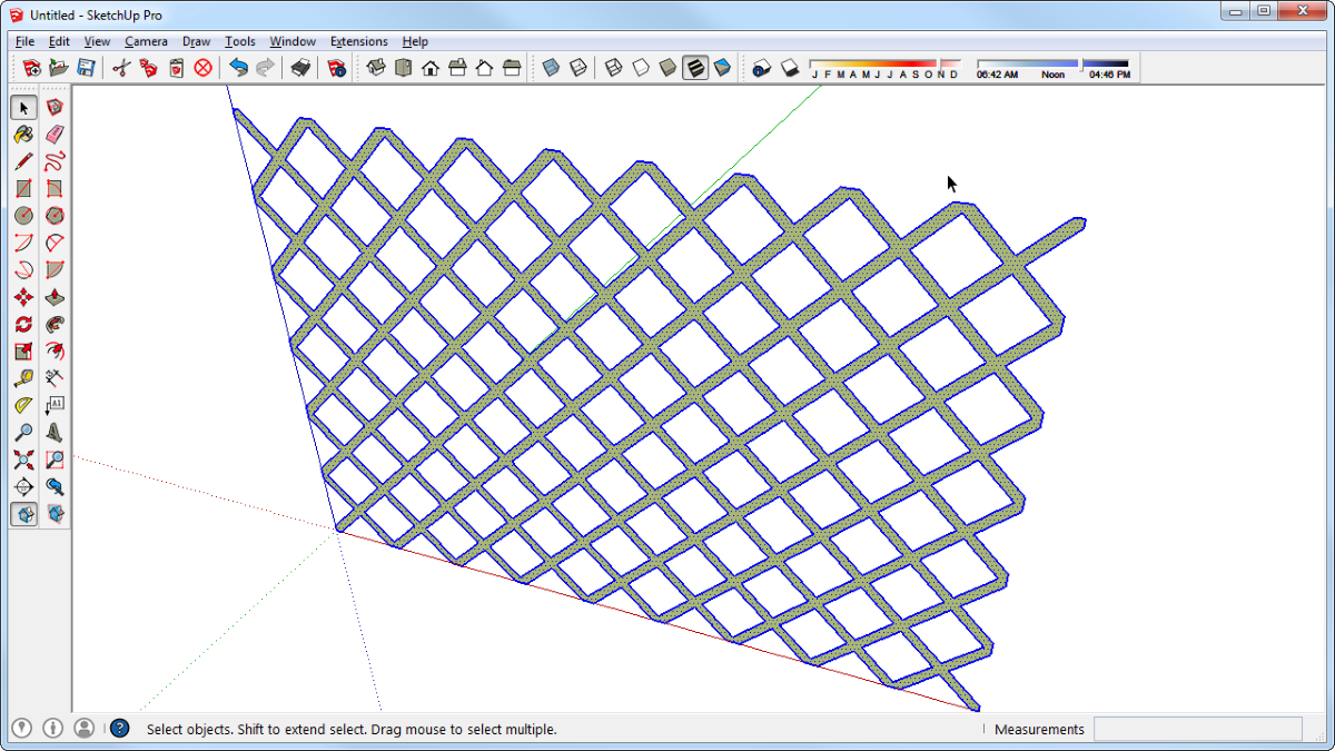
Get the Select Tool and double click on the face between the diamonds. This selects the face and all the bounding edges, above.
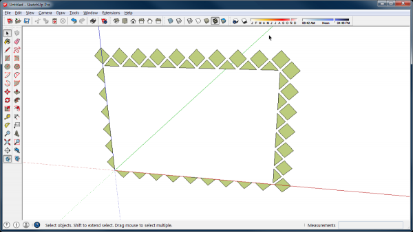
Hit Ctrl-X (Command+X on Mac) to cut the selection to the clipboard. You’ll be left with something like you see above. Then hit Ctrl-A or Command+A on Mac to select everything visible. Hit Delete. The drawing space will be blank but don’t panic.
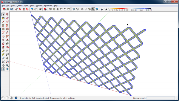
Hit Edit>Paste in place or its keyboard shortcut if you’ve made one. The lattice face will reappear. From there it’s a simple matter to use Push/Pull to give it some thickness and then make it a component.
In this example, the rectangle defining the outer limits of the lattice could have been drawn in advance but if the shaped wasn’t a simple diamond with corners at the edges, drawing the rectangle first would create more work. It would be more difficult to select the bottom row of diamonds without getting the horizontal lines and you would have a lot of clean up to do. after you make the lattice 3D. Edges are automatically broken when they cross other edges. Those breaks in edges would show as lines running on the thin edge of the lattice and those would need to be erased. By saving the rectangle for last, you avoid all that extra work.
I expect you can come up with other applications for this same procedure. One idea might be to use it for drawing a wine bottole rack. Surely there are others but I’m not sure about the elephant.
–Dave



Comments
I still haven't come to the end of the learning curve in Sketchup. Your article was referenced in a forum on 3D Printing with Sketchup. I was trying to create a honeycomb pattern for different pieces and your article was helpful. Who would have guessed you can use the measure tool to automatically set up a grid. There is so much under the covers of Sketchup doubt I will ever "get to the end."
Log in or create an account to post a comment.
Sign up Log in