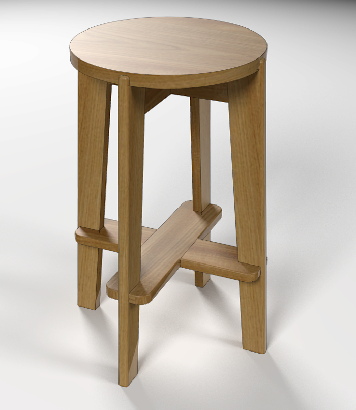
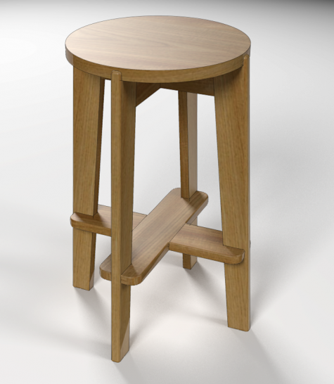
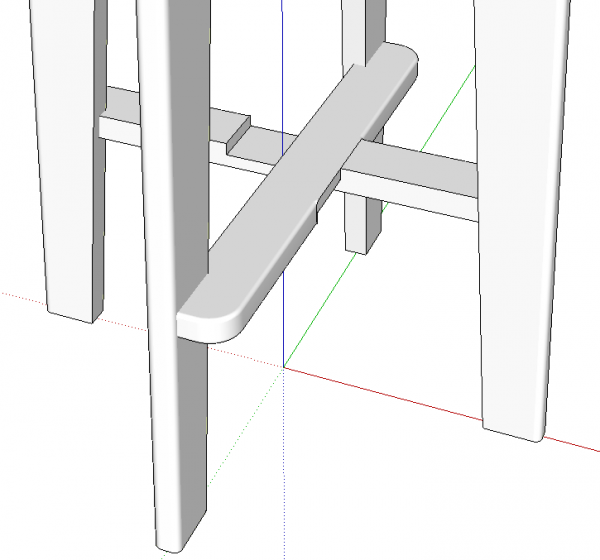
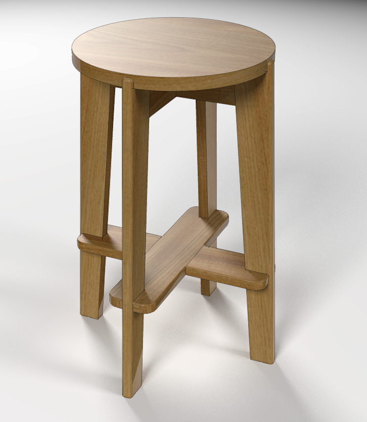
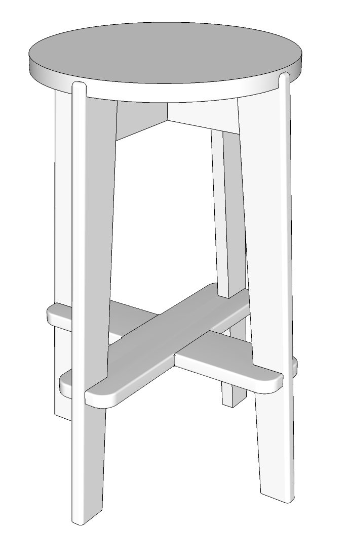
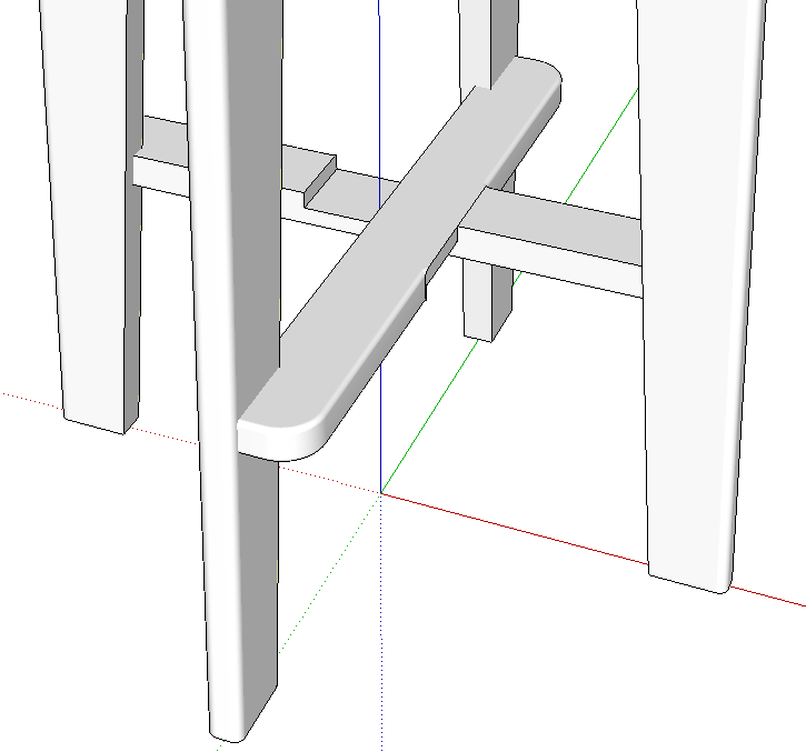
This is a model based on a stool designed by Pierre Jeanneret and manufactured in the 1950’s in both France and India. I came across a couple of photos of an original and decided to use it for my morning SketchUp practice. As I was working my way through drawing the parts, I found an interesting challenge in rounding over the lower cross pieces. They are joined with a half lap joint and it’s clear from the phtos that the edges were radiused after assembly. The round overs don’t extend all the way into the corners where the two parts meet.
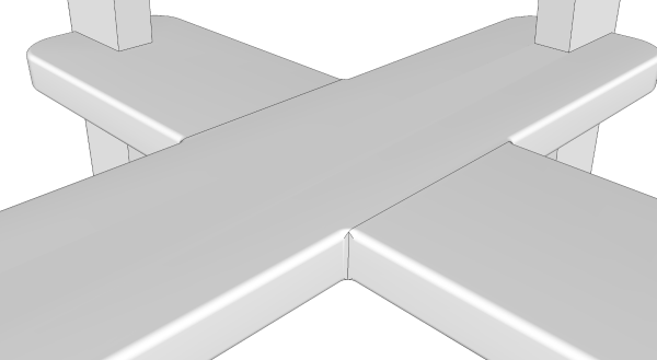
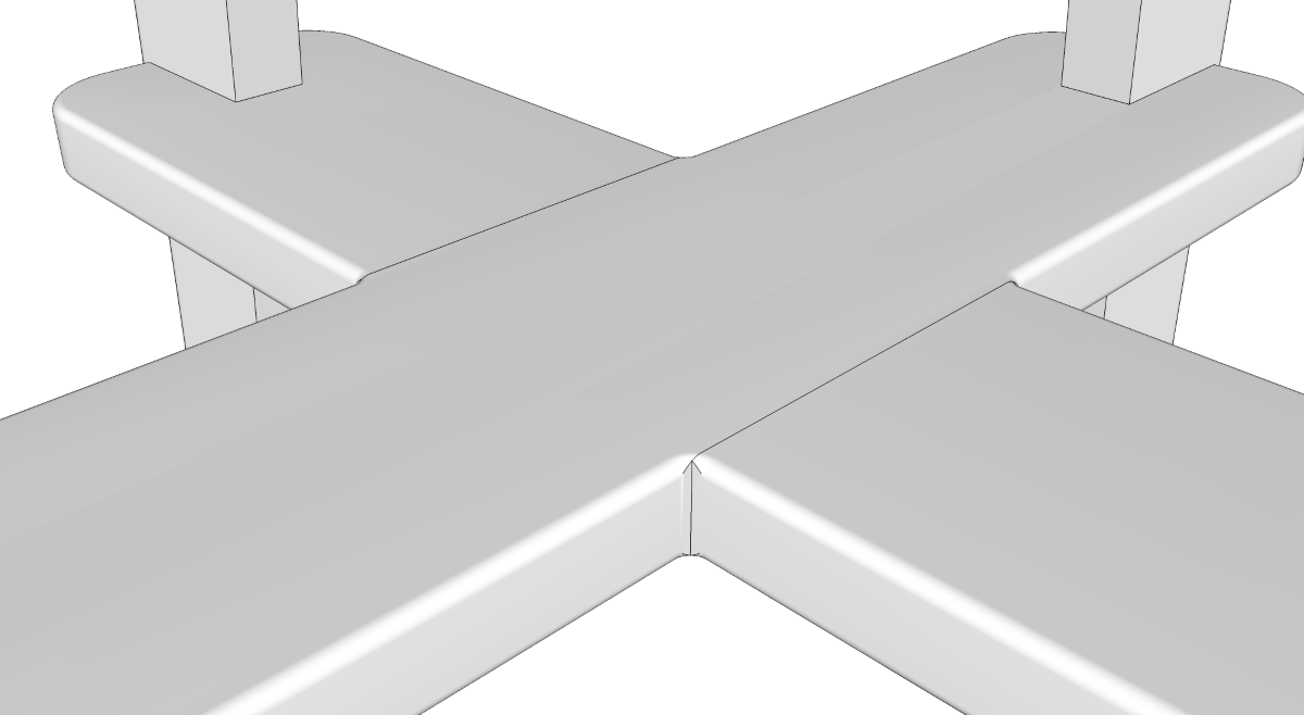
That’s more evident in this close up view. A router bit wouldn’t be able to reach all the way into the corner. Now, if you were making a one off piece with this sort of arrangement, it wouldn’t be a big deal to finish the corners with a file and sand paper. But for something that is mass produced, theese corners probably wouldn’t get that much attention.
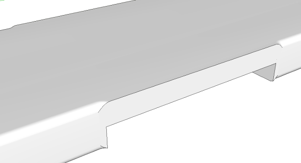
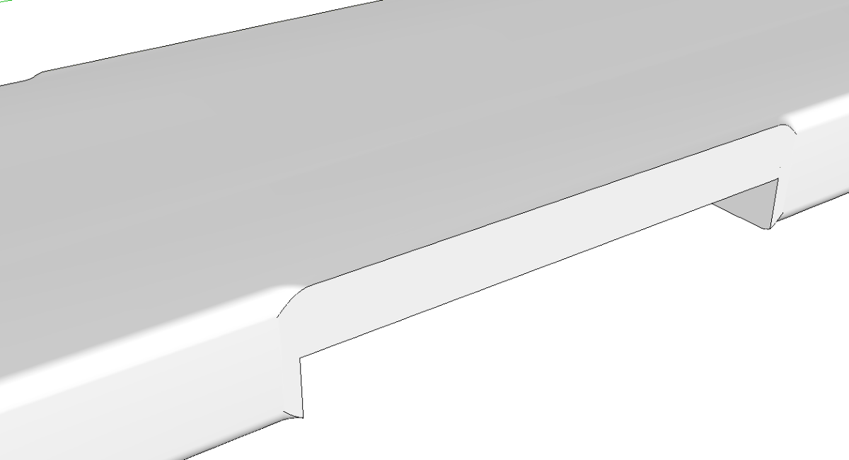
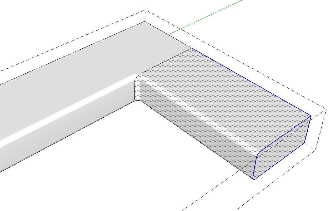
With one piece out of the way, you can see how the radius turns the corner.
I started thinking about an efficient way to draw these radii and also the notch. My first thought was more of a brute force method but that wasn’t clean nor fast. My second approach was much better and perhaps someone can come up with something even more elegant. In any case, here’s how I did it.
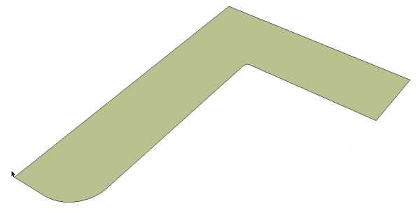
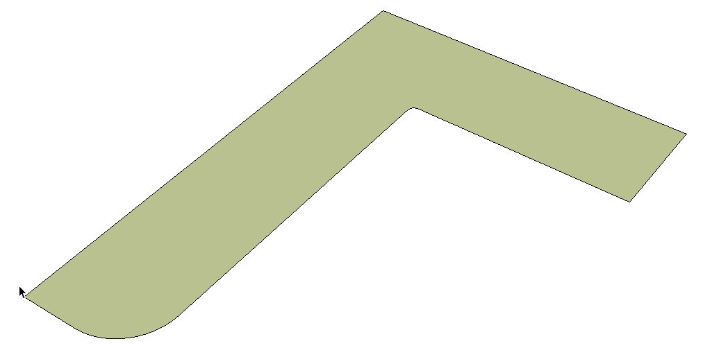
The piece is symmetcrical in both the x and y directions. It’s a whole lot easier to draw a quarter of the part and then copy and flip to get the other three quarters. The left portion of the inverted L in the image above is the part that will be kept. The leg on the right is going to be waste. It forms a sort of limit for where the “router” can run. I added a small radius in the inside corner which represents the radius of the pilot on the router bit.
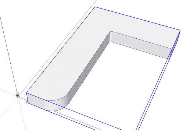
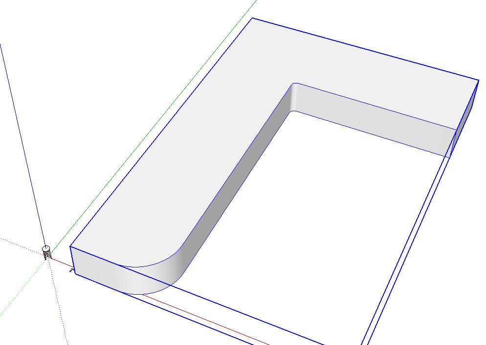
I used Push/Pull to make the geometry 3D and made it a component. Since there will be some very tiny faces in the end product, I made a copy of the component and scaled it up by a factor of 100. I prefer to work on a scaled up copy of the component because when I’m finished with it, I can discard it and return to the original which is still where I left it. Working on the scaled up copy avoids the tiny gaps that can occur when creating small radius curves. You can see the original copy of the part at the lower left corner of the large copy.
Note: if you subscribe to the practice of making groups for one-of-a-kind parts and reserve components only for those parts that have multiple copies, this method won’t work for you. You’ll have to scale the group up and then back down.
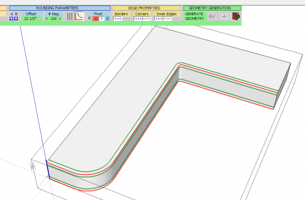
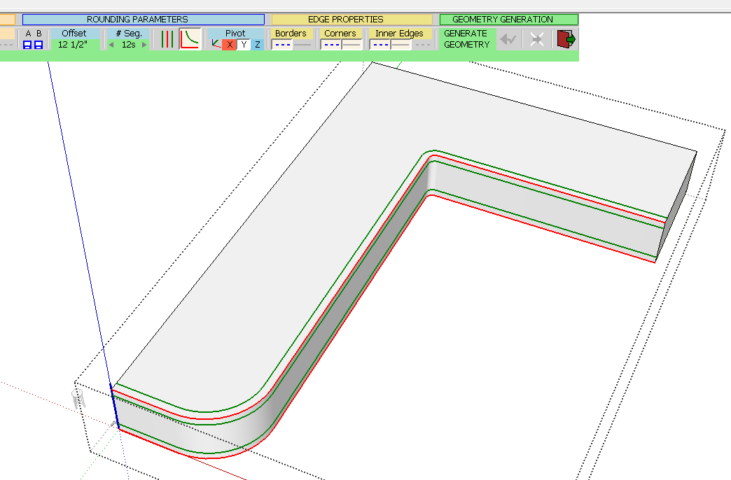
To put the round over on the edges, I selected them and then use Fredo6’s RoundCorner extension. The radius is 1/8″ but since the component is scaled up by a factor of 100, the offset is set to 12-1/2 in. The extension shows in green where the limits of the round over will be so you can change it if needed before running the routine.
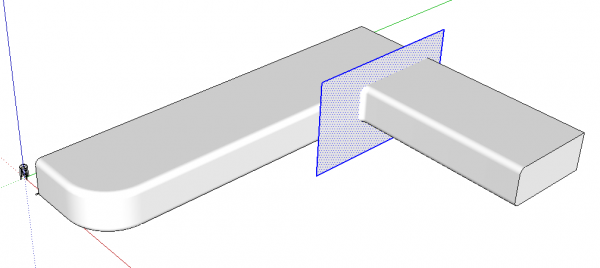
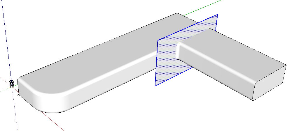
After the routing finishes and the edges are rounded over, you need to cut off the waste. I use a cutting plane for that. I like to draw the cutting plane in place but outside of the component. That way I can make sure I get it located where I want it without risking damage to the geometry inside the component wrapper.
After getting the cutting plane in the right location, select it and cut it to the clipboard with Ctrl-X or Command-X on the Mac. Open the component for editing and use Edit>Paste in Place to put the cutting plane into the component.
Select all of the geometry that will be involved in the intersection, context click on it and choose Intersect Faces>With Selection. There’s no point in making SketchUp look at every face for intersections. That takes time. You can reduce the number of faces that get looked at for intersections by turning on Hidden Geometry in the View menu and then using a right to left selection box around the area of the cutting plane.
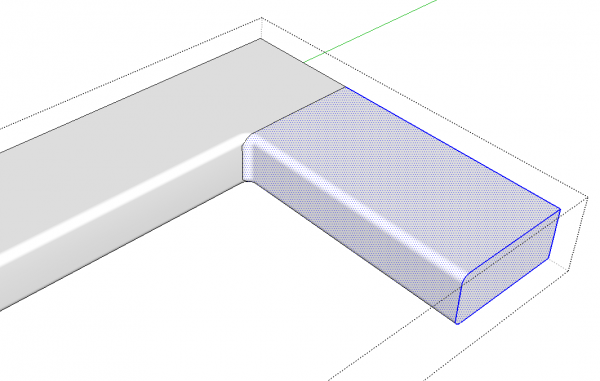
After the intersection is completed, delete the edges of the cutting plane. Then use a right to left selection box around the end of the waste portion of the part. Check to see that the selection stops at the intersection line you just made as in the image above. If the selection is right, hit Delete to remove the waste.
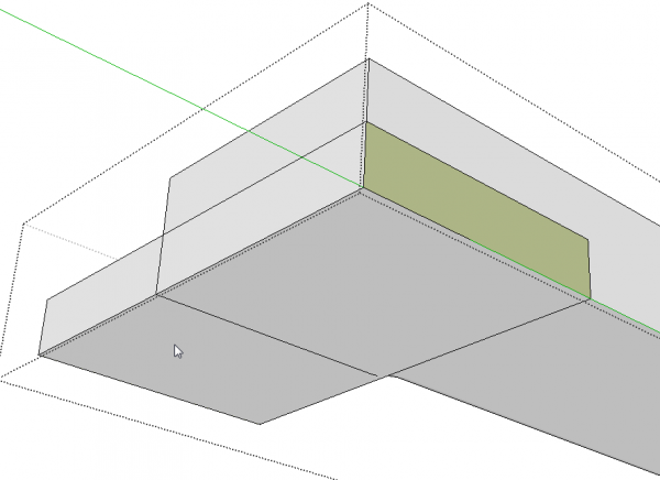
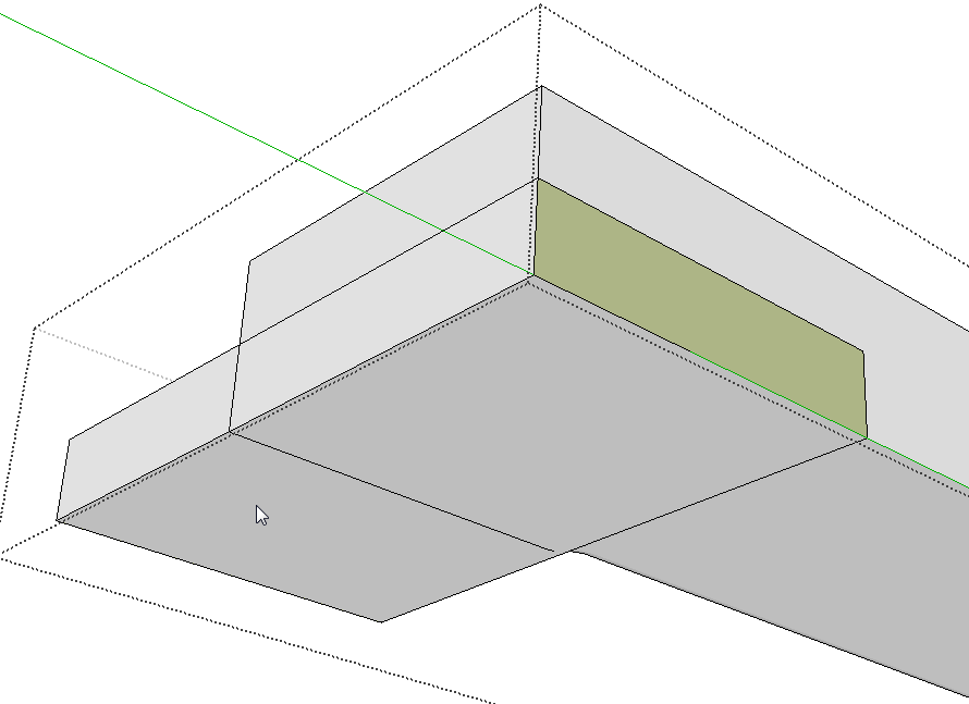
Now it’s time to create the notch for the half lap joint. Orbit around to the other side of the part and draw a rectangle on the vertical face. Then use Push/Pull to push that rectangle through the part and out the other side. Push/Pull will normally stop when it runs up against the curved surface on the opposite side so hit Ctrl (Option on Mac) before you start pushing. That will leave the face and allow you to extrude all the way through. Push it plenty far past the rounded side of the part so you can easily get rid of the waste.
You’ll need to create some intersections that won’t happen naturally so select the involved faces as before and run Intersect Faces>With Selection.
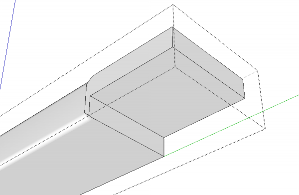
Erase the waste and correct the face orientation and the notch is complete. Now it is time to make the rest of the part.
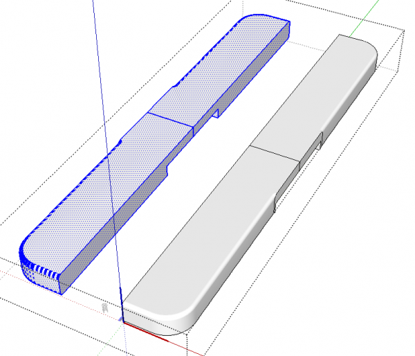
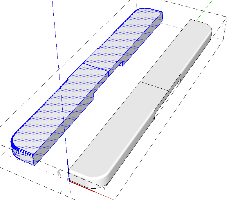
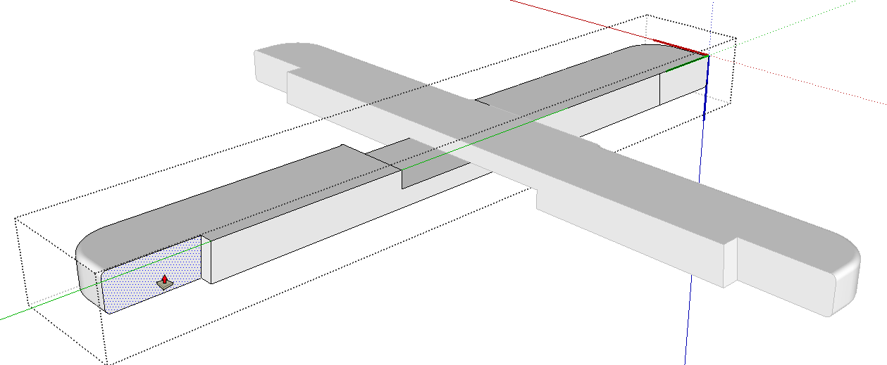
Select all of the geometry you’ve created and use Move/Copy to copy it. In the image above, I’ve first copied it in the green direction and then flipped the copy along the green direction. Then I moved the copy back to join the original. Next, I selected and copied the entir right half and copied that over to the left before flipping it along the red direction. When you do this sort of thing, make sure you move the copy far enough away from the original so that the geometry can’t intersect the original before the flipping operation is complete. When you move the selection back over to join with the original, make sure you grab it with the Move tool on the seamline. That way you can snap the copy to the original in the right place.
Once you have the whole piece created, erase the seamlines and then close the component either by clicking with Select out in space or hit the Esc key. The select the component–blue bounding box–and hit Delete. Use Zoom Extents to return to the original which will also be complete.
In the case of this stool, the crosspieces also need to get notches in the ends. Probably the easiest way to do this is to wait to complete the parts until after the notches are drawn. So you might wait to make the copies of the quarter until after you added that notch and it’s easiest to add the notch using the leg of the stool as a reference.
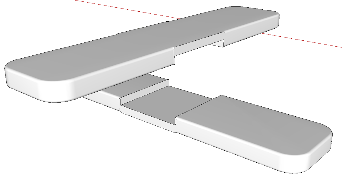
For this example, I did complete half of the crosspiece for clarity. Copy/Rotate and flip the copy so the half lap joint will fit together correctly. Then make the copy unique.
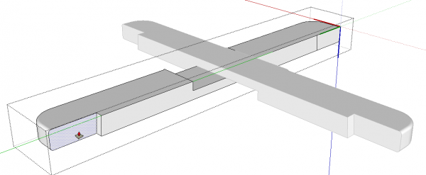
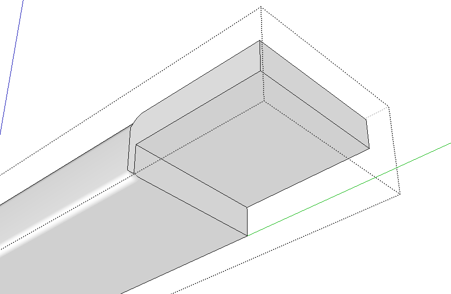
Open one of the components and use the Line tool to trace the inside edge of the leg. Then use Push/Pull to push away the notch. I hid the legs for the image, above, but in practice, I would normally do this “by feel”.
After the notches are completed, copy and flip the geometry as described above and delete the seamlines.
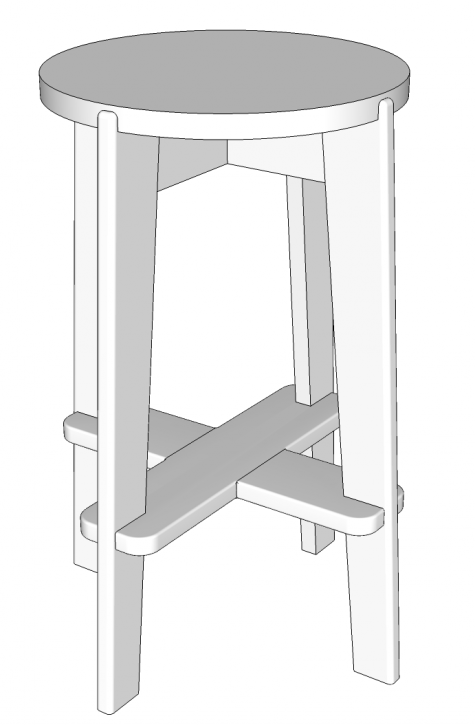
And presto! The parts are finished and they fit properly between the legs.
The process seems like a long drawn out procedure but once you’ve got the steps sorted out, it goes quite rapidly. The key thing is deciding in which order to complete the steps. Sometimes the easiest order isn’t the most obvious. If you add detailing like this to your models, you can probably find other applications for this sort of procedure, too.
–Dave
After sleeping on it occurs to me that it would be better to create a lap joint between the leg and stretcher. If the joint is cut in the leg so it is horizontal, both stretchers could be identical. Fortunately, that’s a modification that’s easily made in Sketchup. -dr



Log in or create an account to post a comment.
Sign up Log in