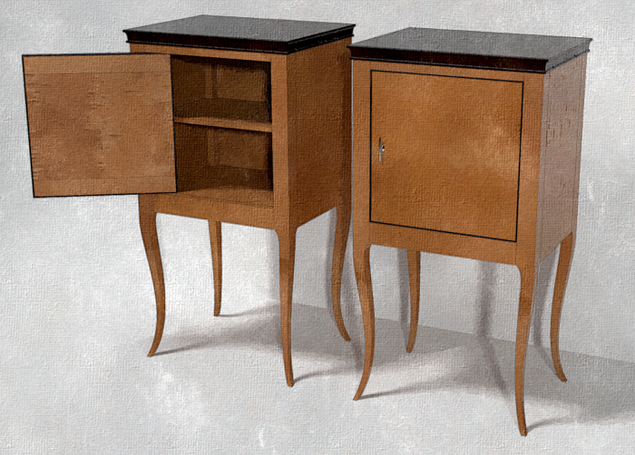
How do you draw a leg with two different curves? Of all the questions I get related to drawing in SketchUp, I think this one must rank right up there among the most common. I think I’ve covered this in the past but it is worth considering again.
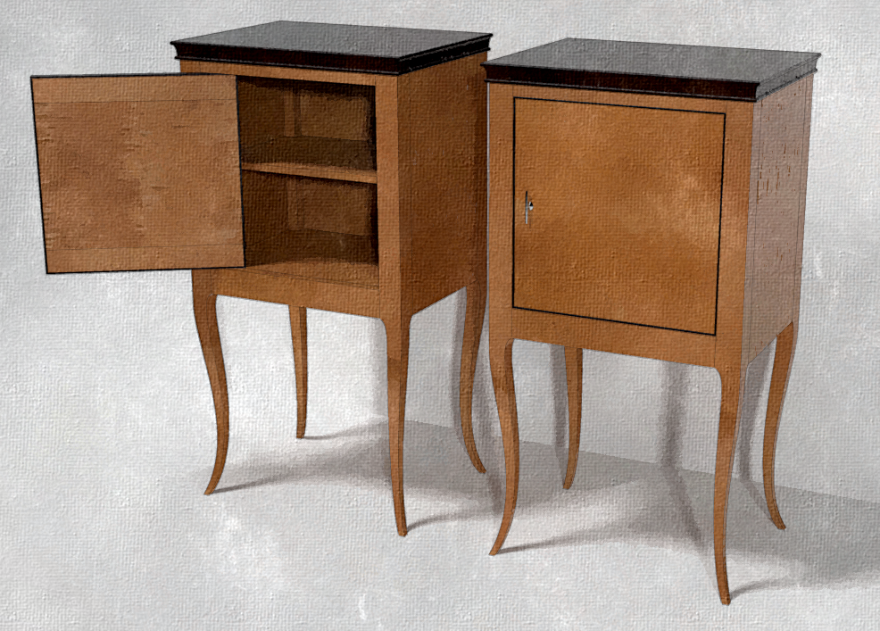
In this case I’m using a model of a pair of Italian Neo-classical bedside tables. The originals date to around 1835. The legs are a cabriole-style similar to those found in a number of styles of furniture such as Greg Arceneaux’s Louisiana Creole Table , from Fine Woodworking #238, pp. 50-57 December 5, 2013. You might also see a similar idea on some Asian-influenced pieces in which the legs have larger feet and curve gracefully toward the top.
The basic process of creating these legs is very similar to the process you would use in the shop. Starting with a blank large enough to get the leg out of, cut two sides and then cut the other two. In the shop, you would typically tape the first two waste pieces back on to the leg as supports for making cuts three and four. Of course in SketchUp, you don’t need to do that.
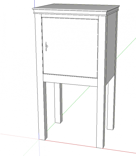
To start, draw the full leg blank and make it a component. Here I’ve drawn the rest of the model as well. I find it helpful to have that context when laying out the curves for the legs, especially if I’m working to a photograph of the piece. I started with the left leg and after making it a component, I copied it into the other three positions making sure the right front leg was flipped along the red direction and the two back legs are flipped in the green direction. This creates mirrored copies so that the details on the legs get added in the right place. Note that flipping is not the same as rotating them. Rotating the components does not create mirrored copies.
If you are thinking ahead a bit, you’ll realize the front and back legs need to be different due to the joinery. The front legs need to get dovetail sockets for the top rail and small mortises for the rail below the door while the back legs will get long mortises for the tenons on the back panel. Those details get added after the legs get shaped.
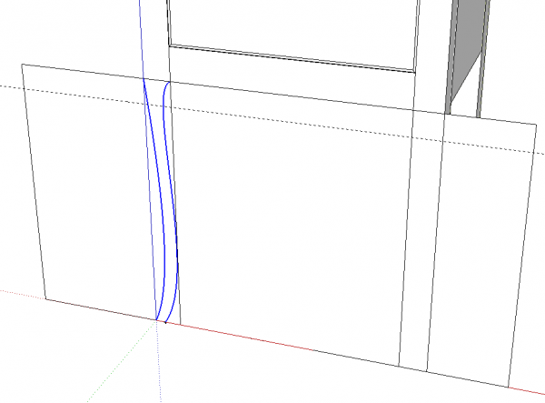
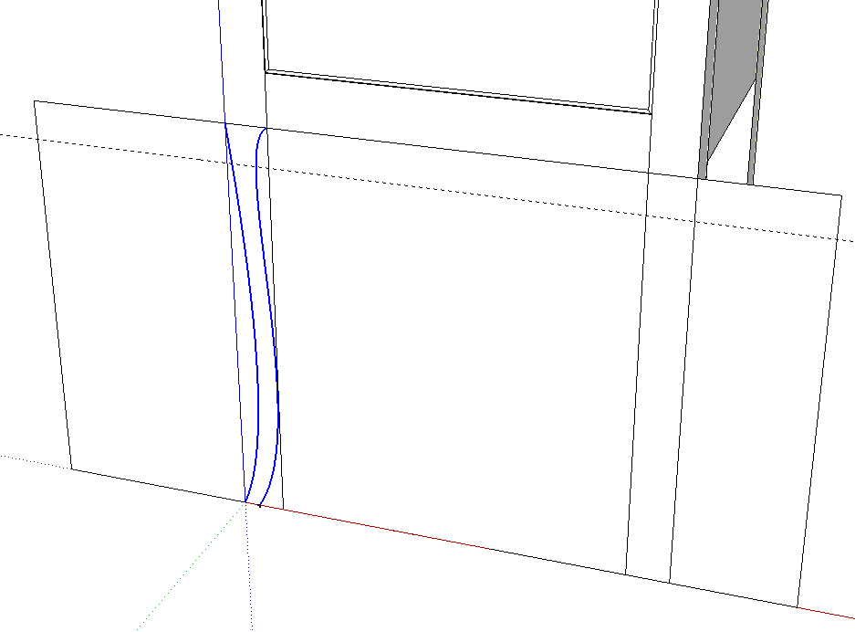
I like to draw the curves outside of the leg component so that I don’t need to worry about them intersecting the edges of the leg before I’m rady for that. I drew a rectangle as a working surface because the Bezier Curves tool from the Bezier Spline extension is happy to draw curves in 3D space but in this case the curves need to be flat.
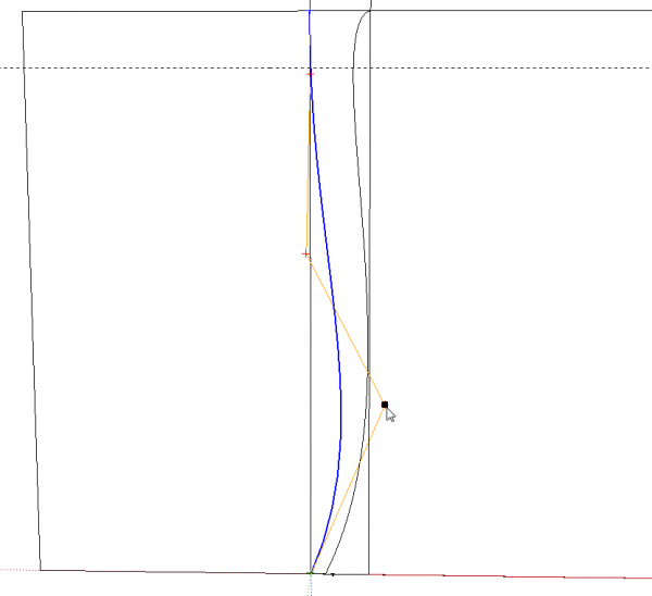
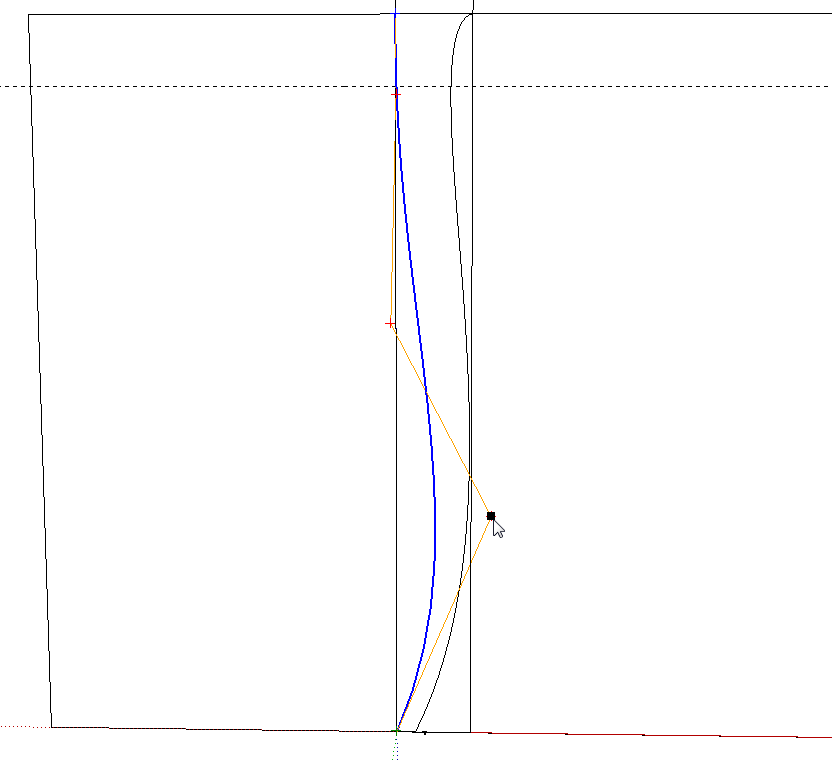
When you draw the curves initially, just get them roughly in place. Don’t spend a lot of time at first trying to get them right. In this case, you’ll want to be able to look at both curves together. After you’ve placed both of them, you can edit their control points and tweak the curves. Right click on a curve and choose BZ – Edit Classic Bezier Curve. Move control points as needed and even add more if you wish by double clicking on the orange line. You’ll probably find you need to work back and forth between curves to get something pleasing. This might seem to be kind of tedious but it’s a whole lot easier than redrawing curves on paper until you get them right. Make sure as you are tweaking the curves that you don’t let them run outside of the edges of the leg. If they do, you’ll wind up with flat spots just like you would if you were cutting the leg on the bandsaw and followed the curve off the leg.
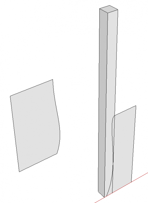
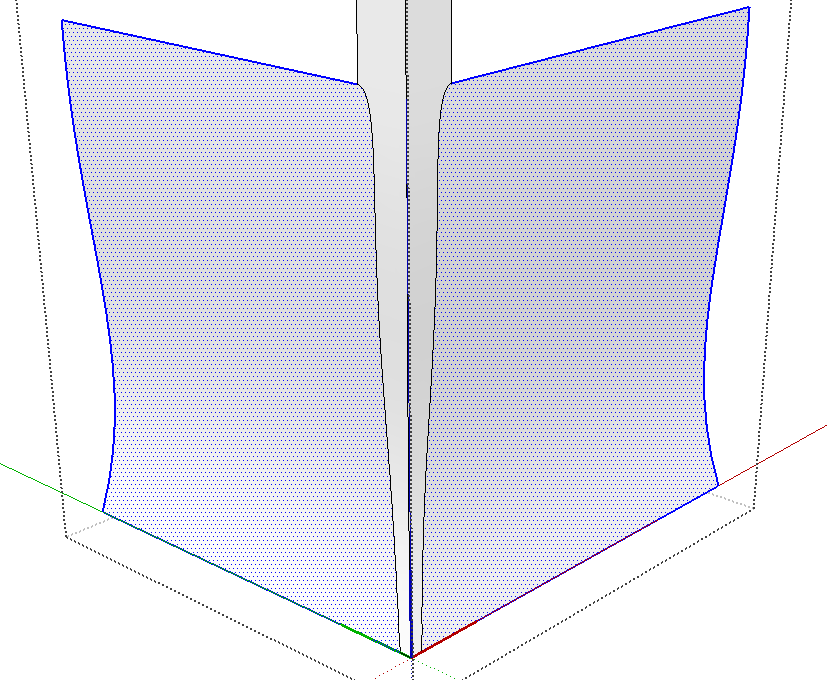
Once you are happy with the curves, it’s time to make two “cutters”. Erase the edges joining the curves at the top and bottom. These edges are part of the original rectangle. Erasing them divides it into two sections. Think of these as giant shaper cutters if you like.
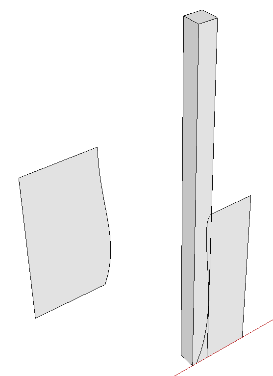
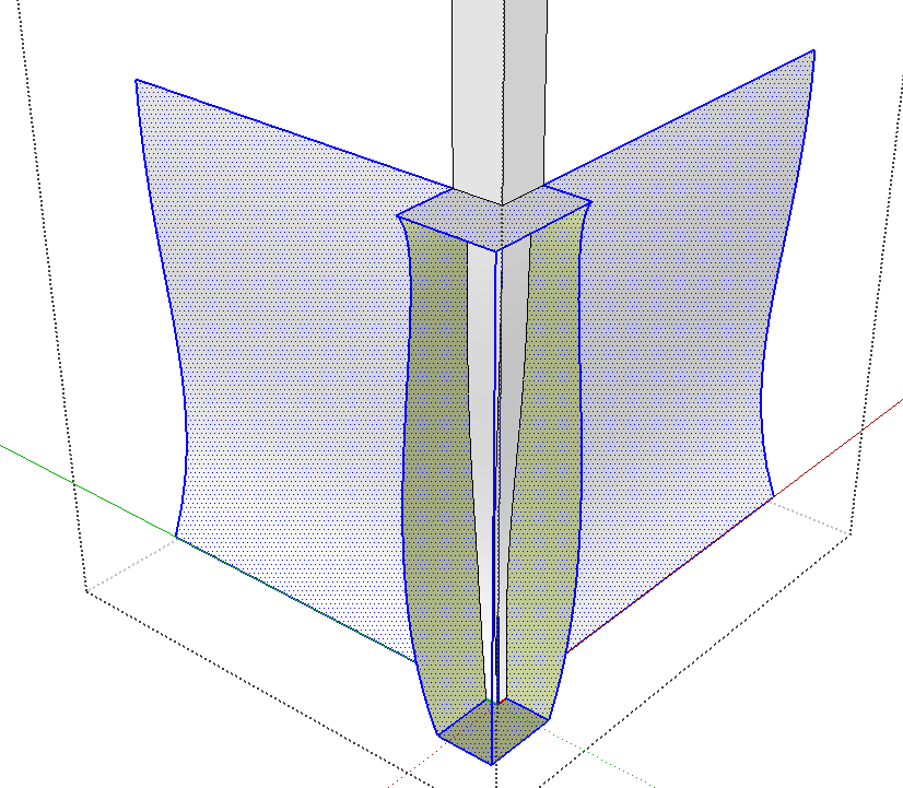
In the image above, I moved the cutter for the outside faces, on the left, out behind the leg. The cutter for the inside faces is left in place on the leg. The exact distance you move the outside cutter back isn’t important but doing this makes it easier to clean up the waste geometry later. It is important to move the cutter on axis though so it remains properly aligned with the leg.
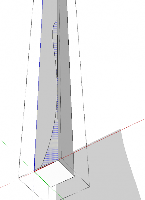
The next step is to cut the two inside faces of the leg. For this all you really need is the curve but it needs to be in the component context. Erase the straight edges leaving just the curve. Then select it, and use Edit>Cut to put the curve on the clipboard. The keyboard shortcut would be Ctrl-X or Command-X on Mac. Then open the leg component for editing and use Edit>Paste in place to paste the curve into the component.
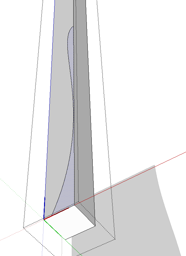
Check to see that the curve divides the surface into two faces by selecting one and making sure the face on the other side is not selected as shown, above.
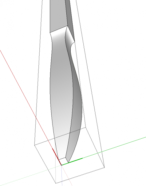
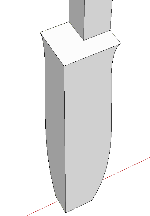
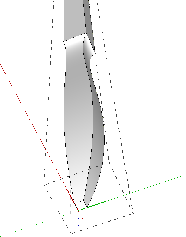
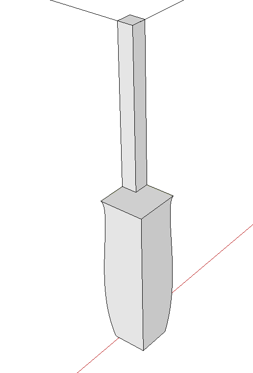
Select the bottom inside edges of the leg, get the Follow Me tool and click on the face on the waste side of the curve. In the blink of an eye you end up with something like that shown above.
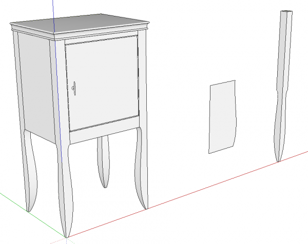
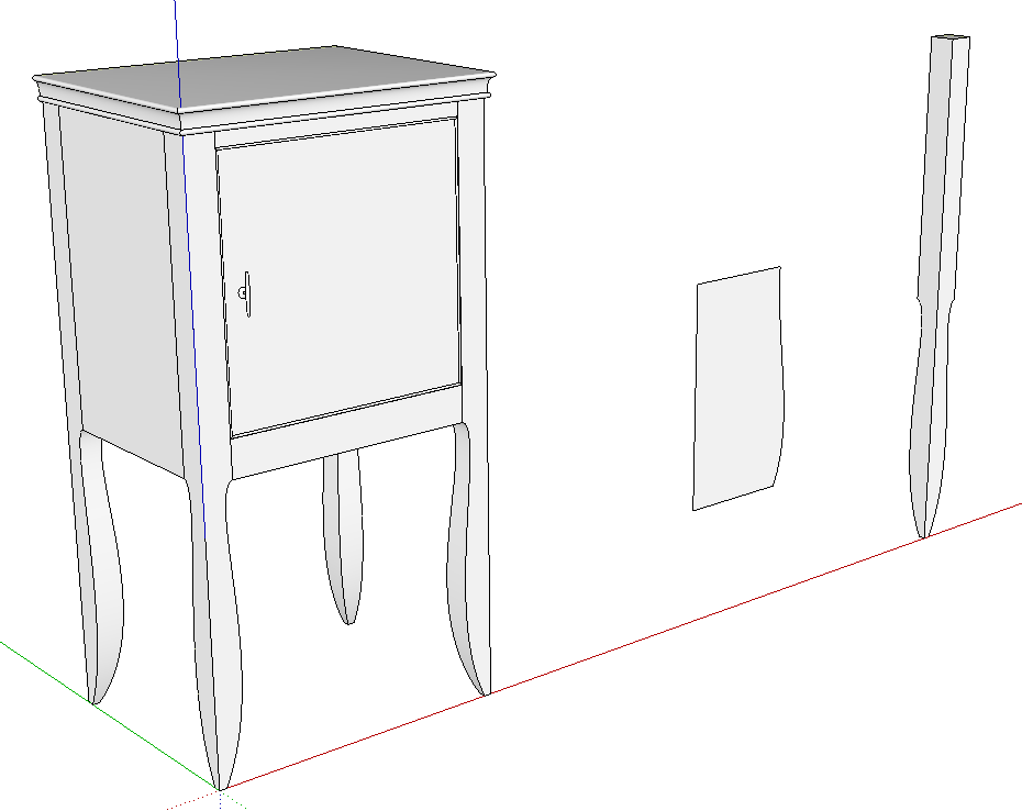
Since the legs are instances of the same component, you can see that all four have been cut to shape along with the copy that has been getting edited.
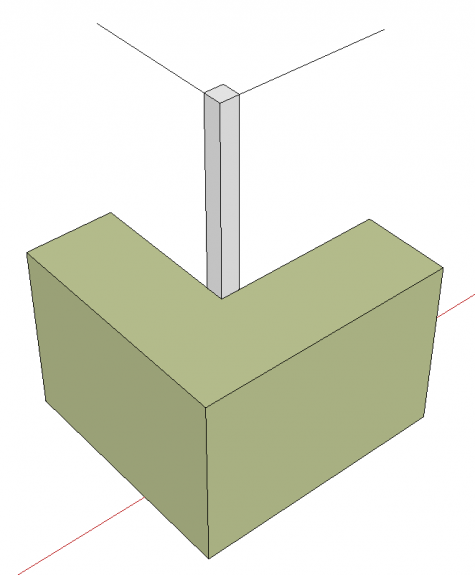
Now it’s time to move on to shaping the other two faces. This needs to be done a little differently, though. This will use another Follow Me routine but this time it’ll be done outside the component and the resulting extrusion will then be copied into the component to do the cutting. By doing this you can make sure the leg doesn’t get modified before you re ready.
I drew a couple of lines to act as the path for Follow Me. I drew them at the top so you can see them with the resulting extrusion but if you draw them at the bottom, you’ll save yourself an erasure step later.
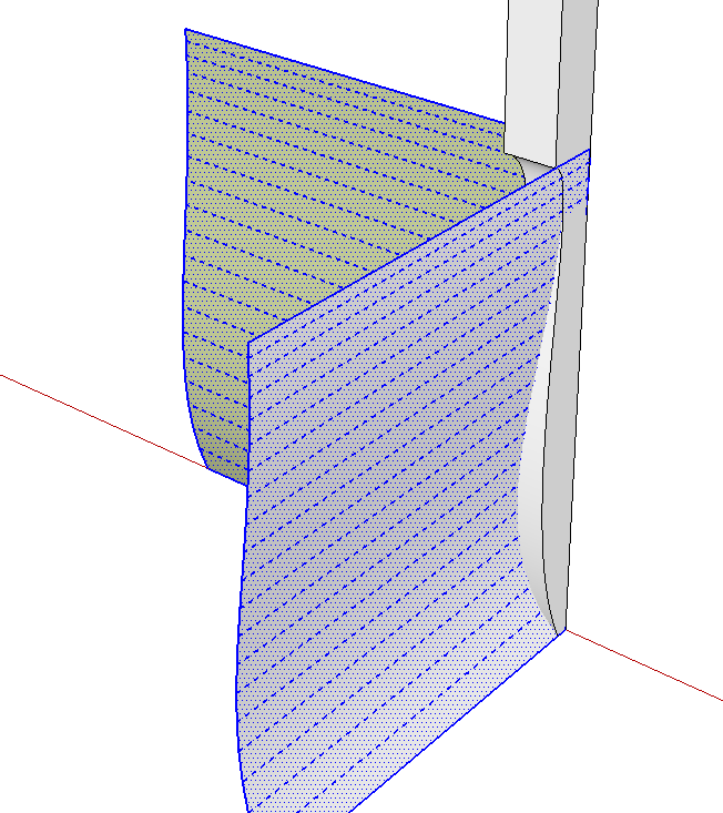
With those two lines selected, get Follow Me and click on the remaining cutter face. Notice how the extrsion runs well off the leg in both directions. This makes cleanup easier later. I think of this as starting the cutter moving before the wood is brought into contact with it and shutting it off after it is off the work.
In my example, the extrusion is inside out. The green faces are the back faces. That actually works out fine because at the end, the visibile surfaces will be some of the inside faces of this extrusion. If you get outside faces with this extrusion, you can either reverse them now or fix them later. It doesn’t matter much when you do it but make sure you correct the face orientation so front faces are out.
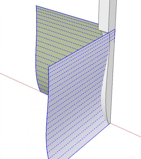
Here you can see that I’ve erased all of the extrusion excepth the curved surfaces and that they are correctly oriented. Select the surfaces and cut them to the clipboard using Edit>Cut. You’ll then open the leg component for editing and use Edit>Paste in place to paste the curved surfaces into the leg. I use Paste in place so much that I created a keyboard shortcut for it. You might find it worth doing, too.
After pasting the curved surfaces into the leg component, select all of the geometry of the curves and the leg, right click and choose Intersect Faces>With Selected. After the intersection is complete, erase the waste and the leg is finished.
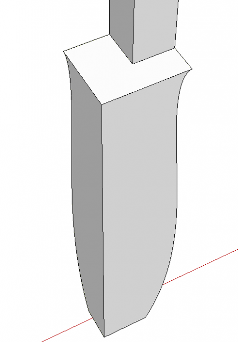
I found that the entry angle relative to the sides of the leg for the top of the curve I drew is so shallow that SketchUp wasn’t making a complete intersection there. I was running up against the tolerance limits inherent in the program. To get around that problem, I edited the leg to add a bit of meat. I drew lines on the outside faces at the tops of the curves and used Push/Pull to pull the lower faces out.
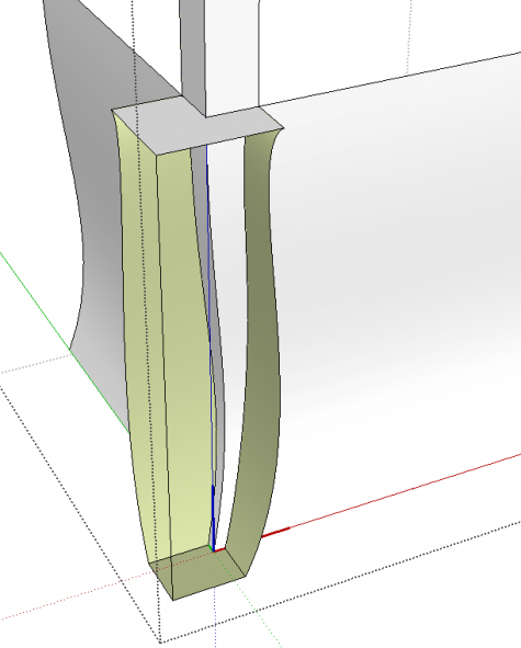
After pulling those faces out, I used Paste in place to paste the cutting curves into the component. Then I selected all of the geometry and used Intersect Faces>With Selection. After that it is just a matter of deleting the unneeded geometry. In the image, above, I’ve erased the two out faces of the leg.
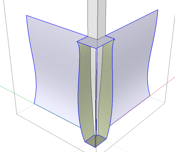
I’ve found the fastest way to get rid of the unneeded geometry is to to drag right to left selection boxes around the outer ends. This selects any edges and faces that fall even partially inside the selection box. As long as you don’t include in the selection any of the edges or faces of the part you need to keep, you can just hit delete and get rid of the waste and leave the leg intact. Since the curves get exploded during the Follow Me operations, getting all of those little line segments with the Eraser tool could be quite time consuming.
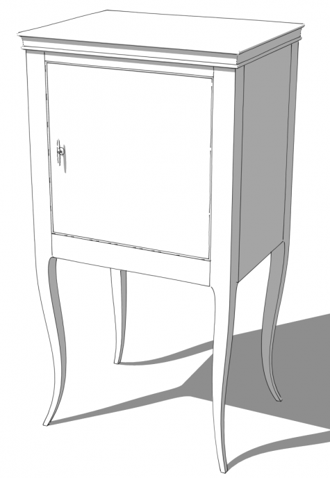
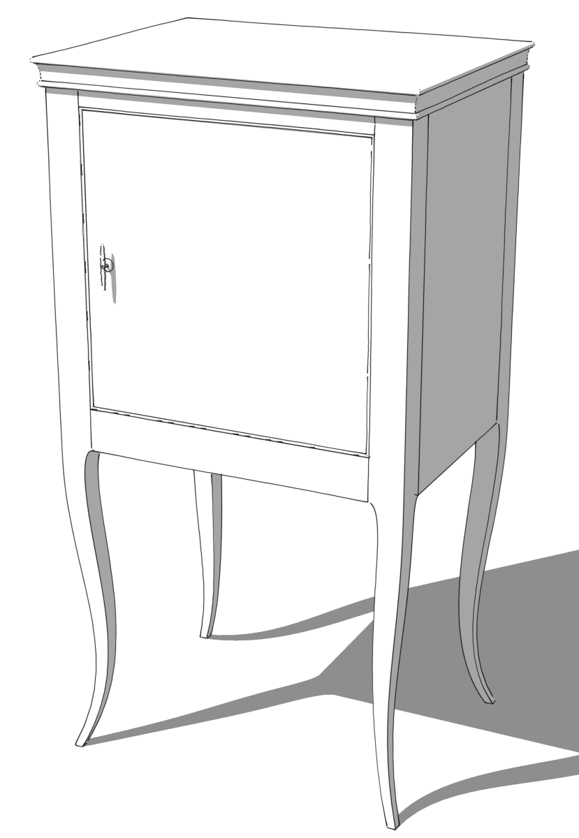
When all the waste is gone, you should be left with some shapely legs.
Clearly there are other applications for this sort of process besides just cabriole table legs so even if these legs aren’t your thing, you will probably find other places where you can use it.
–Dave





Comments
Dave,
This is a beautiful design. I am imagining how it will look with marquetry design on the front or top.
Would you take a look at this software for making inlay designs and let us know your thoughts?
The software called ImagePaint is here:
http://www.instructables.com/id/Laser-Marquetry-Inlays/
hi.I've been using free oak wood from pallets to make some really cool projects and selling them for some extra income. I've got thousands of woodworking plans to build. Here's where I got all my wordworking plans http://tinyurl.com/ntgfwjb
Brilliant job done!
Log in or create an account to post a comment.
Sign up Log in