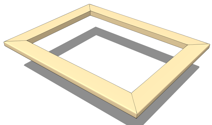
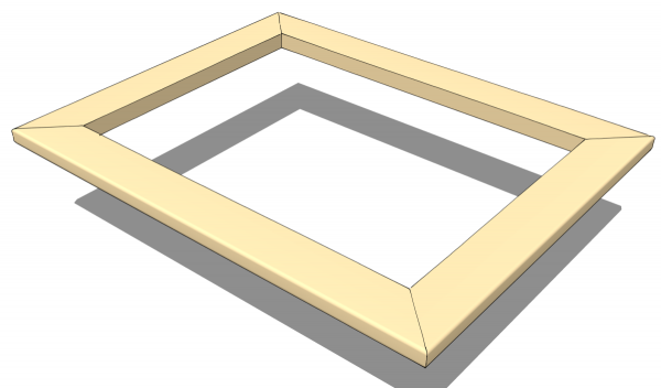
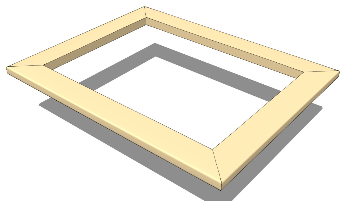
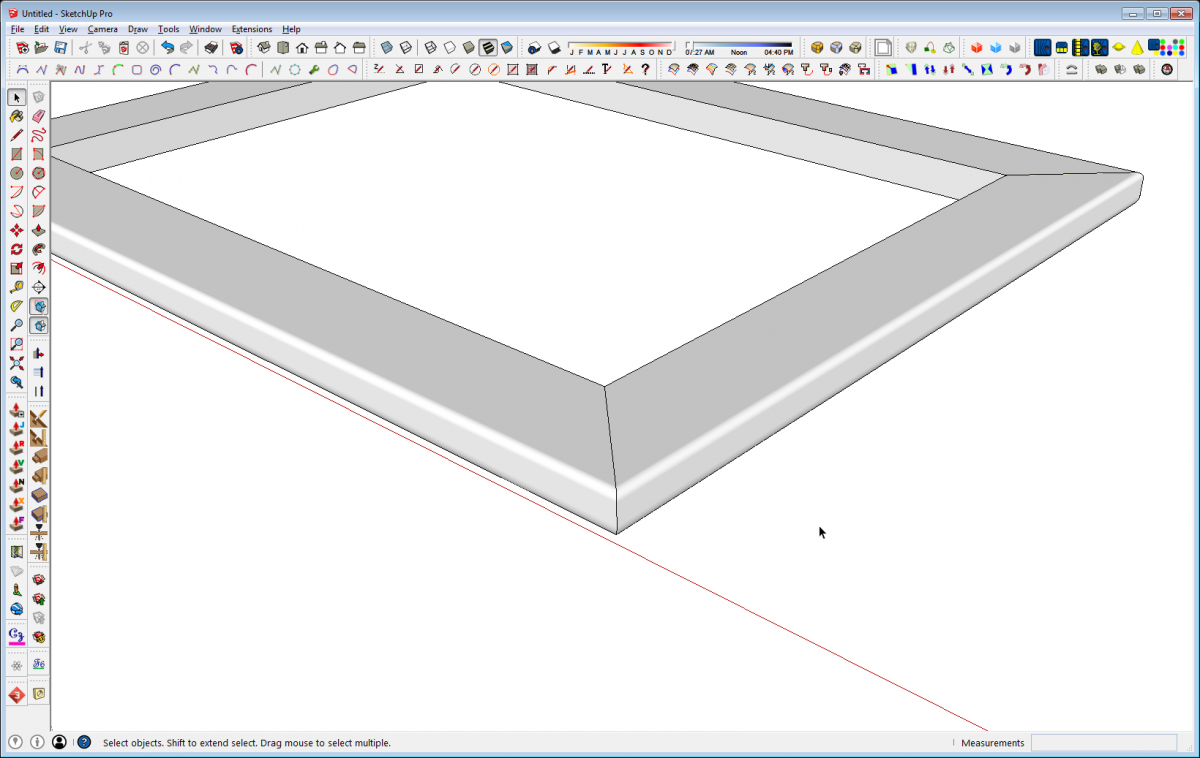
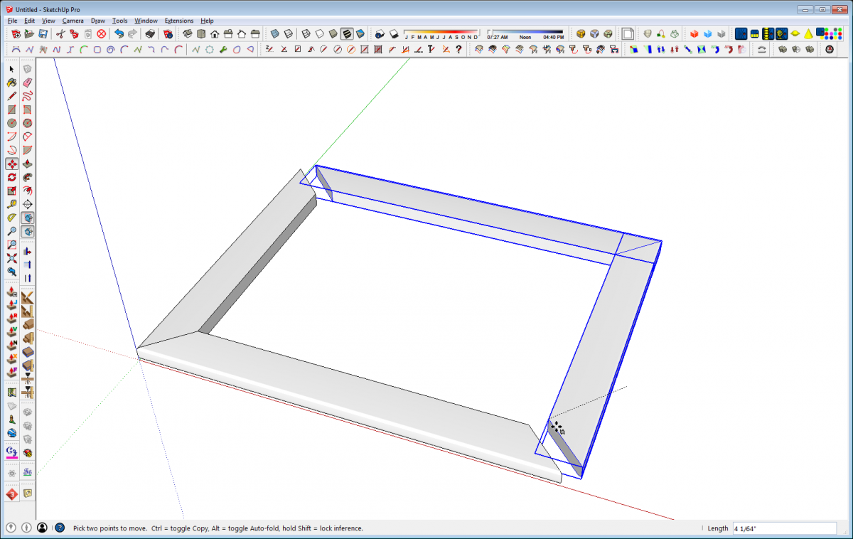
Last week I did a couple of on-line training sessions with a fellow woodworker. He’s just getting started with SketchUp and using a bedside table he’s planning to build as a subject for learning the program. He wanted to create what amounts to a mitered box for the base with a mitered frame on top of it. He first wanted to know how to draw the miters and then later he wanted to add radiused edges to the frame as in the image, above.
Here are a few different approaches to get to the same point. Although I’m showing the radiused edges that my student was after, the same approaches would apply to more complex shapes for things like crown moldings or mitered frame and panel doors.
Miter First
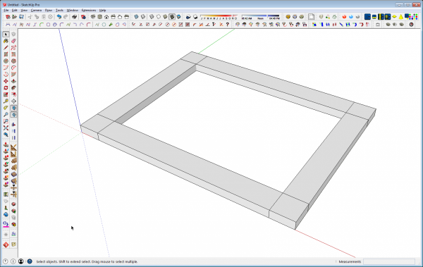
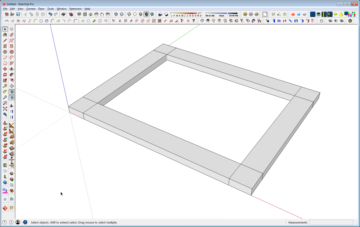
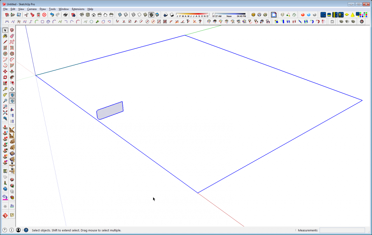
So here we are starting from a basic frame drawn with the components overlapping. This gives the parts at their full length. There are a couple of methods available to miter the ends. You could open the component for editing, draw diagonals on the top face from the inside corner to the outside and then use Push/Pull…
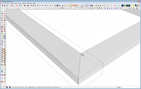
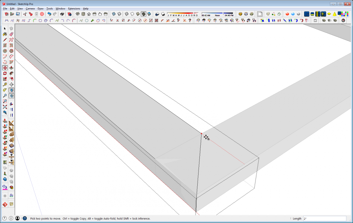
…or you could select the back vertical edge and use the Move tool to move it in to the inside corner.
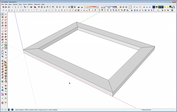
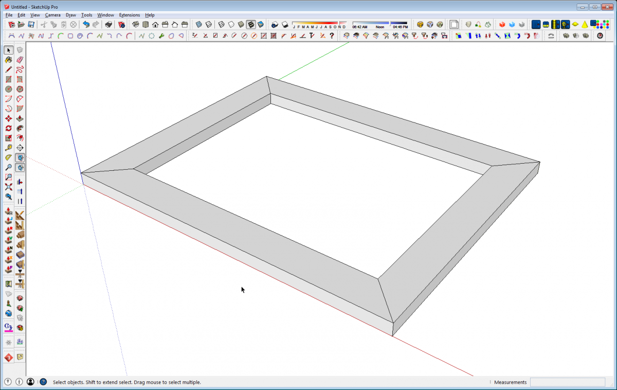
Repeat at the opposite end and on the neighboring component and you have a mitered frame. But now, putting a radius on the outside edges requires some setup to create profile “cutters” that can be used with Push/Pull. Then some intersections need to be created before erasing the waste.
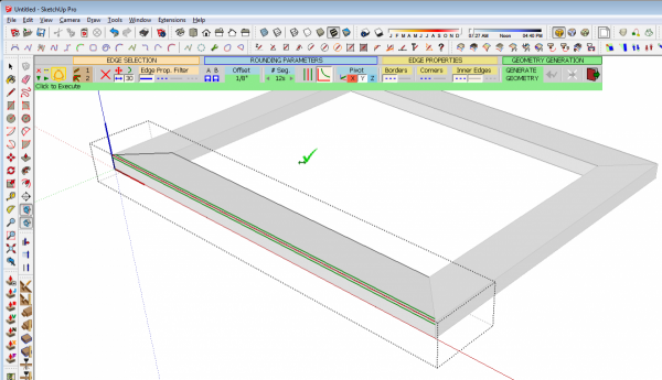
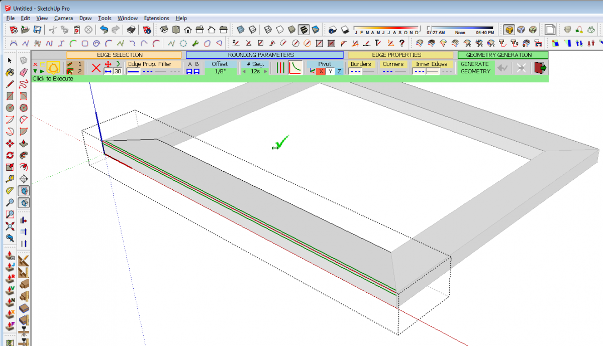
Although this won’t work for more complex shapes, for the rounded edges here, an alternative would be to do the heavy lifting with an extension called Round Corners which is available through the Plugin Store at Sketchucation. It works on selected edges and allows you to set the radius (called Offset in the extension) as desired. It takes care of the mitered ends of the radius automatically.
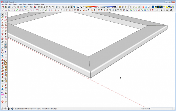
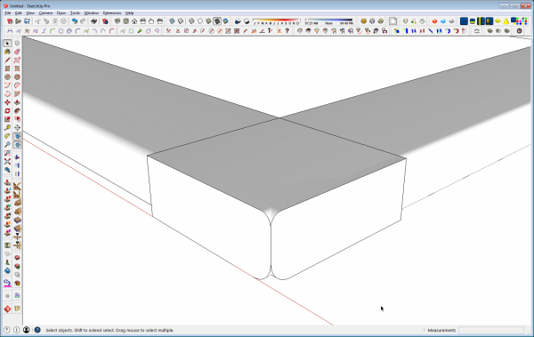
When you’ve finished running the plugin on each component the job is complete.
Profile First
Another approach would be to put the profile on the edges first and then cut the miters. The profiles are drawn on the square end and Push/Pull creates the profile.
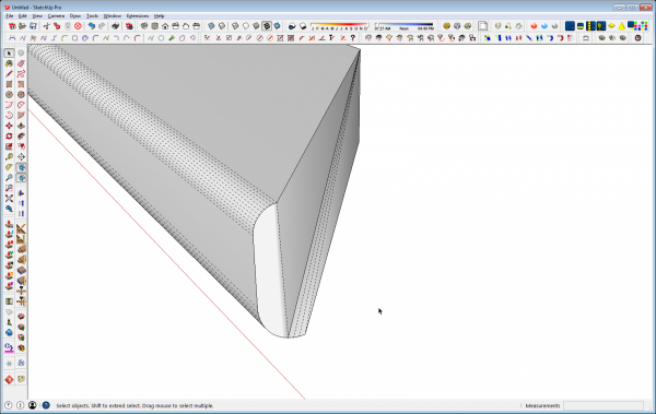
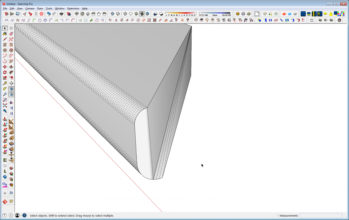
But how to cut the miters? Drawing the diagonal on the top face and using Push/Pull won’t work well because of the radiused edges and moving the inside corner in as I showed in the first method doesn’t work so well, either. In order to even move the edge in the correct direction, Autofold must be employed and it leaves very strange geometry.
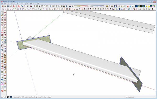
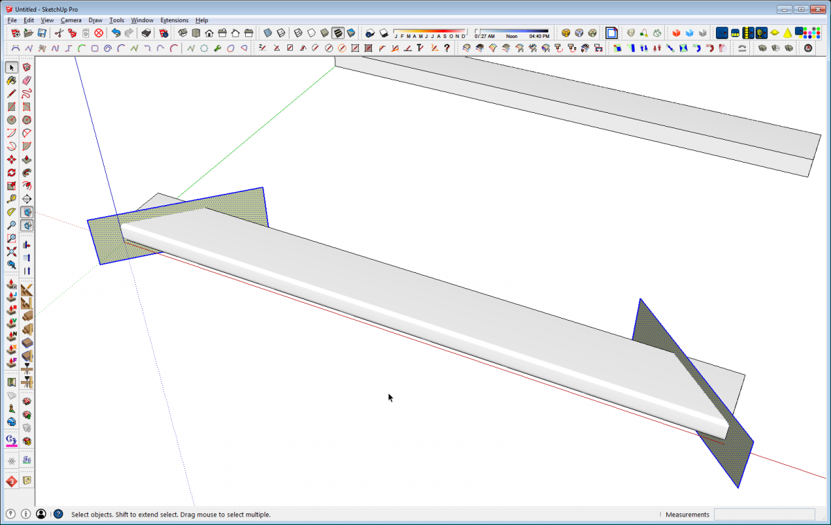
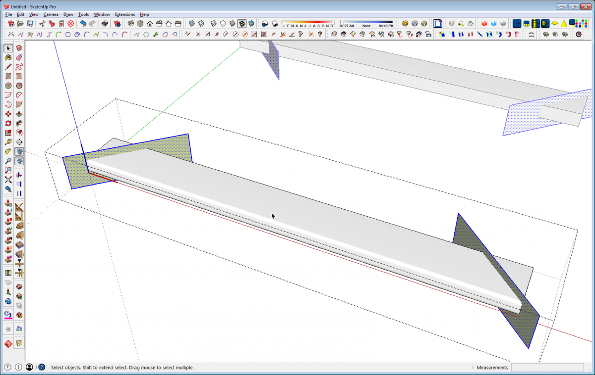
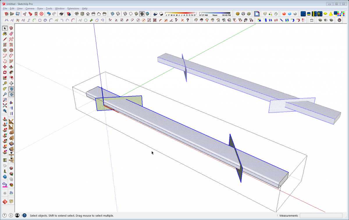
This is a job for cutting planes. Draw rectangles at the miter angle and intersect them with the frame member. Here, I’ve drawn the cutting planes outside the component. I prefer that to drawing them inside the component because I don’t need to wory about creating unwanted intersections.
With the cutting planes located where they are needed, I select them and use Edit>Cut (Ctrl+X on PC or Command-X on Mac) to cut them to the clipboard.
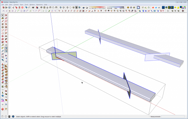
Then open the component for editing and use Edit>Paste in Place to paste the cutting planes into the component. For something like this, you might find it useful to use Push/Pull to extend the molding out well beyond the cutting plane. That’ll make it easier to select the waste for deletion.
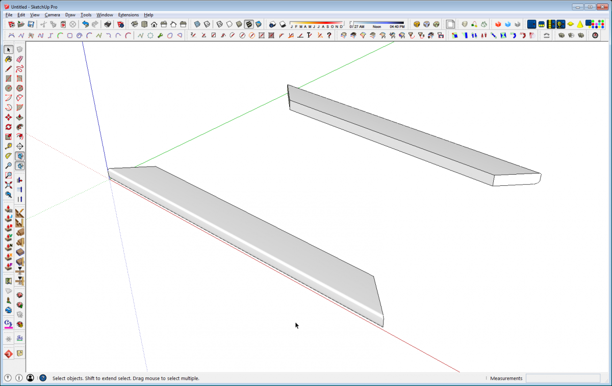
Select all of the geometry and use Intersect Faces>With Selection to create the intersections between the cutting plane faces and the faces of the molding. Then select and delete the waste of both the molding and the cutting planes.
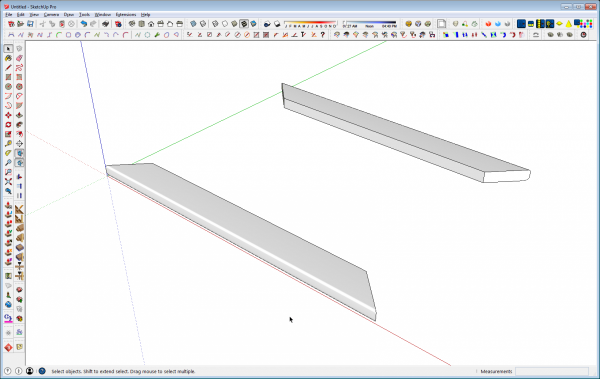
And Bob’s yer uncle: the miters are cut.
Note: it is important to put the cutting planes inside the component wrapper because you are not only cutting the molding but you are cutting the cutting plane as well. The face of the miter is actually what is left of the cutting plane after you delete its outside edges.
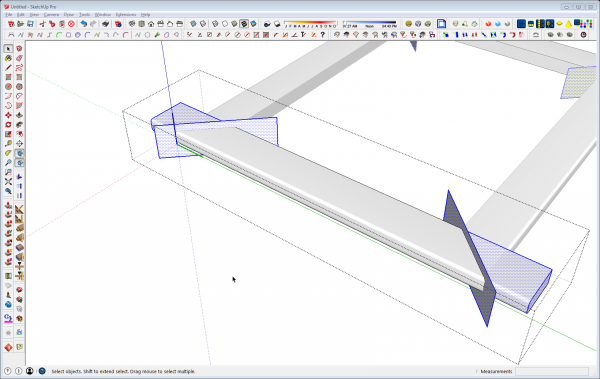
Repeat this on the neighboring component and the frame is complete. In the image above you can see how adding a bit of length to the molding makes it easier to select the waste for removal. After the intersections are made, drag a right to left selection box around the squared end of the molding. This will select that end and the surface of the molding up to the miter. You can make the selections for all that needs to be deleted and then hit the Delete key to get rid of it in one swell foop.
Follow Me
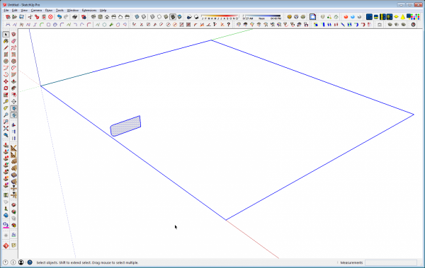
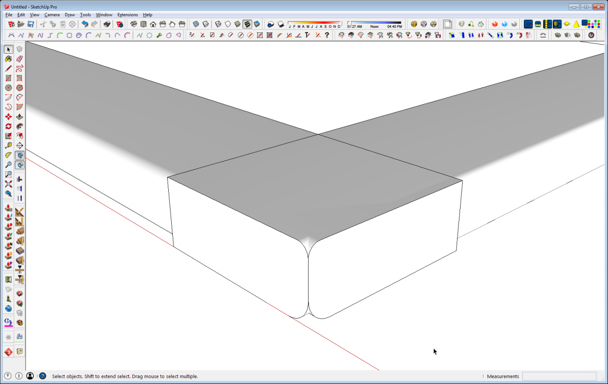
Another option is to start by drawing the entire frame as a single unit with Follow Me. Draw a profile and a path as above. Select the path edges, get the Follow Me tool and click on the profile.
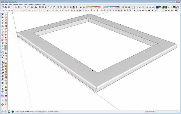
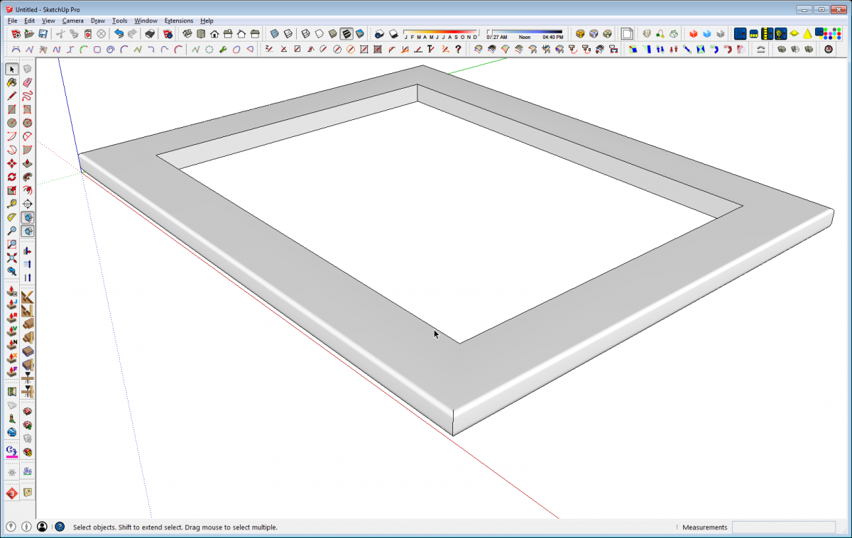
When the routine finishes, you are left with the frame but it’s as if it was cut out of a single wide board. For some applications, this might be a good place to stop. It may suit the purpose and there’d be no need to go any further.
But if you need the individual parts for exploded views or for a cut list, it is possible to divide the frame up.
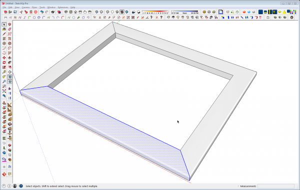
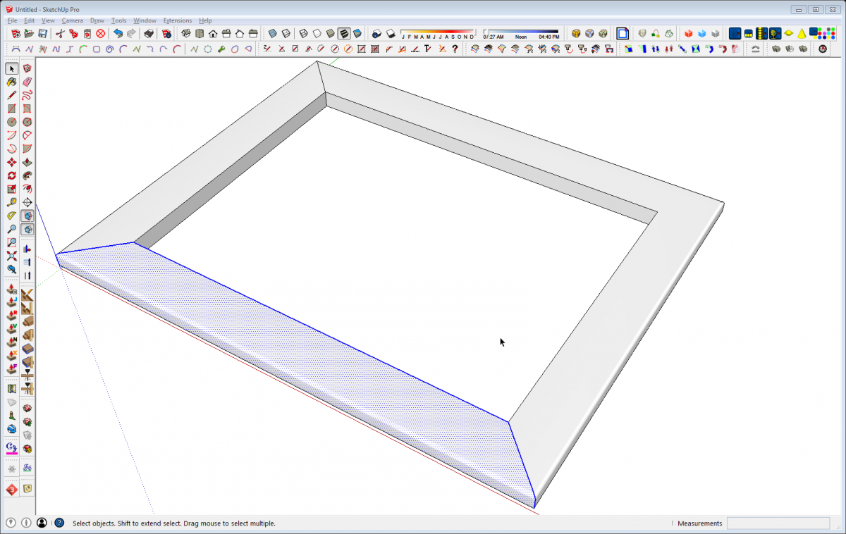
Start with the Line tool and draw in the diagonal lines as needed. Zoom in close to the outer corners to make sure your diagonal lines end at the right point. Make sure you draw them on both sides. You only need to draw these diagonals at three corners, though.
Use the Select tool to drag a left to right selection box around the geometry for one side of the frame as shown above. The hit G to create a component.
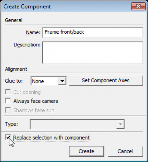
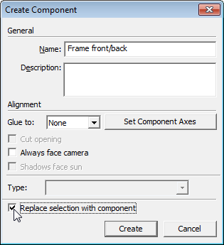
Give the component a name and be sure to tick the box for Replace selection with component. Usually when you are making a component, you are doing so with all of the connected geometry selected and so Replace selection… is automatically ticked. But when the selection set doesn’t contain all of the connected geometry, the box is not ticked. That’s actually a useful troubleshooting thing. If you making a component and that box isn’t already ticked, you’ll want to investigate why. Maybe you need to modify the selection set or maybe you need to modify the geometry.
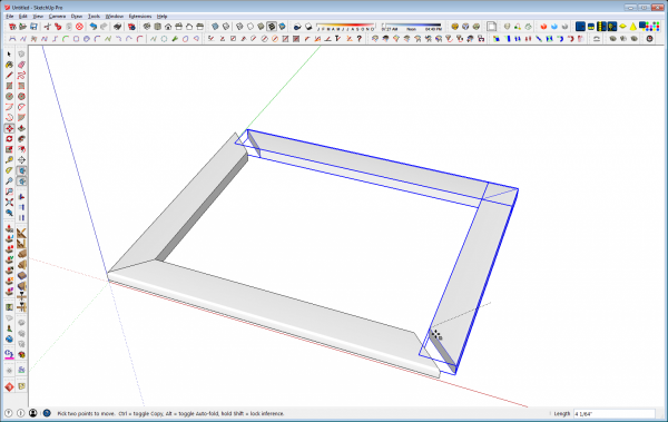
Repeat the selection for the neighboring side of the frame and make it a component. Then delete the geometry for the other two sides, copy the first two and use Flip Along to make the mirrored copies. In this case I selected and copied both sides at once using Move/Copy. Then I flipped the copies first in the red direction and then in the green direction. Finally, move the copies into place and the frame is complete.
Recycle and reuse
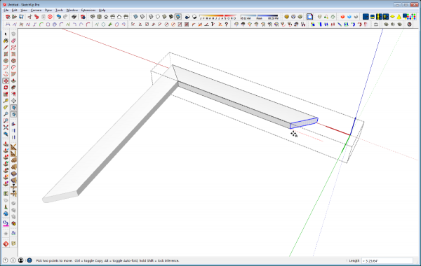
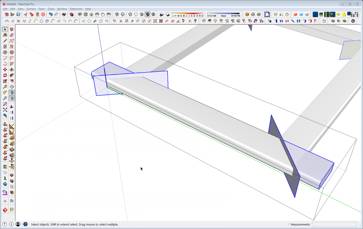
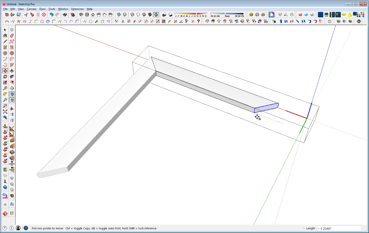
One other option would be to create a single component with the miters and profiles as needed and then use a copy of it to make the neighboring side. In the image above, I use Move/Copy to make a copy of the long side of the frame which I rotated and moved into position so the corners meet up correctly. Then, after making the copy unique, open it for editing, drag a left to right selection box around the end and use the Move tool to move the mitered end the required distance. Once you start the move in the right direction you can type in the length change.
This method would be especially useful if you have elements that you would use frequently in more than one project. For example, you might have a particular molding profile you use on various case pieces. Instead of drawing that molding and cutting the miters for every one of them, just make a component with the miters and save it for future use. Then insert it into your current model and adjust the length as needed.
As with almost everything in SketchUp as well as in woodworking, there’s generally more than one way to get to the destination. Some may be easier than others but depending on the application, one method might make more sense than another. Having them all in your bag of tricks and being able to select the best one for the job goes a long way to making the job easier.
–Dave



Comments
I've used Sketchup myself several times and coping and pasting was what I did most often. However, now I draw everything by hand as it's easier for me. That and the fact that the furniture I come up with isn't very complex.
Your tutorial looks great. How many hours did it take you to finish it?
"Your tutorial looks great. How many hours did it take you to finish it?
It didn't take that long. Maybe an hour and a half for this one but I type kinda slow.
Log in or create an account to post a comment.
Sign up Log in