The Mortise & Tenon joint is probably used more than any other in woodwork, and there are a great number of varieties. Perhaps the most commonest application of the joint is in making door and other frames. But there other applications involving Wedged Through-Tenon, Fox Wedging, Drawer Rail Tenons, Bare-faced Tenons, Corner Leg and Rail Joints, Molding Bars, Drawer Rail, Pinned Mortise & Tenon, etc. So it is likely that if you are a woodworker you are encountering one type or another of these joints on a regular basis.
Then it follows – if you are a beginner in SketchUp, you’ll quickly be faced with “making” a mortise & tenon joint. In the following video, I provide a beginning exercise in making this joint, and it ends with preparing the dimensioned drawing that would be used in the shop.
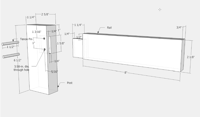
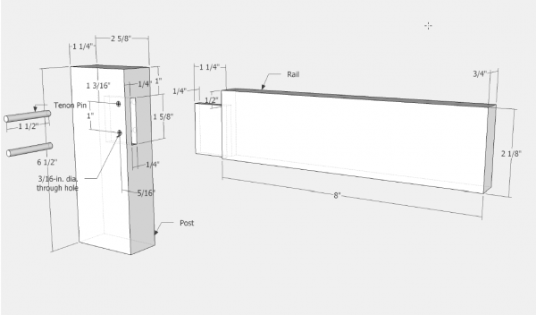
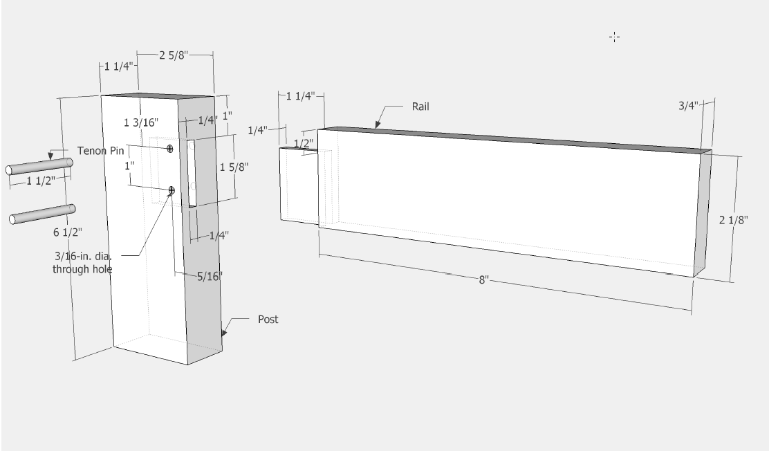
Here is the final dimensioned drawing, that can be used as you develop the model in SketchUp.
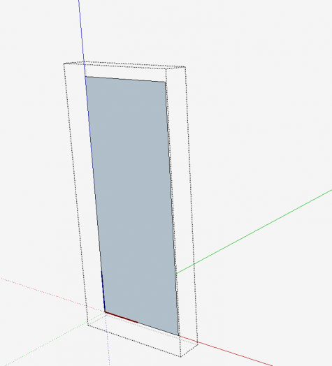
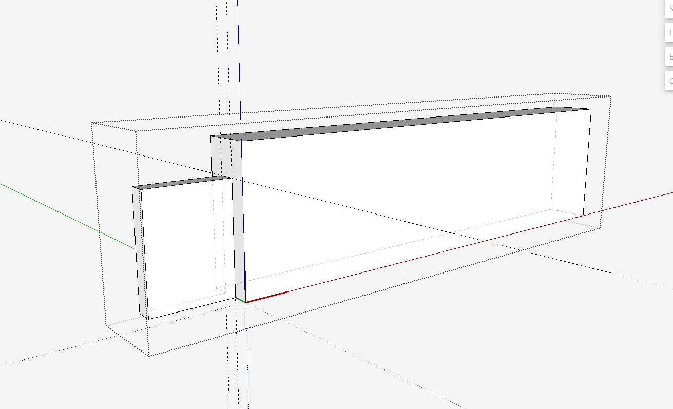
Start the modeling by making the Post that is 6 1/2-in. long, 2 5/8-in. wide and 1 1/4-in. thick.
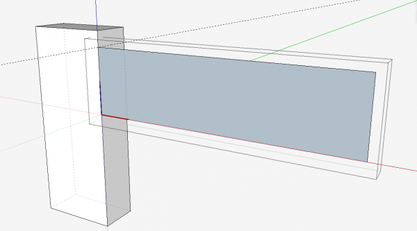
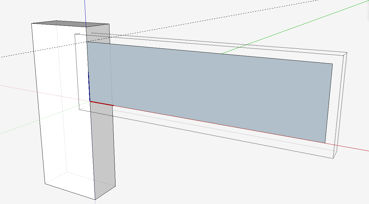
Now create the Rail… 9 1/4-in. long, 2 1/8-in. wide, and 3/4-in. thick. It is important that you make the rail in its actual position on the Post. Obviously, it can be created separated from the Post, but you should get in the habit of creating components at their final position in the assembly. Following this rule will make your modeling more efficient and accurate.
Make a copy of the Rail, place it down the red axis, and on that copy create the tenon.
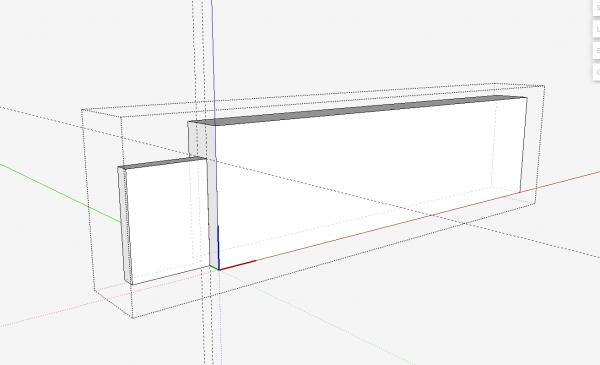
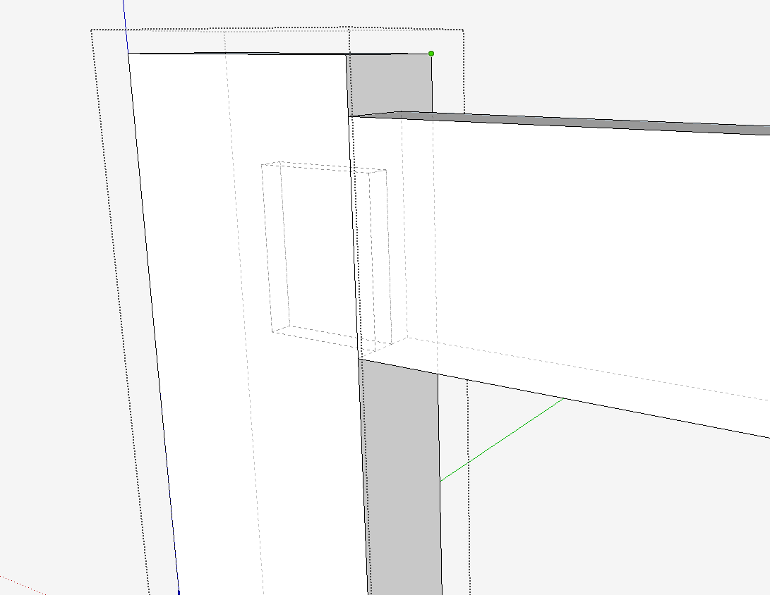
Delete the copied Rail, and return to the assembly. Open the Post for edit, and set the Style to X-ray. With the Line Tool, trace over the boundary of the tenon as it protrudes through the edge face of the Post. Then with the Push Pull Tool, cut the mortise.
If you find it difficult to see the Rail’s tenon in the X-ray view, go to Window/Model Info/Components, and move the slider bars to Darker.
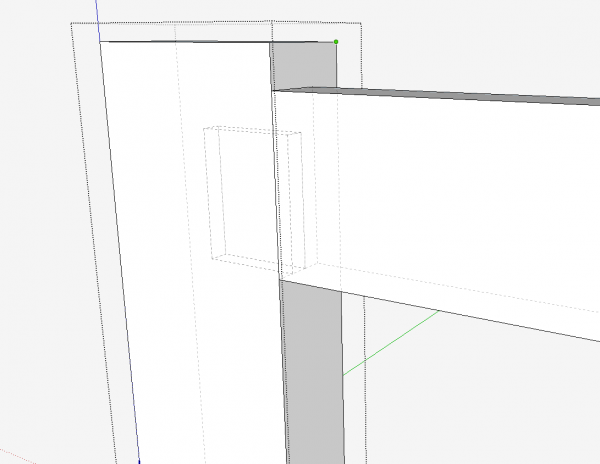
The last steps are creating the Tenon Pins and their associated sockets. Copy the two components and move them down the red axis. With the Move Tool, pull the Rail out of the mortise. In this exploded view, place dimensions that you will need in the shop.
Here is the video.
Tim
@KillenWOOD




Comments
This was very helpful. But as I followed these instructions to trace the tenon as it enters the post to make the mortise, when I copied and flipped the post for the other end of the rail, the mortise is in the wrong place. So is there another way to do this so the mortise is in the right place, or do you not trace the tenon until you already moved and flipped the post?
Jan, assuming you created the first post in the same orientation as I show, and you flipped the copy of the post along the red axis, then the mortise will be in its proper location at the other end of the rail.
You can send me your file and I should be able to tell where things went awry.
Tim
I thought I did, but I was able to clip out the extra mortise in the post component and that did it for the others. I will watch that next time.
But now, I have another problem. I have drawn the table completely in components and assembled it. That includes all the joinery. But I don't like the proportions and want to reduce the length of the side rails by 2 inches. This is complicated by the fact that there two side rails on each end-- narrow upper and lower rails. They are each different components since they are not the same width. I would rather not have to redraw the tenon on the ends, but if I edit both components) and select just the rails without the tenons, copy and use line draw and push/pull to shorten them them by two inches, this doesn't result in reducing the length of the components that are still in the drawing. It results in a weird component that includes the old rail and the new rail that can't be placed anywhere. I'm obviously missing a step.
I tried venturing into using scale, but that didn't work. Suggestions?.
By the way, it is really nice that you respond to questions by beginners. I would have thought this would be a common issue, but I didn't find anything that seemed relevant just to reducing the length of a component after it had been assembled. Yet it seems that to change proportions should be one of the things it would be easy to to in Sketchup.
Jan, to change the length of a rail equipped with tenons, you should use the Move Tool. Open the rail for editing, then with the Select Tool draw a left to right box around the end of the rail including the tenon. Then select the Move Tool and move on the appropriate axis and type the desired distance. This will result in a shortened rail while keeping the tenon.
Tim
Bingo. Thank you. I had been selecting the entire component rather than just the end. I guess the answer was in your original lesson here about flipping the tenon to the other end of the board.
In this lesson and in your book, you explode the drawing by moving the individual components apart with the move tool. What is the function of the "explode" option? Google makes it sound like you could explode the entire assembly at once although I guess you'd need to make your assembled drawing a component first. Is that right and, if so, why do you recommend moving the parts piecemeal?
Jan, if I make take the liberty of answering... The Explode command removes the "wrappers" from the components and groups in your model. That is NOT what you want if you wish to make and exploded view because it will allow the loose geometry to fuse together.
There are a couple of plugins out there that can move components to create exploded views. I've used both but find it's easier to control exactly where the components get placed if I make the exploded view manually.
-Dave
By the way, at least when I make exploded views I start out with deliberate selection sets which get moved in a certain direction. Then I change the selection set and move again. It really takes very little time and I can easily determine exactly where each part needs to go. -D
Thanks for the explanation.
Jan, for furniture, I typically make the entire assembly a component, inside of which are all the individual piece components. I do this because I use the assembly in making the orthographic scene, front,side, and top. This way any change to the assembly also changes the orthographic.
Then when I make the exploded scene I need to explode the the copy of the assembly first, before pulling apart the individual components.
In the case of this mortise and tenon joint, I did not make an overall assembly component, so there is no need to explode when doing the exploded scene.
Tim
Log in or create an account to post a comment.
Sign up Log in