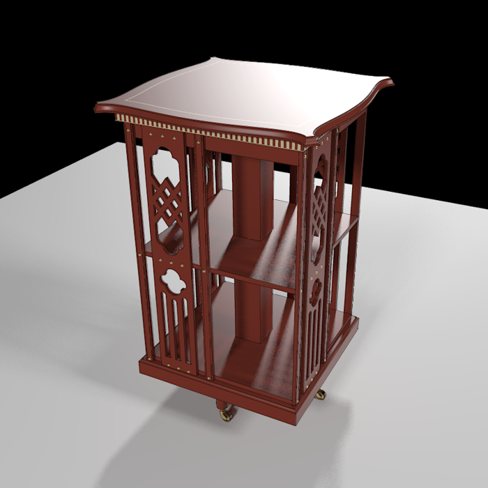
I had an opportunity recently to talk with some British woodworkers about using SketchUp and a question came up regarding the order of operations specifically regarding putting a profile on the edges of a table top. For many tasks in SketchUp, the order you do things in can be switched up but often doing them one way can result in less work than other methods. And sometimes it’s six of one and half a dozen of the other.
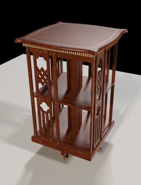
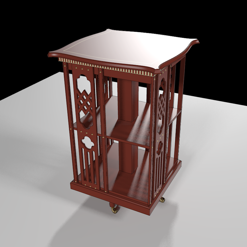
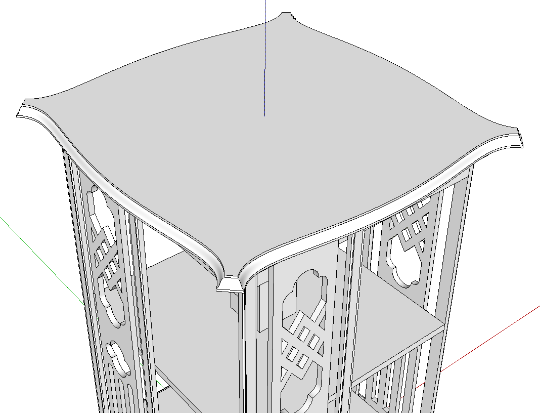
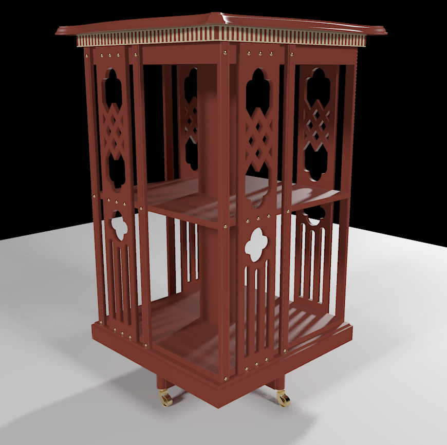
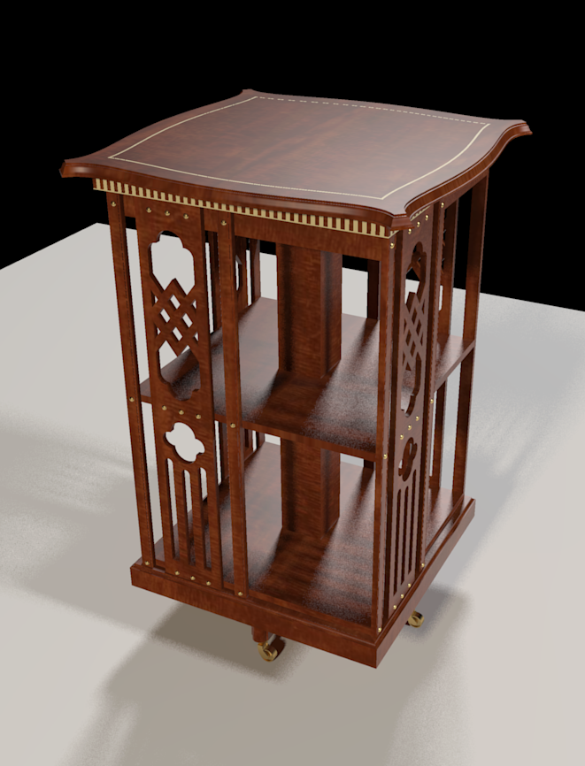
I drew this little Edwardian-period revolving bookcase to provide some examples. This one project could provide several case studies on this subject. I’m going to show one way to draw the top.
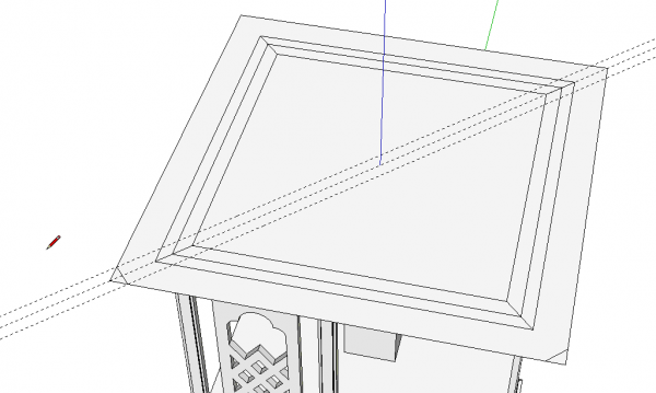
As I wrote, there are several ways to approach this. You could do something more like you might do in the shop and cut the top to size, then add the curves between the corners and finally route the profile. This time, I opted to change it up a little.
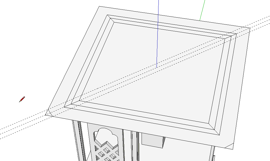
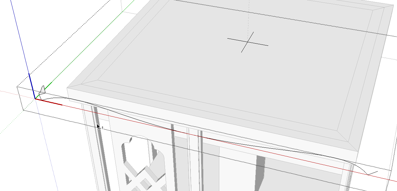
I started with a square to know I have the overall top sized correctly. I laid out for the mitered corners on just two of them.
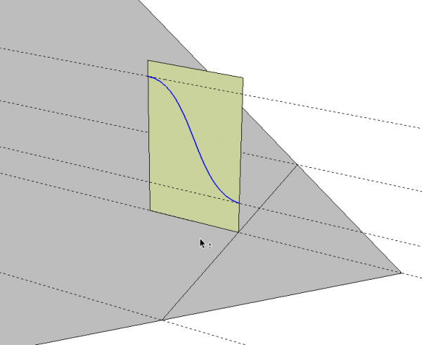
I drew the profile for the edge at one corner. The profile is drawn at the midpoint of that mitered edge. You’ll see how that works out shortly.
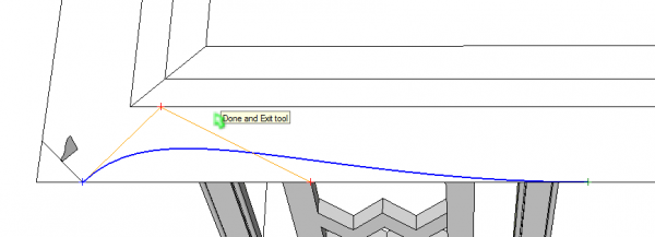
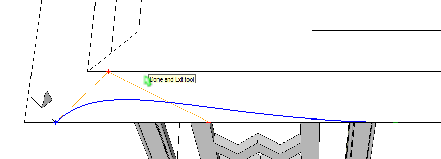
Then I used the Bezier Curve tool to draw the curve. Since the curve is symmetrical across the top, I only drew half of the curve. When you draw a curve with the Bezier Spline tool, don’t agonize over getting the curve shape correct the first time. Just get it in and then adjust it by moving the little red + symbols.
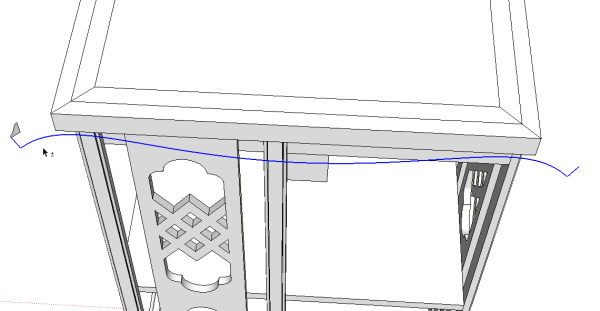
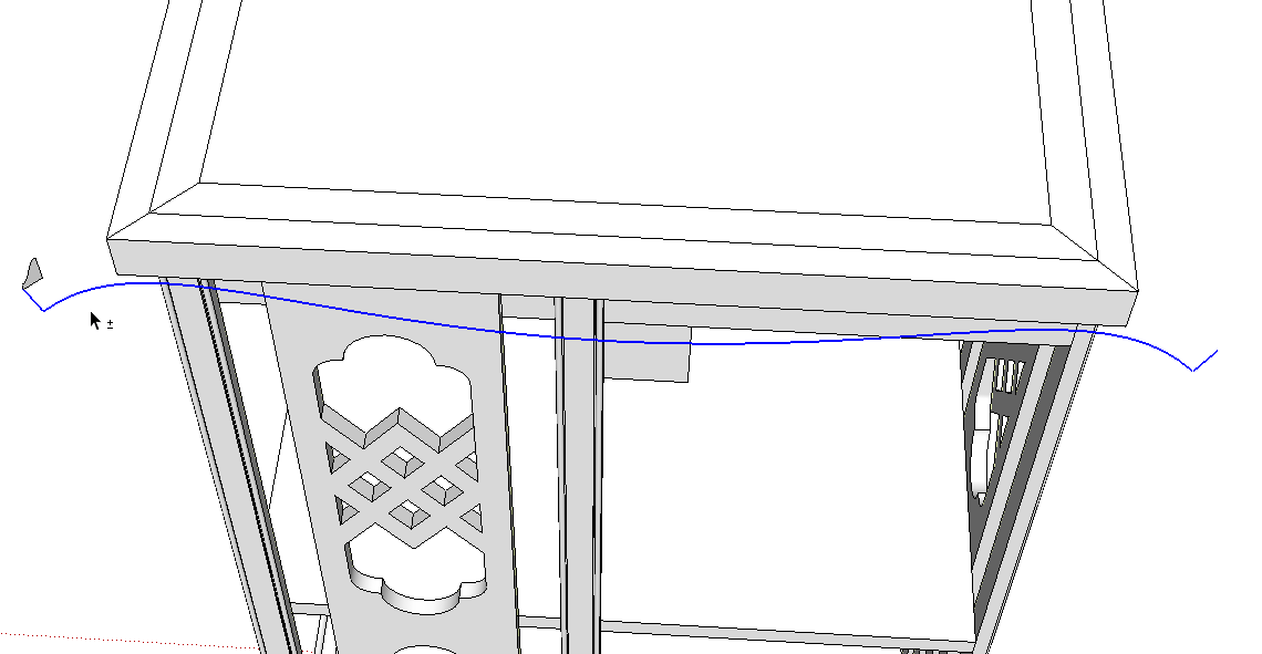
After getting the curve drawn, use Move/Copy and copy it toward the opposite side. I copied it in the red direction past the right hand corner of the top. Then I mirrored it using the Scale tool and moved it into place so it connected to the miter line drawn on the right front corner. That miter line get split in half by drawing a temporary line from its midpoint and then erasing the unneeded part.
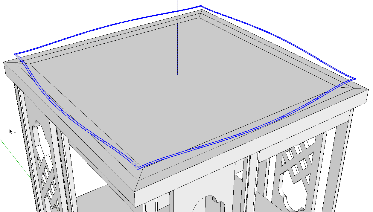
I deleted the rest of the square leaving me with the curve shown in blue which will be the path for Follow Me and the profile over on the left.
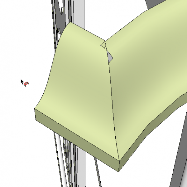
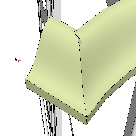
Now it’s time to run Follow Me. Well, almost. In the case of the profile I drew, running Follow Me at the normal size of the profile and path results in some small holes at the corners. This wouldn’t happen with every profile and path so might be worth giving it a try. If you do get holes you use my favorite trick.
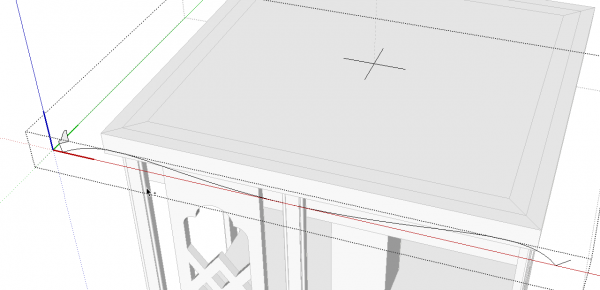
I selected the path and profile and made a component. In this case, I also added cross hairs at the cetner of the top. They’ll get deleted later.
After creating the component, I used Move/Copy and made a copy of this component. Be sure to do that with the component showing the blue bounding box. that indicates the component is not open for editing. Then scale the copy up by a factor of 100 or 1000. Open that component for editing and run Follow Me.
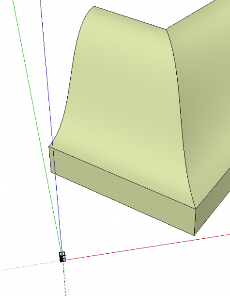
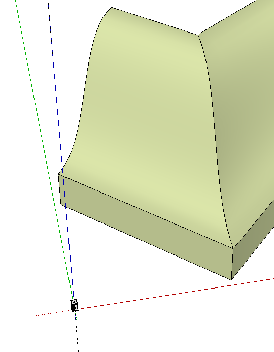
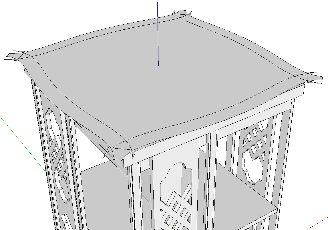
Here is a close up of the corner of the large copy of the component. You can see the corner closed up nicely. You can also see the full sized model at the origin.
The faces are reversed in the extrusion as indicated by the green color which is my back face color. It’s a good idea to correct face orientation as it happens so I reversed the faces on this geometry. Then I erased the flat bottom and inside faces leaving just the profile as a shell.
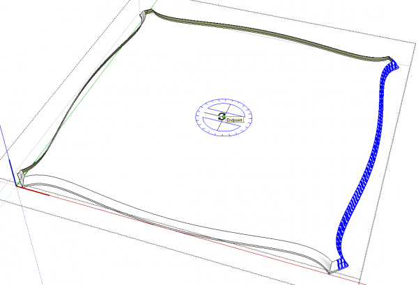
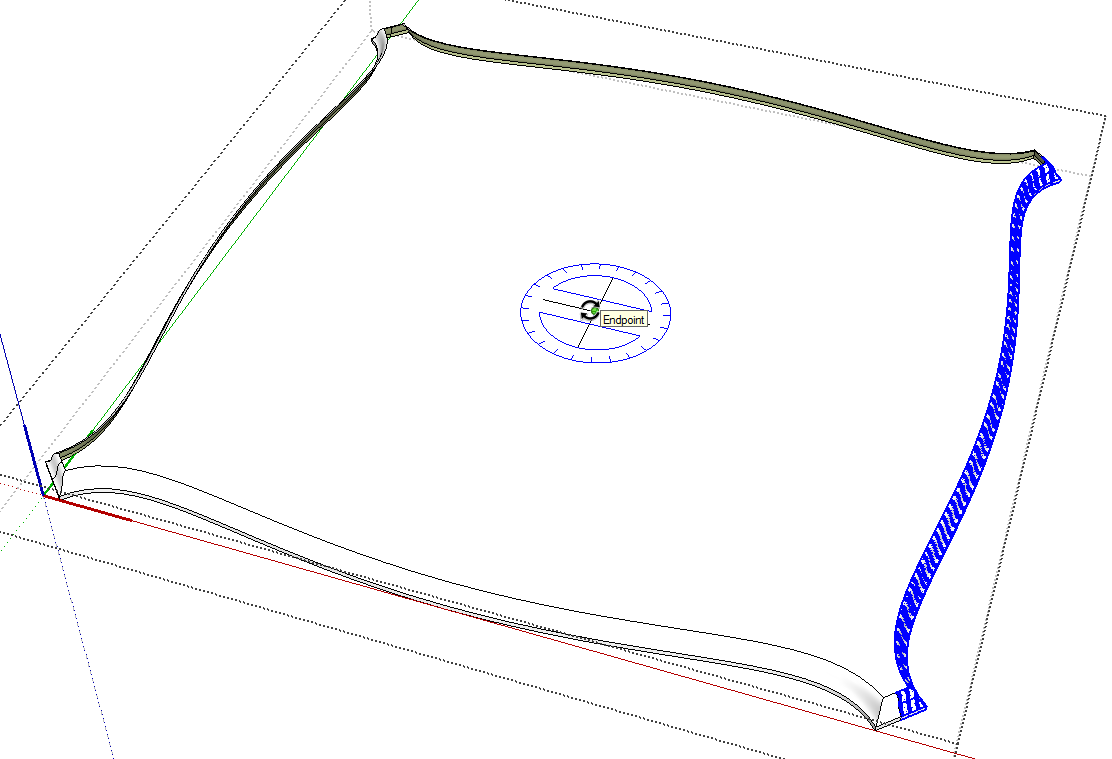
Next, I selected the profiled edge and use Rotate/Copy to create the other three edges. As with the Move tool, hitting Ctrl on the PC or Option on the Mac invokes the copy function. Rotate the first copy and type 90, hit enter and immediately hit *3 or x3 or even 3x and hit Enter again.
At this stage theres no top or bottom. Get the line tool and trace an edge along the top and another on the bottom to generate the needed faces.
After the faces are complete, click with Select outside the component to close it. Or hit Esc to do the same thing. Then delete the giant copy of the component and return to the model with Zoom Extents.
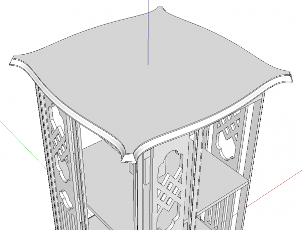
This profile has a small vertical section at the top. The easiest way to create that is to use Push/Pull to pull the top face up.
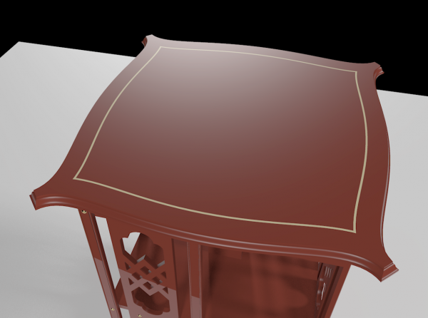
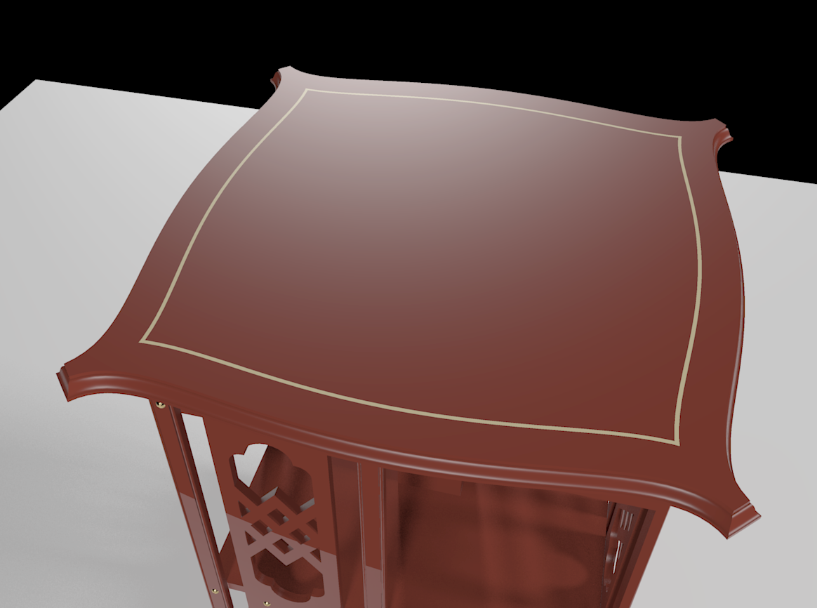
The top for this piece has a thin stringing set in from the edges. To add that detail, I used Offset but due to the shape of the top, Offset will create some unwanted geometry. To avoid create unwanted intersections between the edges of the top and the offset edges, I decided to create the stringing outside the top component.
I opened the top component for editing and with Select, double clicked on the top face to select the face and its edges. I copied the selection with Edit>Copy (Ctrl+C or Command-C) and then I closed the top component by hitting Esc. Next, I used Edit>Paste in place to put the copied face back out into the model.
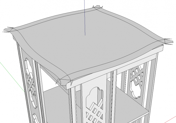
Selected the face and get the Offset tool. Click on the edge and drag in the required distance. You can see the excess geometry at the corners. This can all be erased. Note, I temporarily hid the top to get it out of the way.
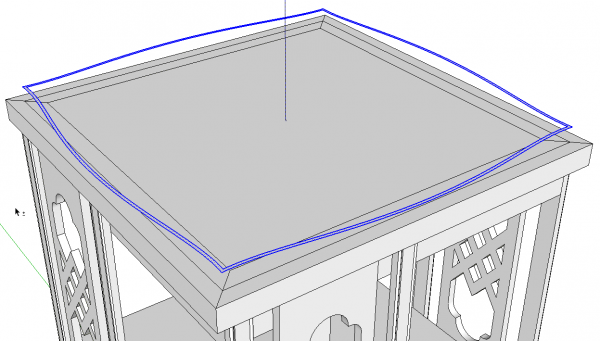
After the excess geometry is cleaned up, run Offset again to create the width of the stringing. Delete the inner face leaving just the stringing.
There isn’t much point in creating the excess geometry that you’d get from making the stringin 3D. I selected it and used Edit>Cut to cut it to the clipboard. Then I unhid the top, opened it for editing and used Edit>Paste in place to paste the stringing into the top. This results in separating the top so different materials can be applied for the top and the stringing.
It looks like a lot of steps but it goes pretty fast when you get to doing it.
As you are drawing in SketchUp, you might find it useful to experiment with different approaches to drawing things. Maybe you’ll find a way that works better for you and results in less work.
–Dave



Log in or create an account to post a comment.
Sign up Log in