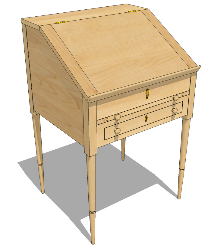
A couple of weeks ago I had an e-mail from a long time reader of the blog regarding the axes in SketchUp. And then, just last week the topic came up during an online SketchUp workshop I gave to a group of woodworkers so it seems like a good topic for the blog.
Model Axes
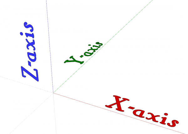
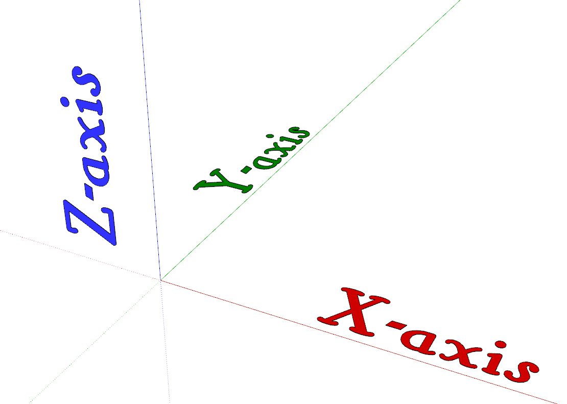
When you first open SketchUp, you’ll see the red, green, and blue axis lines which are used to define the 3D space represented on the 2D screen. These axes intersect at the model space origin (0,0,0) with red representing the X-axis, green the Y-axis and blue, the Z-axis. The solid lines run off in the positive direction from the origin.
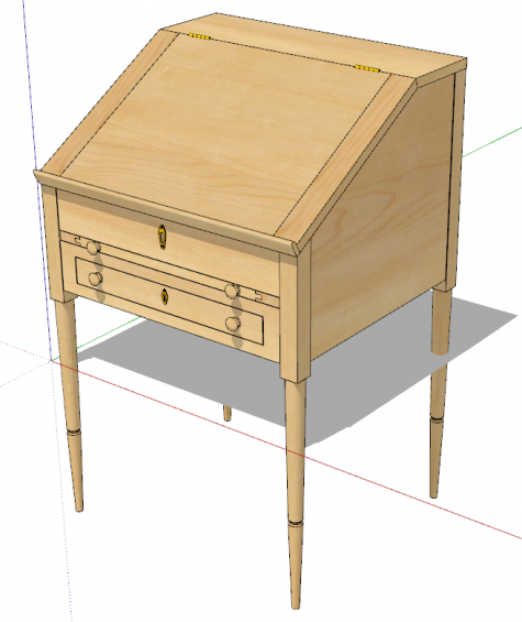
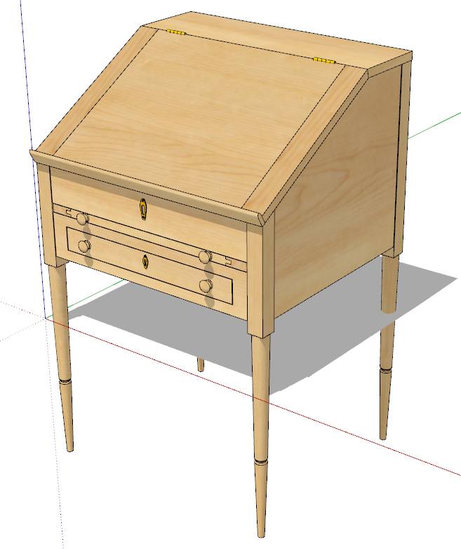
Also, by default, the red and green axes lie on the ground plane and of course, the blue axis goes up. Generally, it’s a good idea to draw your models so they are standing on top of the ground plane rather than extending below it. This can make it easier to work with your models and if you use shadows when creating image exports, you’ll get expected results. In the image below, I moved the model down and you can see what happens to the shadows.
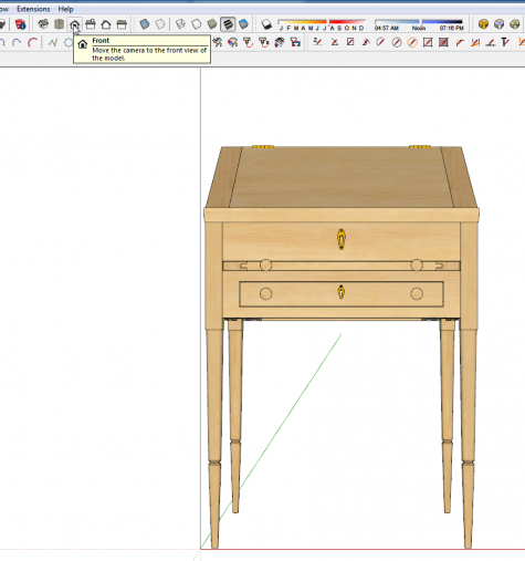
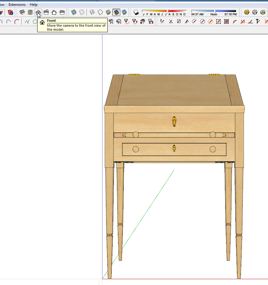
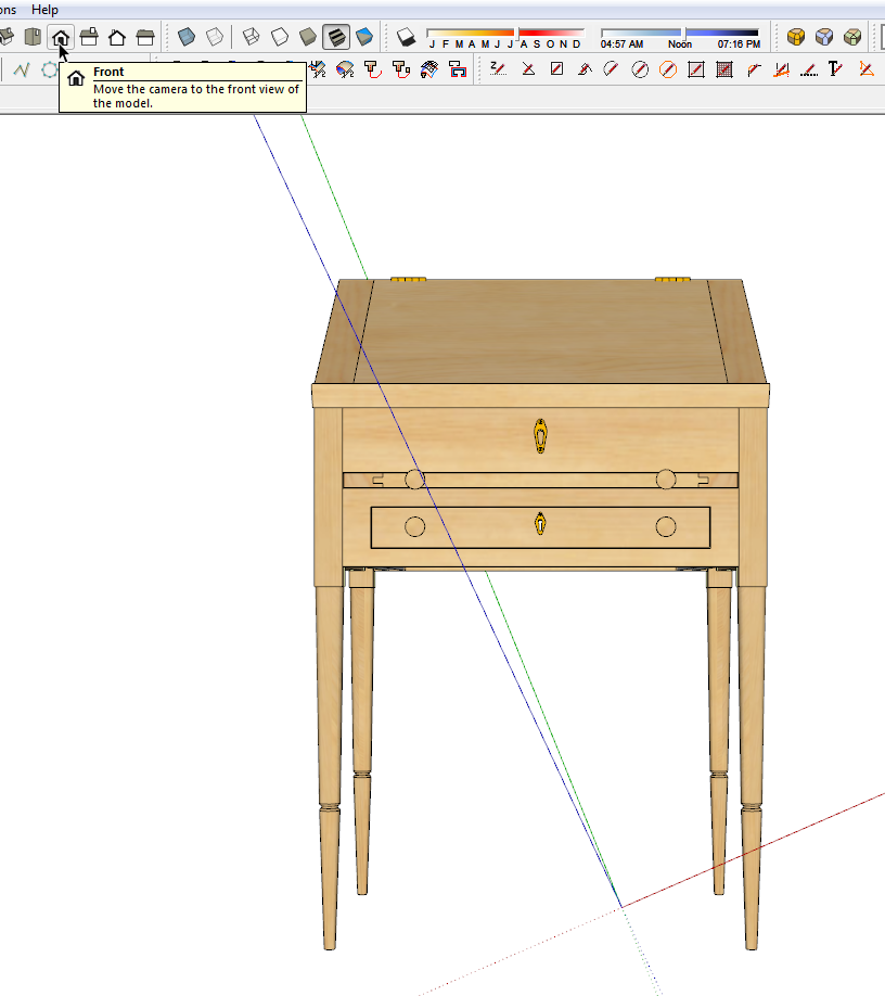
By default, the axes are aligned so that with the standard front view, the red axis runs from left to right across the screen and the sold (positive direction) green axis runs back into the screen. The other standard views which can be accessed through either the Camera menu or the Views toolbar are set up similarly.
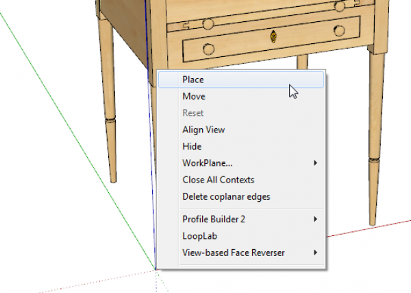
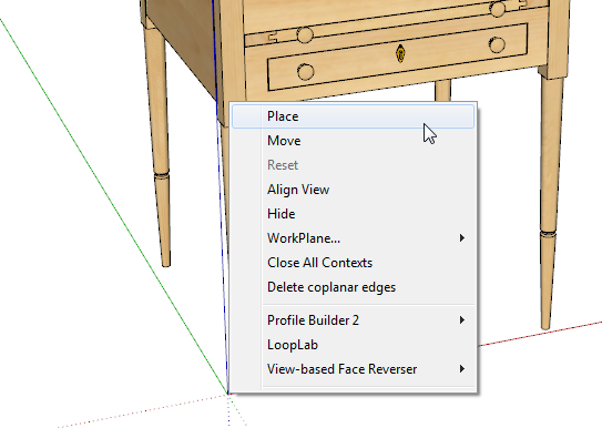
It is possible to reorient the axes lines which some users find useful when drawing things that won’t align naturally with the default axis orientation. To do that, right click on the origin and choose Place. Then you can click to set the origin, click again to set the red direction and one more click to set the green direction.
In the next image I’ve moved the axes. Note that changing the location and orientation of the axes does not change the standard views nor the location of the ground plane. The drawing tools as well as Move and Rotate will orient related to the axis lines. So you can reorient the axes to make it easier to draw lines at an angle.
I rarely ever change the axes location of orientation when I’m modeling. Even for drawing parts at angles to the axes, I find it just as easy to layout guidelines at the required angles or use existing parts of the model for reference.
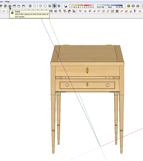
If you’re moving the axes, keep track of what you’ve done. I’ve seen a number of cases where users had inadvertently moved the axes and then drew at least part of their model based on those moved axes. In all cases it caused them problems. I only saw their models because they asked me to troubleshoot for them. Sometimes it’s easier to start over than it is to fix the model.
Resetting the axes is done by right clicking on the origin and choosing Reset from the Context menu.
Component Axes
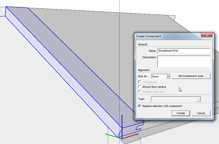
Groups and components get their own origin and axes when they are created. Normally the axes will be parallel to the model axes. You can see the axis location and orientation when you are creating the component, below. You won’t see this when making groups because there’s not really any user control over their orientation.
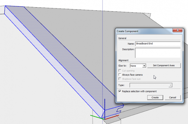
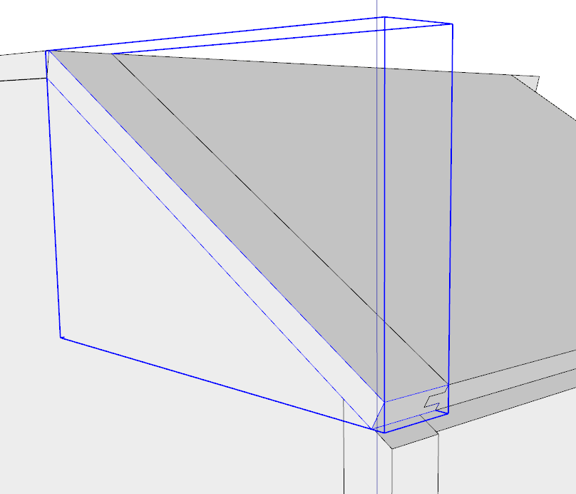
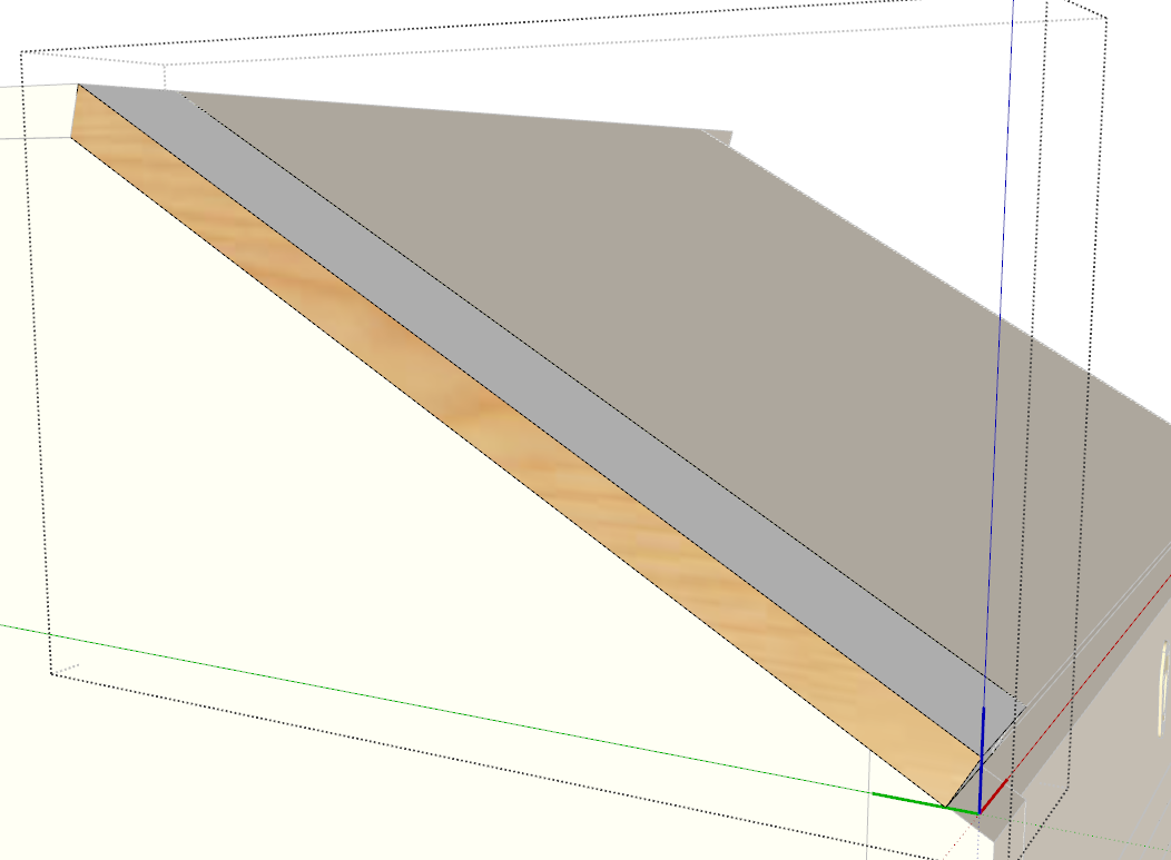
The orientation of the component or group axes sets the bounding box. If you draw parts in situ as I do, this can result in a very large bounding box when the geometry is drawn at an angle as in this breadboard end.
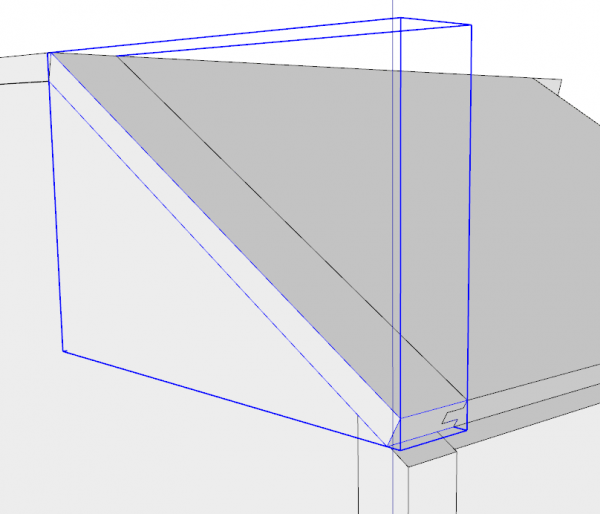
On its own, that’s not really a problem but it can make it difficult to apply materials to the faces correctly. For example the wood grain material here gets applied parallel to the green axis.
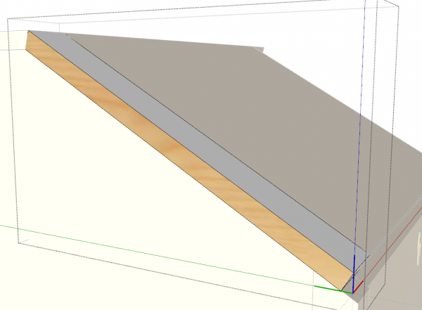
Aother issue comes into play if you need to make a cut list. The CutList extension uses the dimensions of the bounding box as the size of the part. With the bounding box oriented as above, the cut list would report the part size as being much larger than it needs to be.
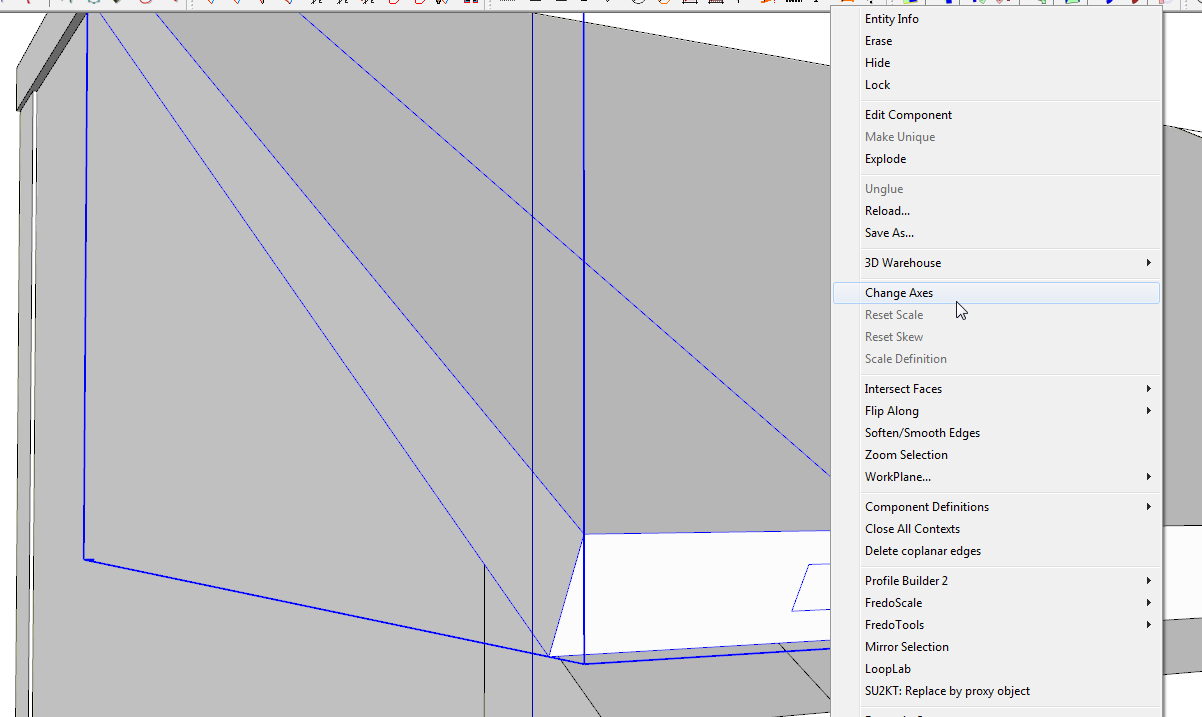
It is easy to set the axes so they are oriented appropriately for the geometry in the component. You can do this when creating the component in the first place by clicking on the Set Component Axes button or you can modify them after the component is created. To do that, right click on the component and choose Change Axes.
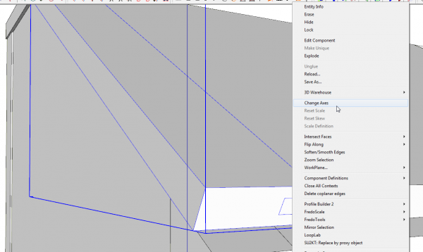
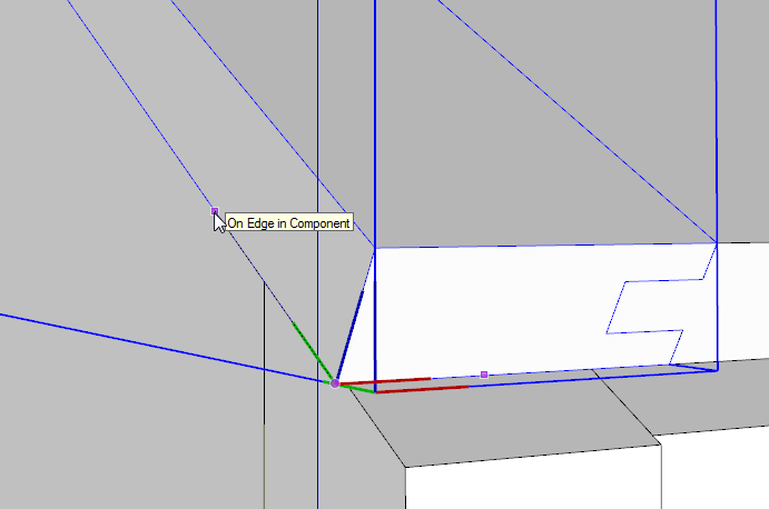
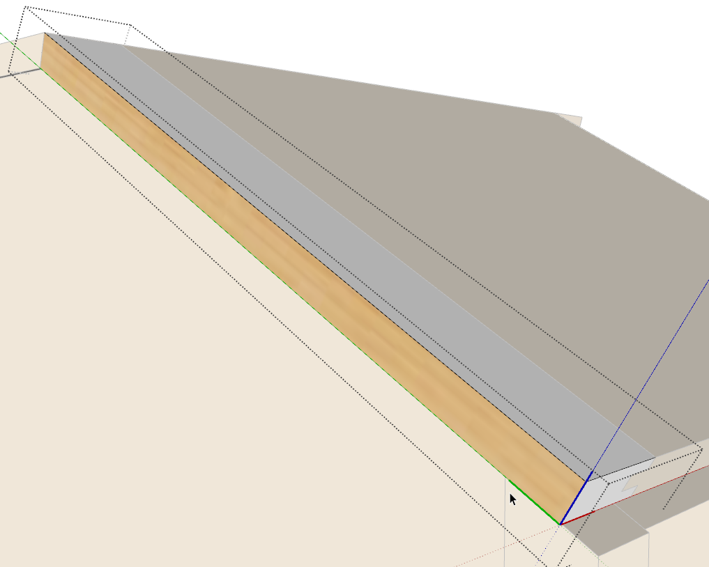
Then click to set the origin, drag out and click to set the red axis and then do the same for the green axis. The blue one will take care of itself.
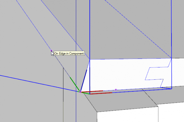
After you set the green axis the bounding box will change the alignment. Now that the axes are aligned with the edges of the part, a cut list would report the correct dimensions and it is easy to apply the material with the correct alignment.
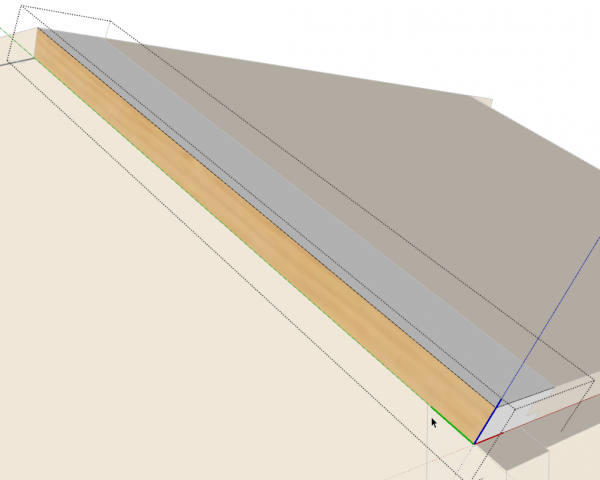
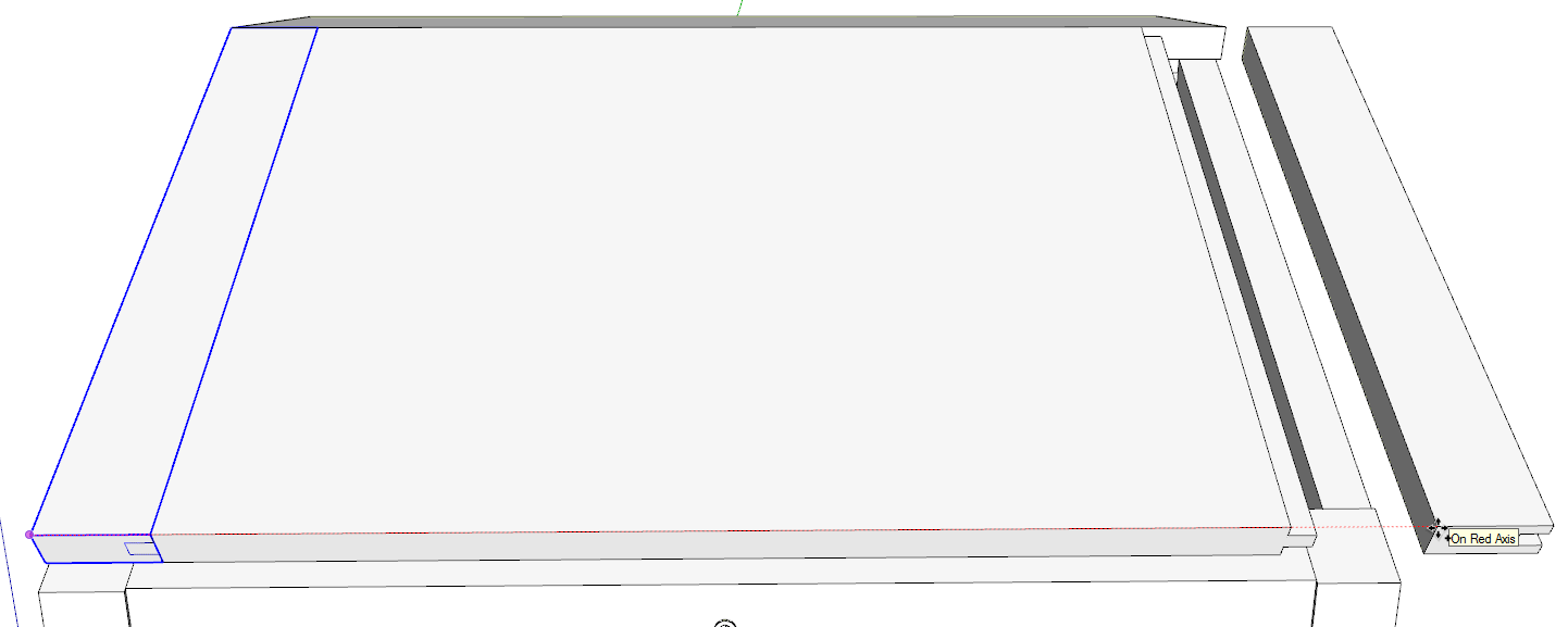
Typically furniture is symmetrical and parts on the left side have mirrored counterparts on the right. The easiest way to create the mirrored counterpart is to copy the orignal component and flip it along the appropriate axis direction. For example, the right side breadboard end is a mirrored copy of the left side component. Here I’ve moved that copy over to the right.
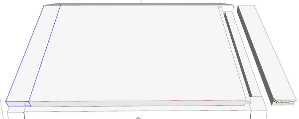
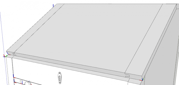
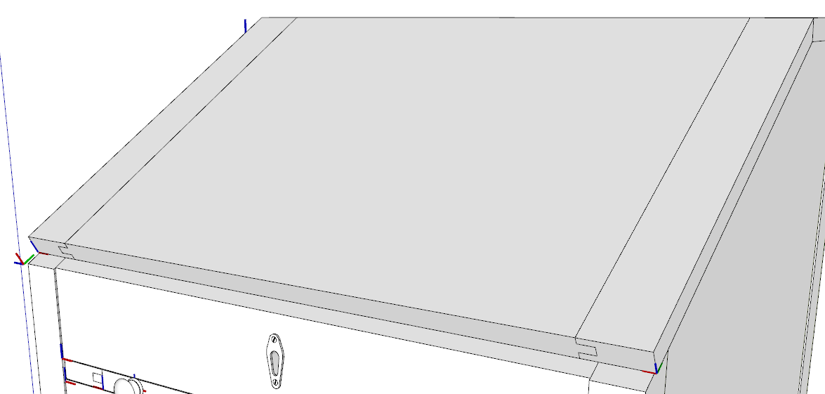
After copying it over to the right, I right clicked on it and chose Flip Along>Component’s Red. The correct flip along direction can be confusing but it really isn’t terribly difficult. Thedirection will be the color of the component axis that is on a line between the copies. In this case it’s the red direction. In this case, it also aligns with the move direction.
Component Origin
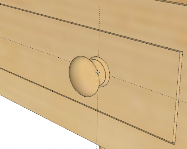
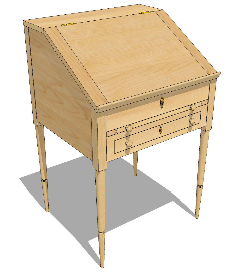
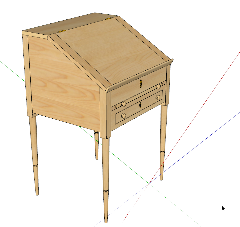
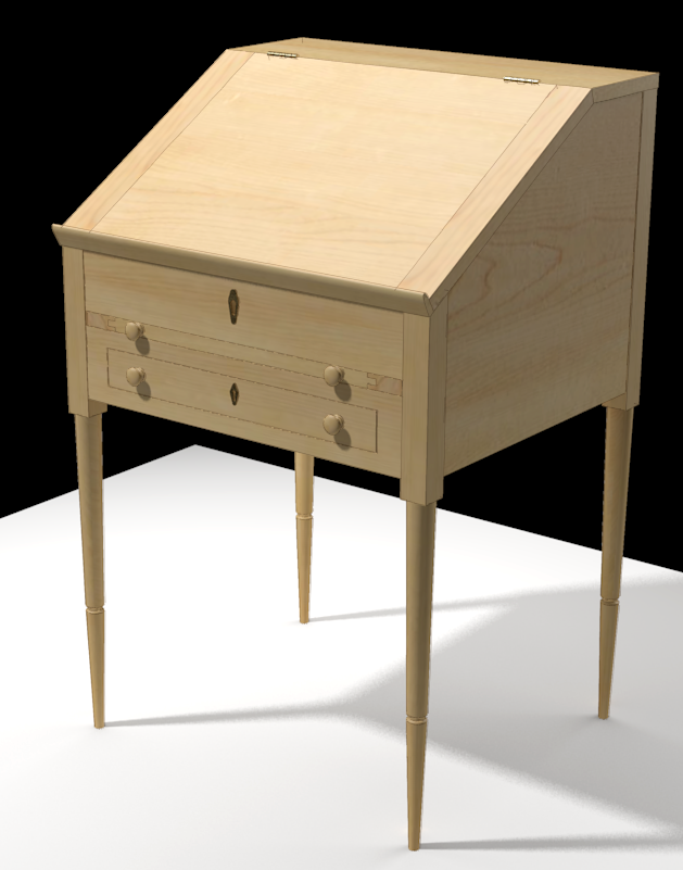
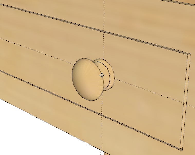
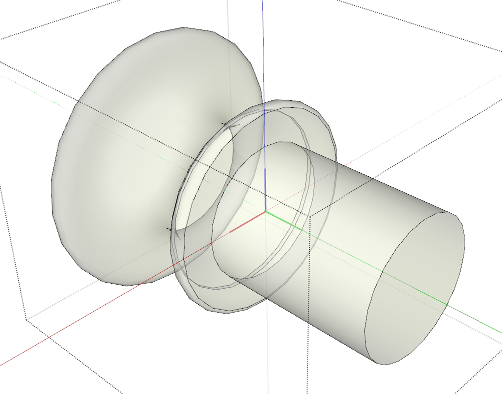
The component origin is the insertion point. It’s the point you’ll hold the component by when you insert it from the Components window. This is very useful for components you’ll use multiple times in a model or in other models. For example the knobs on this desk are ones I made some time ago. I set the origin/insertion point on the centerline of the knob at the shoulder.
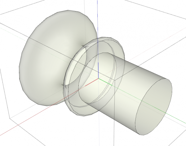
When the knob is brought in from the Components window, it can be dropped right at the intersection of a couple of guidelines for quick and painless location. There’s more about this in some blog posts I did a while back. Here’s a link to one of them.
There are more options for using component axes including setting components up to glue to faces but that’ll be for another post.
–Dave



Comments
As usual, great and thorough explanation of what seems like a simple SketchUp concept. I would add that moving and the flipping more than one component or group gives you the option Flip Along > (Axis) Direction, not Component's (Axis). That can be helpful at times when a component's axes don't align with the model axes, but you move them along one of the model's axes.
I'm looking forward to your discussion on glue to faces. Thanks!
Thank you Carl. I was going to continue the thing on Flipping into another blog post, too. As you mention, flipping more than one component or group at a time ends up flipping along the model axes instead of a component's axes and this can be leveraged. There's more about that flipping thing, too.
-Dave
Silly me! I thought this article was going to be a comparison of different bevels, weights and handle lengths.
I've been wanting to get started using sketchup, this should come in handy. Thanks!
Log in or create an account to post a comment.
Sign up Log in