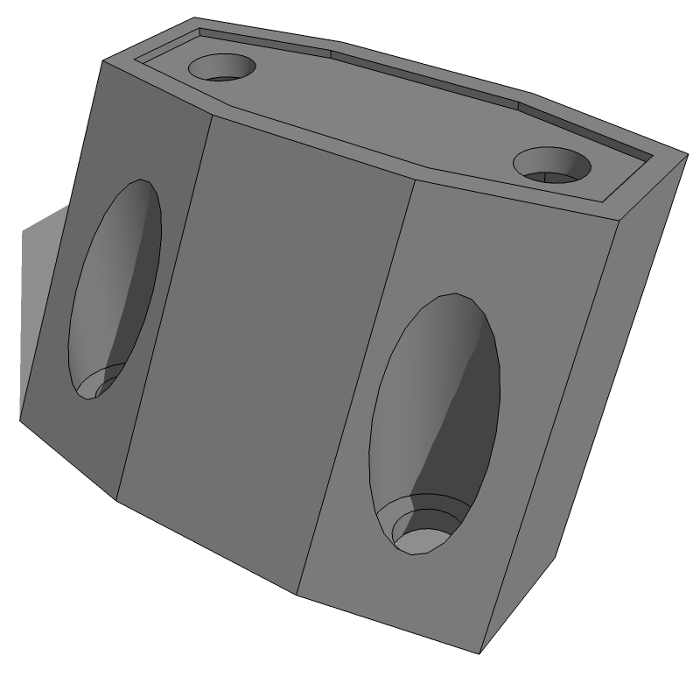
Lately I’ve been working hard on a presentation for the upcoming 3D Basecamp in Steamboat Springs, Colorado. I’ll be presenting some ideas I’ve collected over the years about how to make accurate and efficient models in SketchUp. Of course this presentation is very much in my thoughts at the moment. A beginning SketchUp user contacted me about a project he is working on. It’s a riser or extension block which will be 3D printed from the SketchUp model. He got stuck on creating the holes for the screws. So in thinking about how to get this job done, I was thinking about how to create the model efficiently and accurately.
Since the fellow making this part is a beginner using SketchUp Make, I’ve limited the operations to native tools. There are some extensions that could be used but I think it’s a good idea to get familiar with what the native tools can do first.
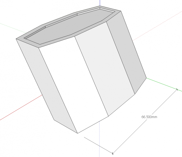
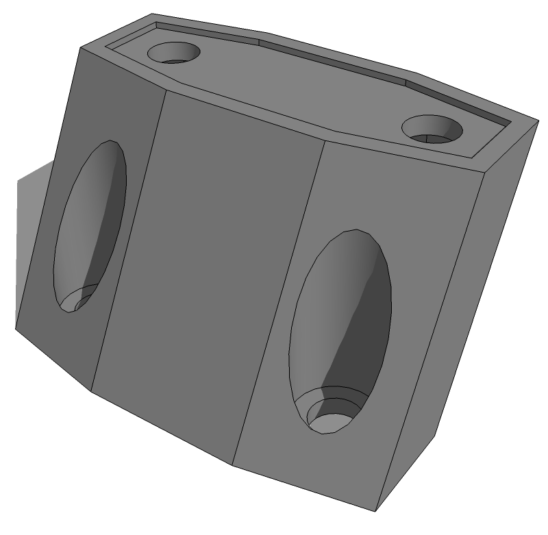
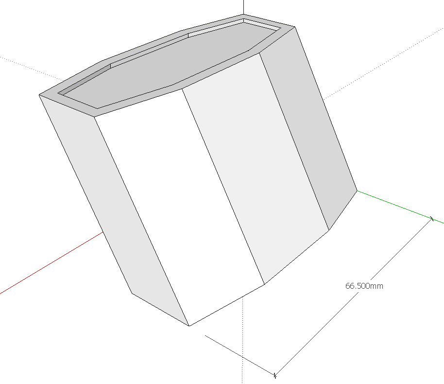
He supplied the model as above ready for the holes. The underside of the top holes need to have hexagonal recesses for hex nuts and the lower holes need to be counterbored for the heads of the cap screws.
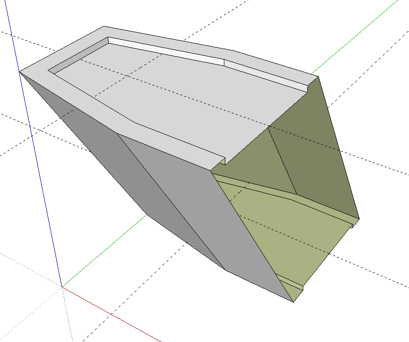
Since the shape is symmetrical, it makes it possible to work on half of the part and make the other half from the first. This is more efficient and reduces the opportunities for errors.
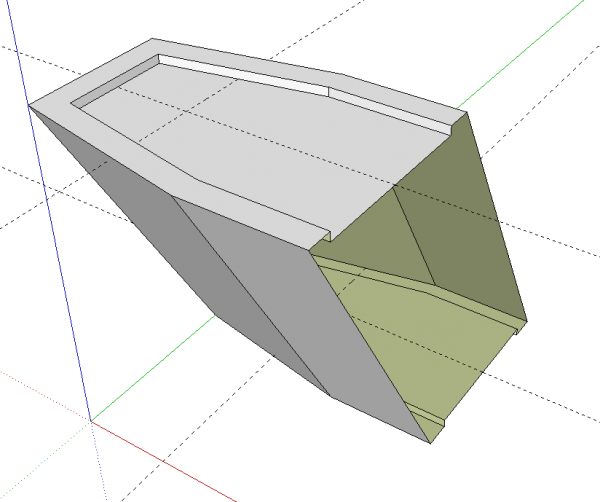
With the block split down the middle, I made it a component and located the center of the holes on the top and bottom faces.
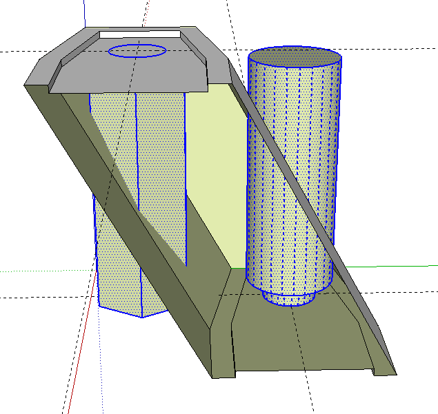
When creating geometry for things such as the holes in this block, I like to work outside the component. This allows me to use the component’s geometry for reference without the worry of damaging the component.
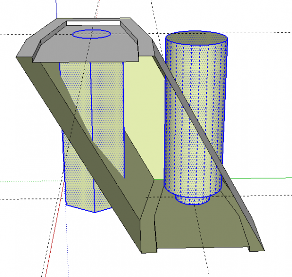
The hole cutting shapes are drawn in situ. I made the hex and counterbore portions extra long to make the clean up easier later. After drawing the shapes for the hole cutters, I reversed the faces. Part of this geometry will become of the holes themselves and reversing the faces now means the face orientation will be correct when we get finished.
With the geometry of the hole cutters selected, hit Edit>Cut (Ctrl-X or Command+X) to place the geometry on the clipboard.
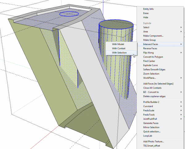
Next, open the component for editing and use Edit>Paste in place to paste the hole cutters into the component geometry.
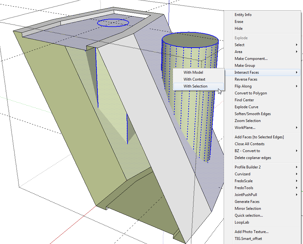
When you paste the geometry into the component, you’ll notice that there are no edges where the hole cutters pass through the angled faces. You’ll need to create those edges with Intersect Faces. I prefer to select only the involved faces and run Intersect Faces>With Selection because this limits the number of faces that need to be looked at for intersections.
It might seem like it would be easier to skip the cut/paste in place step and instead just use Intersect Faces>With Model. The problem with that is while you’d get the intersection edges on the angled face, you wouldn’t have any faces inside the holes. The process I’m showing not only cuts the angled surfaces of the block but it also cuts the hole cutters off at the angled surfaces.
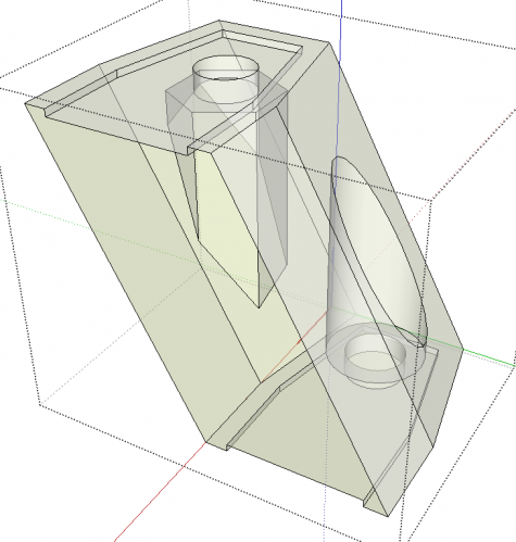
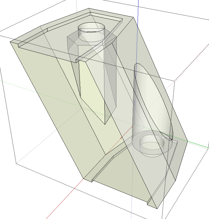
After the intersect routine has run, delete the excess geometry from the hole cutters and the faces skinning over the holes. Switching to X-ray is a good way to see the entire model at a glance so you can look for remaining unneeded edges or faces.
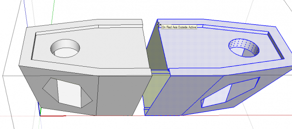
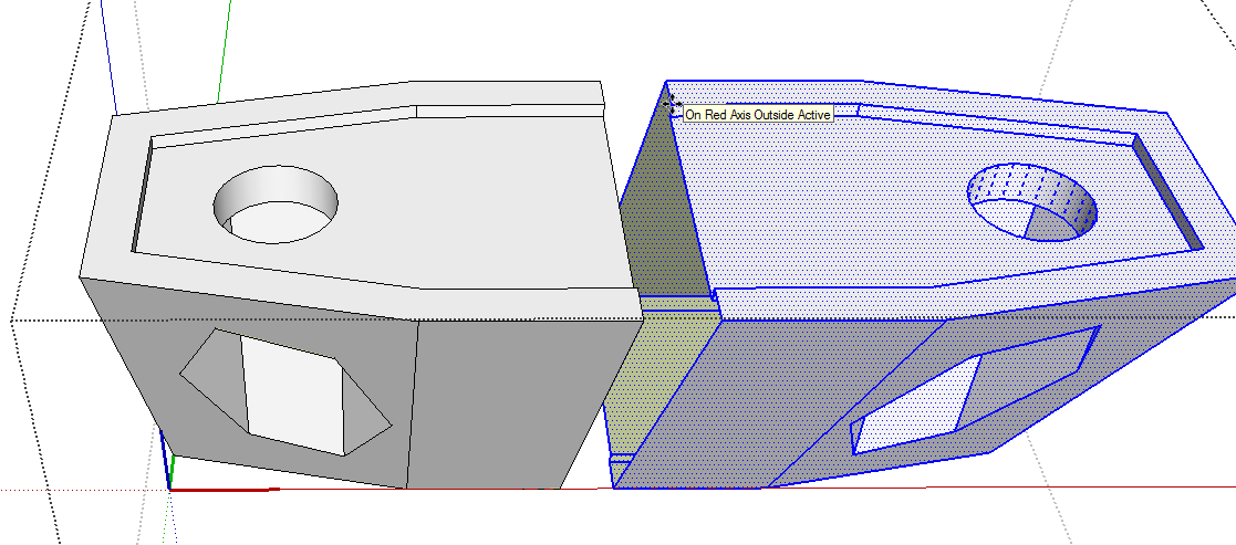
Now all that is left is to make the other half and a little cleanup. Select all of the geometry by triple clicking on it with the Select tool. Triple click will get all of the attached geometry. Then use Move/Copy to make a copy of the selection. Move that copy over in the correct direction. Then right click on the still selected copy and use the Flip Along command to create a mirrored copy of the original geometry. In this case you would use Flip Along>Red Direction. I have keyboard shortcuts set up for the Flip Along commands which makes it very quick and easy to do this.
Then use the Move tool to bring the new half over to the original half. When you grab the copy with the Move tool, grab at a corner that will correspond to a corner at the destination. This will make it easier to accurately place the copy.
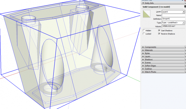
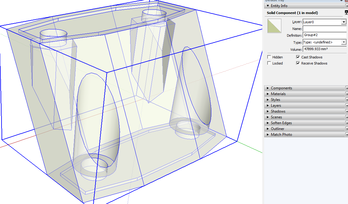
All that’s left is a little cleanup. Erase the seam lines around the part. If you’ve moved the two halves together correctly, the faces should remain. After those seam lines are gone, close the component and the select it. Check in Entity Info to see that it is solid. In order for a component to be acceptable for 3D printing, it must be a solid.
The simple requirements for a group or component to be considered solid in SketchUp are these. The group/component mush not have anything in its wrapper but edges and faces. So nested components will not be considered solid. And every edge must be shared by exactly two faces. If there is a hole, the edges around the hole will only bound one face. If there are internal faces, the edges will be shared by three or more faces and tails extending out from endpoints will bound no faces. A third requirement is that all back faces be on the inside of the shape.
Solids are extremely important for 3D printing but I find it worthwhile to make sure all components are solid in my models even if they aren’t going to be 3D printed because solids are generally much easier to work with as I model. It’s also a sign of clean, accurate and efficient modeling.
–Dave



Log in or create an account to post a comment.
Sign up Log in