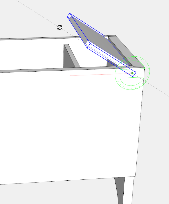
The following are the final steps in modeling the Small Six-board Chest.
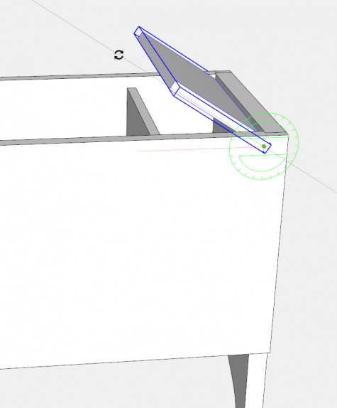
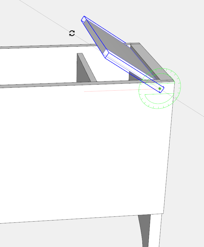
Now that the Till Top is installed with its dowel pivot joints, test the rotation by choosing the Rotate Tool. With the Till Top selected, click the Rotate Tool on the pivot point (where the centerline intersects with the face of the Front). Click to start the rotation, then move the mouse to rotate the Top.
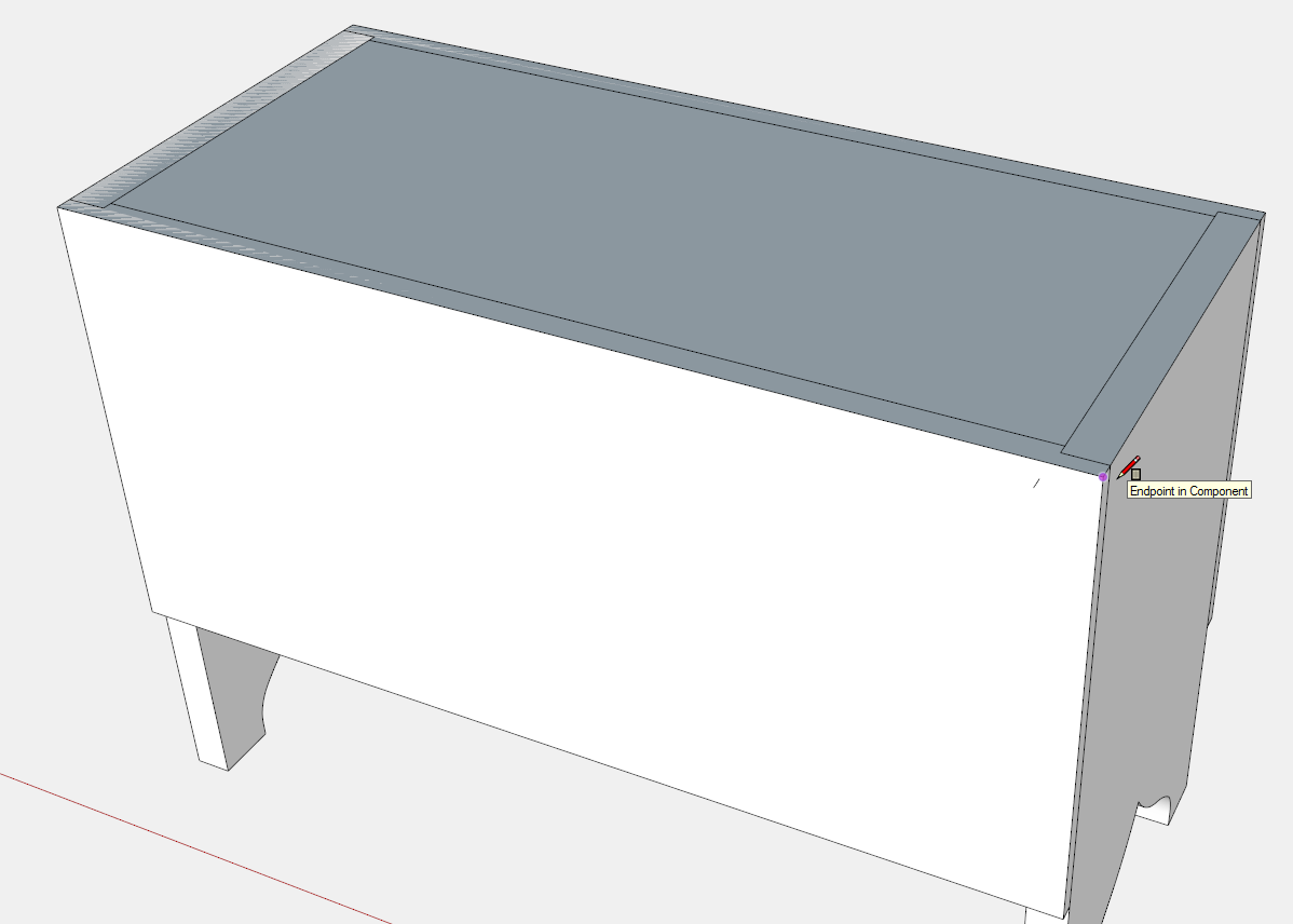
The final component is the hinged Chest Top. Use the Rectangle Tool to create a face across the top of the assembly as shown below.
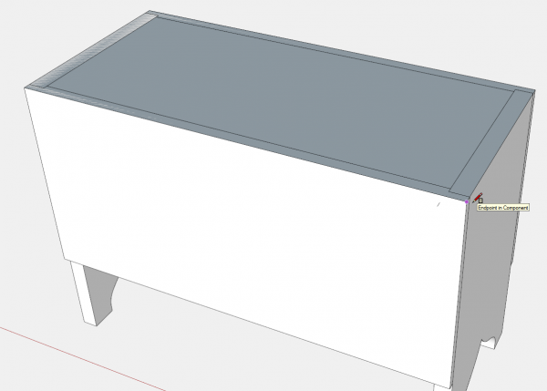
Double click on the face and make the rectangle a component called Top.
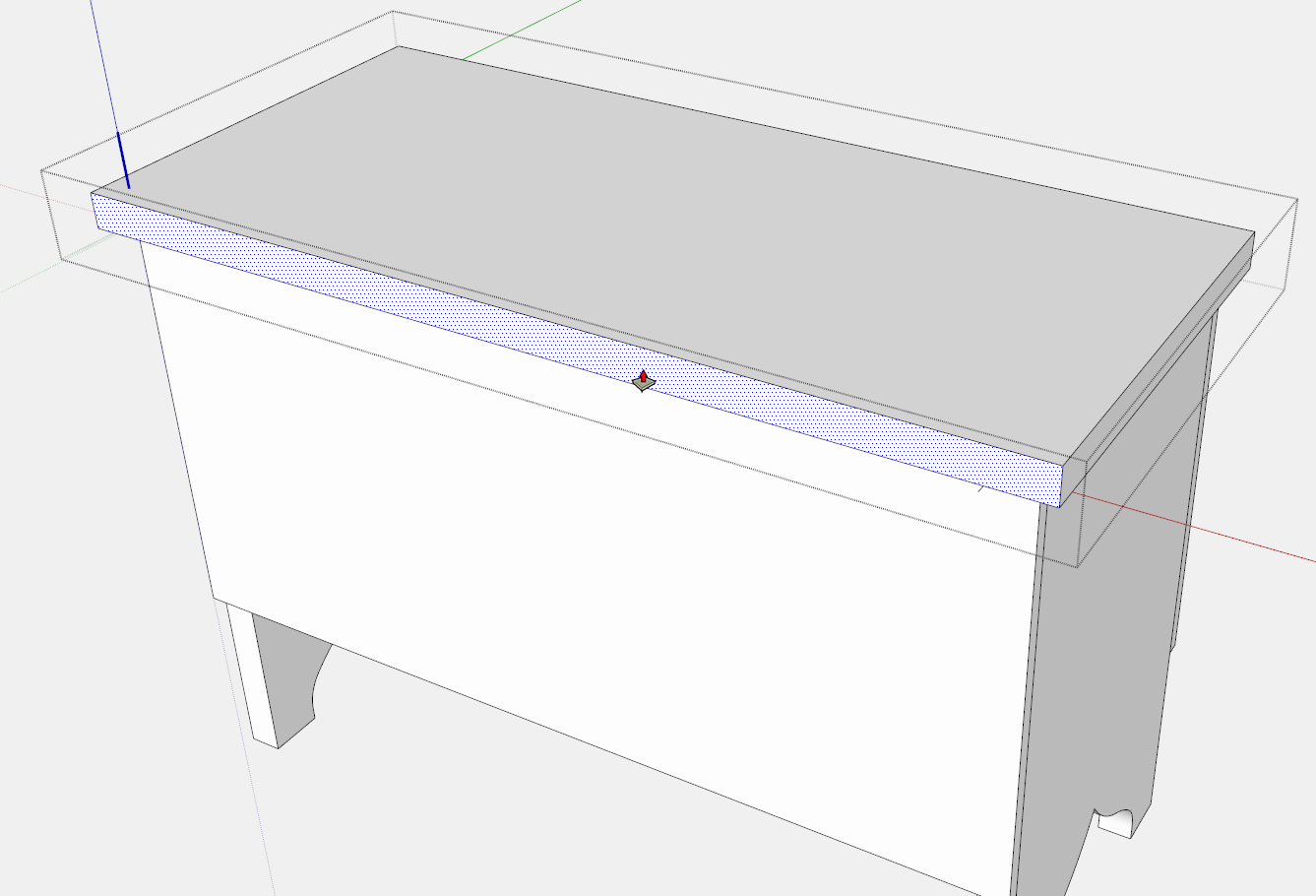
Use the Push/Pull Tool to create the 3/4-in. thickness, and also to extend the ends and front edge, for a 1/2-in. overhang.
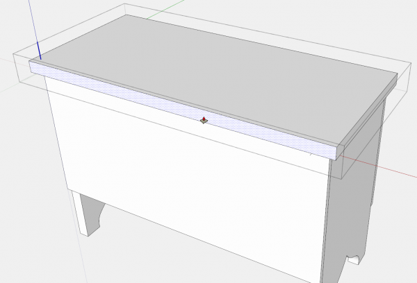
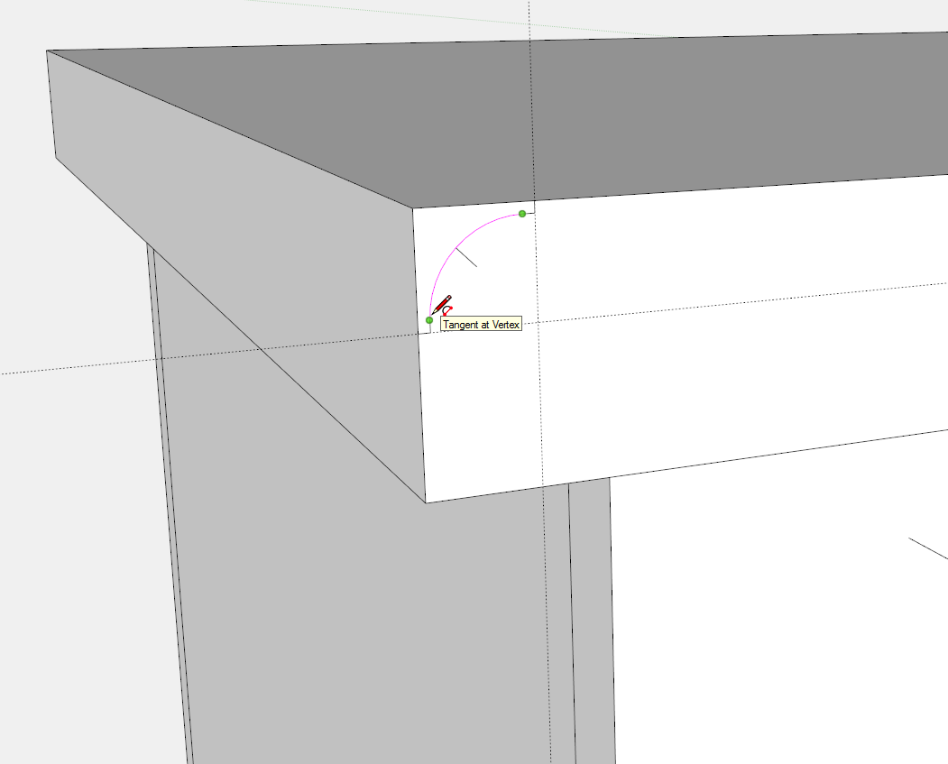
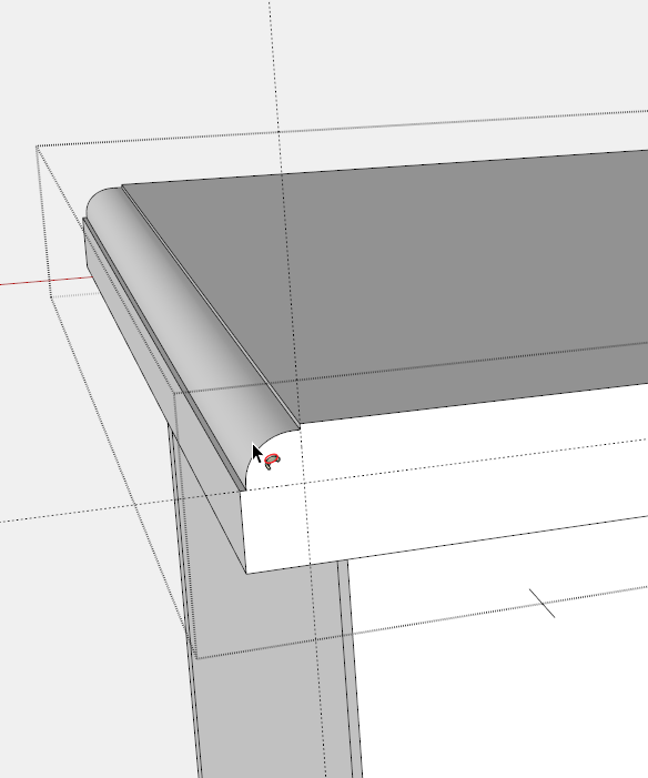
The Chest Top has a thumbnail molded shape along the top edge of the front and both ends. On the upper rear corner of the Top, use the Line and Arc Tools to create the thumbnail profile (on the back edge of the Top) as shown below.
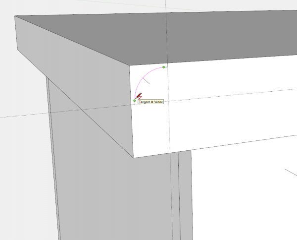
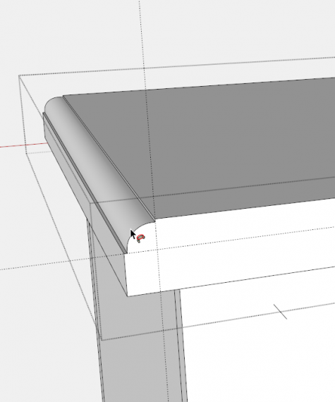
While pressing the Shift key, click the Select Tool, on the three top edges-that is the top front edge, and the two top end edges. Then choose the Follow Me Tool and click it on the profile on the back edge. The Follow Me Tool immediately routes the thumbnail shape on all three of the selected edges.
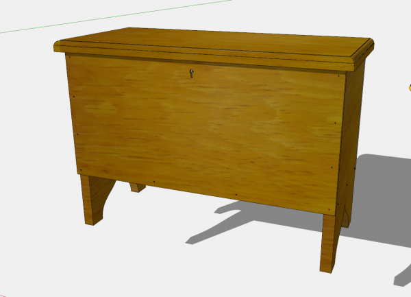
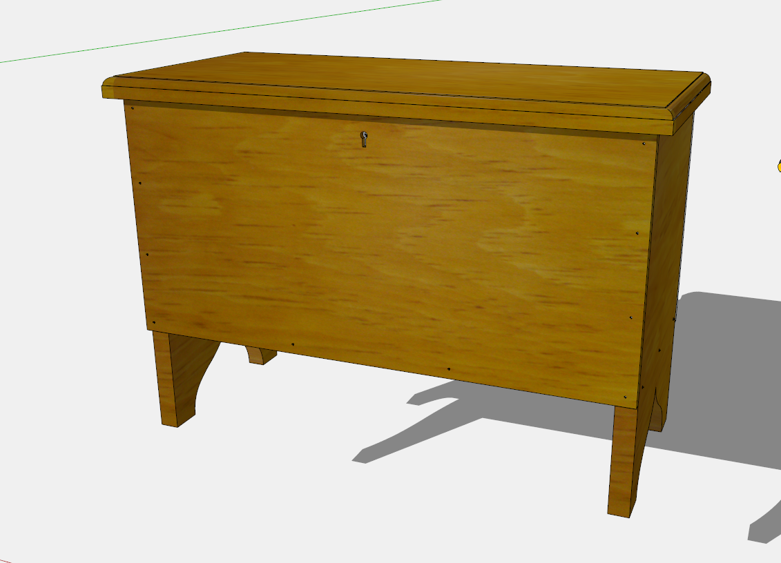
Additional Steps: The figure below shows the final model with all components and joinery, and pine grain. In my own design work, I will do additional work to detail the hardware. This Chest requires butt hinges for the Top, and a chest lock in the Front. I generally include in my models all hardware and associated cut-outs, holes, rabbets, recesses, etc. I find the work on hardware in the model avoids surprises in the shop-such as interferences and size problems. It also gives me exact dimensional information for the hole centers and other cut-outs.
I would also identify locations of fasteners such as, nails and wood screws. The spacing and layout of these details is much easier in SketchUp, and avoids tedious measurements in the shop. Often these spaced fasteners are shown on full-size templates that provide quick mark-up of the components in the shop.
The Drawing Output: After creating the model, the production of drawings is straightforward. I create multiple Scenes for various orthographic, exploded and perspective views of the model, and its individual components. Full size orthographic views (used as templates in the shop) are produced with a few mouse clicks. Hidden line and X-ray styles are available to enhance readability and understanding of complex joinery.
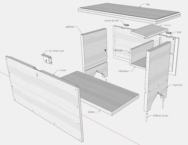
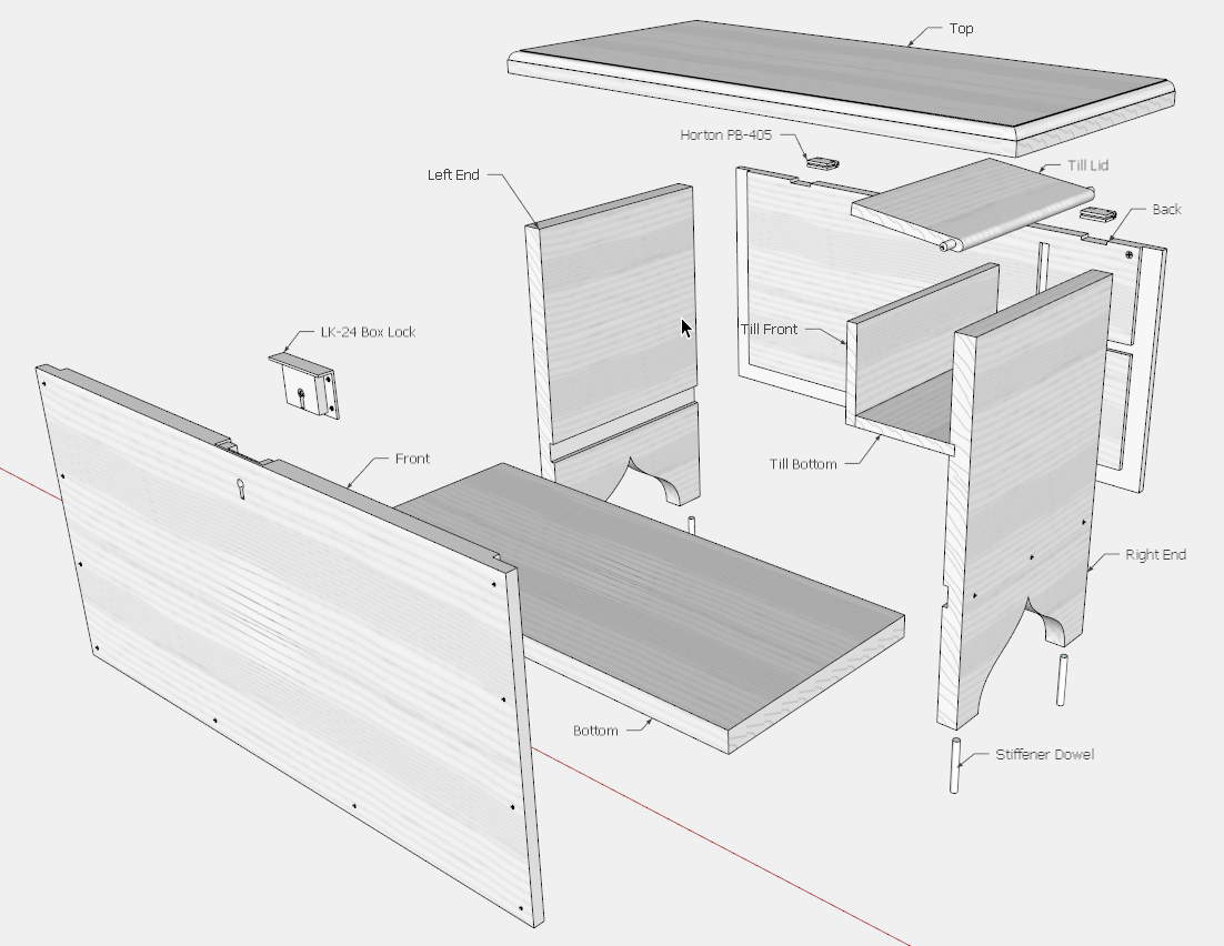
Kettell produced an astonishingly compact one-page drawing. My drawing product is thirteen pages in PDF format, but in justification, includes all dimensions, a page for each component, hinges & key lock, full size templates, location of fasteners, and joint details. Also, an exploded view is valuable as shown below, identifying grain direction of all components.
Tim
@KillenWOOD




Log in or create an account to post a comment.
Sign up Log in