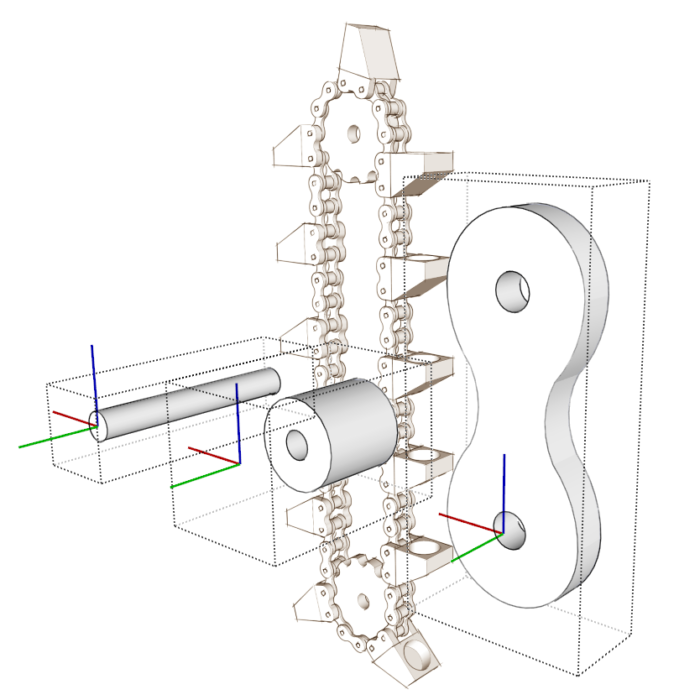
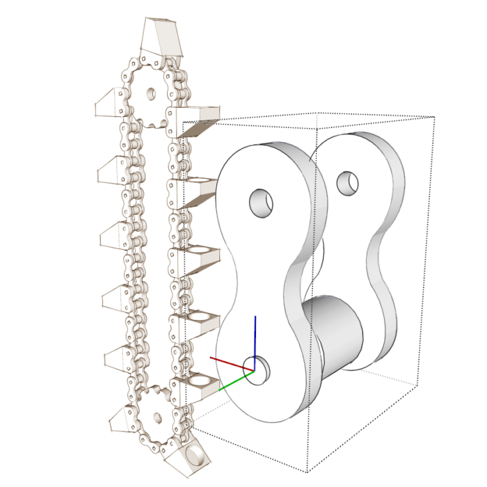
A friend of mine is using SketchUp to make models of the automata and other wooden mechanical devices he builds. Many of his projects include wooden roller chain and sprockets. The other day he asked about modeling those details as well as how to add buckets to the chain to lift marbles. He’s going to be developing plans for his projects so he’s detailing parts like the chain links down to the individual pieces. The video shows how to assemble the links from individual components and then put them together to fit around a pair of sprockets.
Before assembling the links you need to have the parts that make up the links. I used the components he drew of those parts but I made some adjustments to make assembly much easier. When you drag a component in from the Components window, you’ll have hold of it by the component’s origin. Normally when you make a component, the origin is located at the lower front left corner of the component’s bounding box. The axes will be parallel to the model axes. You can manually set origin and orientation of the axes during component creation by clicking on Set Component Axes in the middle of the Create Component dialog box. You’ll see how that works in the video. Alternatively, you can reposition the origin and axes after the fact by right clicking on the component and choosing Change Axes from the Context menu. Keep in mind these options are only available for components, not groups.
As you can see in the image below, I set the origin for the pin at the center of one end. For the roller and the link plate, I put them on the pin in their proper locations and then set their origins at the center of the end of the pin. You’ll see that in the video, I can drop each of the components where it needs to be when dragging it in from the Components window.

As you’ll see in the video, after assembling the first link, I made a nested component of the parts and I set that component’s origin at the center of the pin as well. This makes a number of the later steps easier.

The practice of placing the origin and component axes as I did not only makes it simple to bring in a component and place it where I want it needs to go, it also makes it possible to swap one component with another. When replacing a component in your model with a different one, the new component will be positioned with its origin in the same location as the previous one and the axes will be aligned to match those in its predecessor. I’ve written in the past about how I place the axes for components such as pulls, knobs, and hardware. Here’s a link to one of those posts. In the video you’ll see several examples of editing a component to make a new one while leaving the origin in the same location relative to the original component. If you give some thought to how you are editing the component, you can save yourself a lot of work as you go.
By the way, if you want to see some of my friend’s work, check out his You Tube channel here.
–Dave


Comments
Fantastic video , I learn so many sketch up tips when I read and watch your posts. Thanks Dave
Me too; learned several new things from this video.
The title does not do the content justice. So much to draw from as in work flow, technique`s and hidden gems. The replace selected option in the components dialog box is real cool.
Log in or create an account to post a comment.
Sign up Log in